HCS08 VGA Output

This reference design is a simple VGA signal generation that uses the Freescale’s MC9S08SH16VTJR, which is an 8-bit microcontroller that has Central Processor Unit (CPU) speed of 40MHz with a maximum bus frequency of 20MHz. It has an internal clock source module containing a Frequency-Locked Loop (FLL) controlled by internal or external reference. Its precision trimming of internal reference allows 0.2% resolution and 2% deviation over temperature and voltage with 1.5% deviation using internal temperature compensation. The simplest instructions such as NOP take 1 bus cycle, the other instructions take more cycles, and for example RTS takes 6 bus cycles.

The VGA signal has 5 components that include horizontal synchronization, vertical synchronization and three analog color signals. The analog color signal range is 0-0.7V with 75Ω impedance and sync signals are TTL signals. The device has a refresh rate of 60Hz with 640 x 480 resolutions, and the pixel clock is 25.175MHz. The display refresh rate is therefore slightly lower, somewhere around 57Hz. The implementation for video signal generation is in the form of an infinite loop where one loop cycle is equal to one video frame. During every frame the video signal is generated line by line. A subroutine was created that draws multiple lines, where the number of lines is expected in the A register. Every line is divided into 16 parts. Colors of these parts are stored in RAM. Pointer to this array is expected in the HX register. Each of the 3 color channels is 1 bit only having 8 available basic colors.

The device is very simple that adds character to an ordinary static image displayed in an old CRT display. This can be easily reprogrammed as desired by the user. A scrolling strip may be added that is implemented as a rotating buffer. The circuit can be easily constructed using only an MCU, crystal oscillator, VGA connector and few capacitors.

HCS08 VGA Output – [Link]

Sinewave Generator

Picture

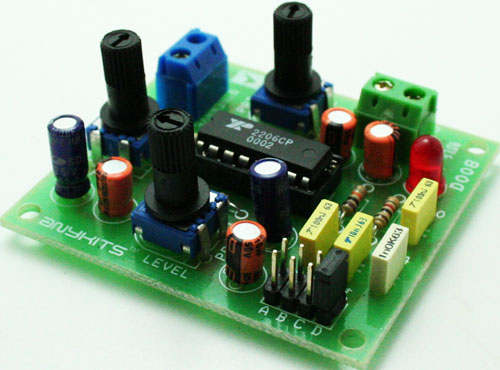
Sine wave Generator project will provide you with a Sinusoidal Waveform output to test various instruments.  You can also use the High quality output from this kit to insert a tone modulation in your audio and RF equipment.  This kit is designed using XR2206 IC to provide High Stability and Accuracy.

  • Supply input 12 VDC Max @ 50 mA
  •  Range: Jumper selectable and preset tunable range of 10 Hz – 100 KHz
  •  Output Level can be controller with onboard preset
  •  Power-On LED indicator
  •  Screw terminal connector for easy connection
  •  PCB dimensions 55 mm x 50 mm

Sinewave Generator – [Link]

Sinewave generator

Picture

Sine wave Generator project will provide you with a Sinusoidal Waveform output to test various instruments.  You can also use the High quality output from this kit to insert a tone modulation in your audio and RF equipment.  This kit is designed using XR2206 IC to provide High Stability and Accuracy.

  • Supply input 12 VDC Max @ 50 mA
  •  Range: Jumper selectable and preset tunable range of 10 Hz – 100 KHz
  •  Output Level can be controller with onboard preset
  •  Power-On LED indicator
  •  Screw terminal connector for easy connection
  •  PCB dimensions 55 mm x 50 mm

Schematic

Schematic


Parts List

BOM

ZofzPCB: FREE 3D Gerber Viewer

Rafal @ zofzpcb.com writes:

Many CAD designers, including myself, are equipped with powerful graphic cards. I definitely wanted to use a gamer graphic and I wanted to fly. There is the result, 3D Gerber viewer with newly implemented display of components. Components are guessed, not yet from BOM. Download at http://www.zofzpcb.com Do not forger to check the Autopilot.

ZofzPCB: FREE 3D Gerber Viewer – [Link]

4 Channel Triac Board

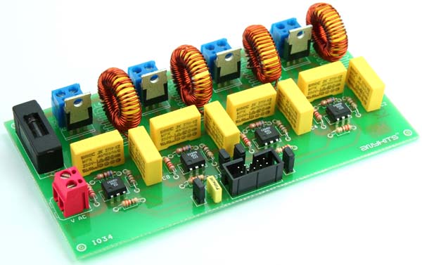
4-CHANNEL-TRAIC-BOARD-PIC01

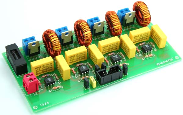
Opto-Isolated 4-Channel Triac Board (R) is used for fast switching applications. Ideal for switching mains circuits, lights, appliances and small load. Each circuit is effectively isolated with opto-isolators on each channel, TTL inputs control each channel.

  • Trigger input 2-12 VDC
  • Mains supply input 230 VAC or 110 VAC
  • Output 1 A @ 230 VAC (RMS ON STATE CURREN 4 AMPS EACH CHANNEL)
  • Snubber circuit for inductive load
  • Jumper for common cathode ground
  • Box Header connector for connection of control signal
  • Screw terminal connector for Load
  • Four mounting holes of 3.2 mm each
  • PCB dimensions 139 mm x 73 mm

4 Channel Triac Board – [Link]

4 Channel Triac Board

4 CHANNEL TRAIC BOARD PIC01

Opto-Isolated 4-Channel Triac Board (R) is used for fast switching applications.  Ideal for switching mains circuits, lights, appliances and small load.  Each circuit is effectively isolated with opto-isolators on each channel, TTL inputs control each channel.

  • Trigger input 2-12 VDC
  • Mains supply input 230 VAC or 110 VAC
  • Output 1 A @ 230 VAC (RMS ON STATE CURREN 4 AMPS EACH CHANNEL)
  • Snubber circuit for inductive load
  • Jumper for common cathode   ground
  • Box Header connector for connection of control signal
  • Screw terminal connector for Load
  • Four mounting holes of 3.2 mm each
  • PCB dimensions 139 mm x 73 mm

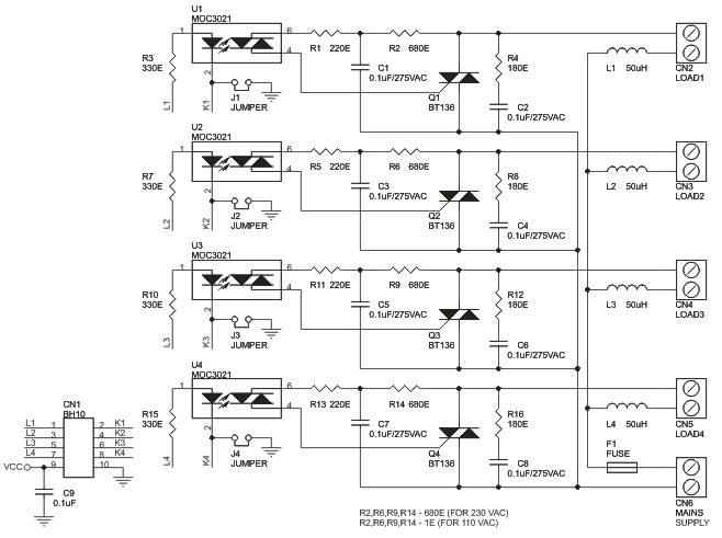
Schematic

4 CHANNEL TRAIC BOARD SCHEMETIC


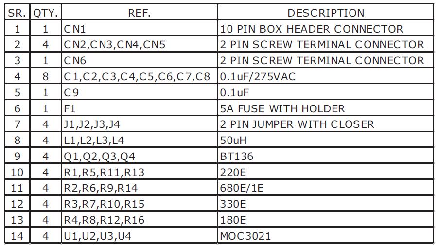
Parts List

4 CHANNEL TRAIC BOARD BOM

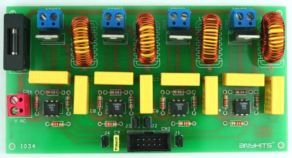
Photos

4 CHANNEL TRAIC BOARD PIC 02


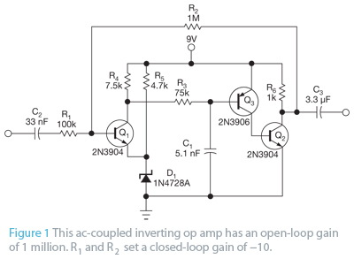
Build an op amp with three discrete transistors

294772-build_an_op_amp_with_three_discrete_transistors_figure_1

by Lyle Russell Williams:

You can use three discrete transistors to build an operational amplifier with an open-loop gain greater than 1 million (Figure 1). You bias the output at approximately one-half the supply voltage using the combined voltage drops across zener diode D1, the emitter-base voltage of input transistor Q1, and the 1V drop across 1-MΩ feedback resistor R2.

Build an op amp with three discrete transistors – [Link]

High Reliability, High Isolation Single-Pole-Double-Throw RF switch

In telecommunications, ideal RF switches require low insertion loss, high isolation and linearity. The IDT F2912 is a single-pole-double throw RF switch capable of having low insertion of loss of 0.4dB at 1GHz and a RF1 to RF2 Isolation of 74dB at 1GHz with extended temperature of -55C to +125C making it highly reliable. In addition, this covers a broad frequency range from 300kHz to 8000MHz.

As a switch, it’s capable of 3 types of controls namely switch control, mode control, and logic control. The switch control includes (3 states and 2-pin control input) or (2 states and 1-pin control input). The 3 states and 2-pin control input operates like a XOR logic gate, if there is a high value input from the control pin either CTL1/CTL2 will trigger RF1 to RF Com if CTL1 is High or RF2 to RF Com if CTL2 is High. While the 2 states and 1-pin control input, a high value CTL2 will trigger RF2 to RF com and a low value CTL2 triggers RF1 to RF Com leaving the CTL1 a “don’t care”. The mode control use either (2-pi

n control: CTL1 and CTL2) or (1-pin control: CTL2). When RF1 and RF2 ports are both open (State 1), all 3 RF ports are terminated to an internal 50Ω termination resistor. When RF1 or RF2 port is open (State 2 or State 3 OFF condition), the open port is connected to an internal 50Ω termination resistor. When RF1 or RF2 port is closed (State 2 or State 3 ON condition), the closed port is connected to the RF Com port. The logic control operates using logic voltage 1.8V and 3.3V to operate logic CTL (pin18) VCC and GND respectively.

This circuit design can be applied more on base station 2G, 3G, 4G, portable wireless, repeaters and E911 systems, digital pre-distortion point to point infrastructure, public safety infrastructure WIMAX receivers and transmitters, military systems, JTRS radios, RFID handheld and portable readers, cable Infrastructure, wireless LAN, test/ ATE Equipment.

High Reliability, High Isolation Single-Pole-Double-Throw RF switch – [Link]

TOP PCB Companies