MCP2221 HID Library

mcp2221breakout

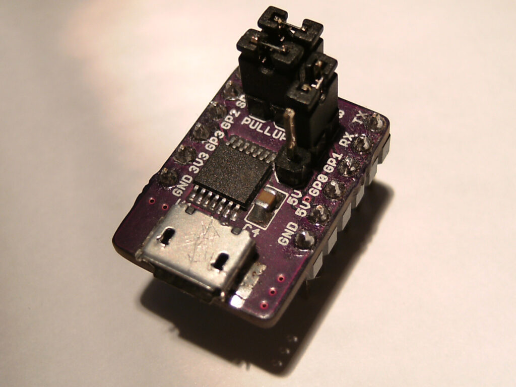
Zak’s Electronics Blog published a new library and breakout board for MCP2221 USB to UART interface IC:

This is a library for interfacing with the HID features of the MCP2221 USB to UART and I2C/SMBus serial converter from Microchip. The converter includes 4 GPIO pins, 3x 10-bit ADCs, 1x 5-bit DAC and more. Microchip does provide a library for interfacing with the chip, however it is supplied as proprietary DLLs. This project aims to be an open-source and multi-platform alternative. libraryThis library also makes use of HIDAPI.

MCP2221 HID Library – [Link]

ESP8266 + Attiny85 + DHT22 Temperature/Humidity Logger

photo1

by guibom @ github.com:

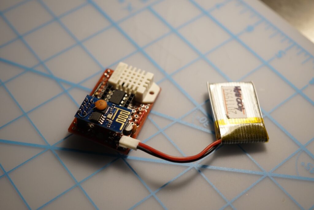
Basic ESP8266 + Attiny85 + DHT22 Temperature and Humidity logger. I’ve made this to experiment a bit with the ESP8266 wifi module, and hopefully make a remote sensor that posts the data to my server.

I wrote the code to work with both an atmega328 and a attiny85. The mcu sleeps in between readings, consuming about 35uA while powered down (the ESP module, even when chip-disabled, is responsable for about 80% of that).

The UDP messages are very specific to my use case; I have a node-red UDP listener that receives JSON strings from the logger and forward them as MQTT messages. But it should be very easy to change it to send whatever you might need.

ESP8266 + Attiny85 + DHT22 Temperature/Humidity Logger – [Link]

Enclosure 1455 NHD won’t be scared by a hot summer

obr1744_1

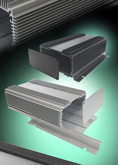
The latest extruded aluminium enclosure from Hammond production – 1455 NHD is suitable even for devices requiring more intensive cooling.

The latest addition to the family of the popular 1455 enclosure series is the enclosure with “NHD” suffix – where “HD” marks “Heat Dissipating” design. Six fins (zones) with cooling ribs significantly improve cooling. With its “N” size it´s suitable for PCB of the “Eurocard” size (100x160mm).

Possibilities of the new enclosure
They´re really wide. Thanks to seven inner slots, it´s easy to find a suitable position for your PCB. Removable front panels consequently secure a PCB against movement and at the same time they can be easily machined by drilling/ milling for usage of various connectors, switches, LEDs,…

And it´s still not all …
As the body of the enclosure consists of two pieces – with a removable base plate, it provides excellent reach to inner electronics even in case, when we don´t want to remove the PCB from the enclosure. The enclosure also contains six internal and two external T slots enabling installation of various components inside (by fixings sliding into the slot) or enables fixing of the enclosure to a panel/wall or similar.
Upon request we´re able to provide you any of the two versions – 1455NHD1601 (natural elox) as well as 1455NHD1601BK (black).

Enclosure 1455 NHD won’t be scared by a hot summer – [Link]

Triacs – How to calculate power and predict Tjmax

apps3

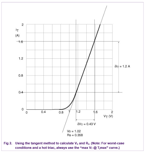
An application note from NXP on how to calculate the power dissipated by the triac:

This Application Note describes how to calculate the power dissipation for triacs and Silicon Controlled Rectifiers. Thermal calculations are also included to help the circuit designer to predict the maximum junction temperature or calculate the required heatsink thermal resistance. Four worked examples ensure that all the power and thermal questions that arise during the design process are covered.

Triacs – How to calculate power and predict Tjmax – [Link]

Milk in Fridge – Internet of Things

F5AM7R9ICN7GGRS.MEDIUM

by samsungite @ instructables.com:

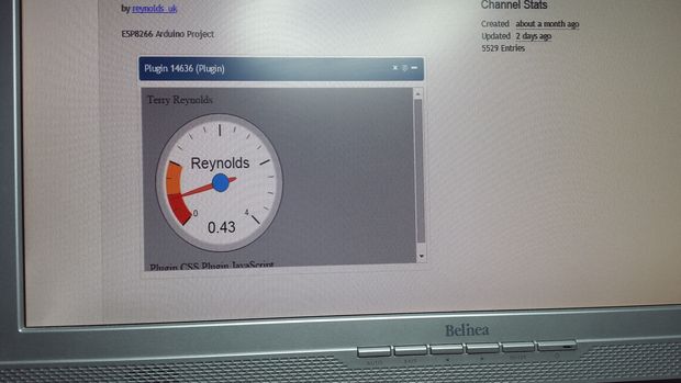
I think that one day, all food cupboards & fridges/freezers will be smart. All products will have an RFID or video recognizable label which will update a list of product usage. Your local supermarket will gather this information & replenish your products as required – who knows ??

Milk in Fridge – Internet of Things – [Link]

50,000V High Voltage Power Supply

FCO96BGIDUR7T94.MEDIUM

by Victor8o5 @ instructables.com:

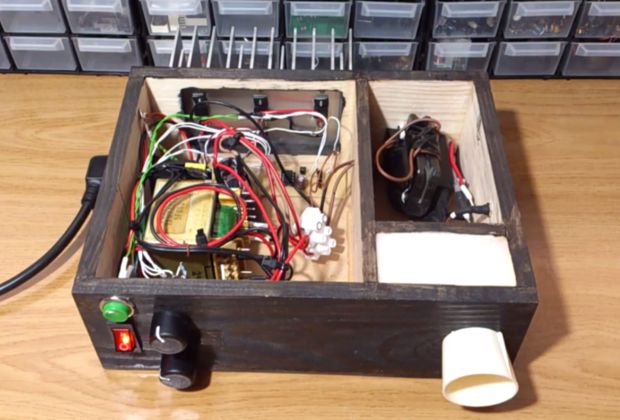
This high voltage power supply has been designed to output a fixed voltage of around 50kV, it could easily be converted to an adjustable supply by connecting a variac in case of using transformers or by adding some extra circuitry to regulate the power going in. I initially thought about a high frequency PWM to regulate the power going into the capacitors, but I abandoned the idea. I found that adjusting the frequency is enough to make the voltage vary by a significant amount, allowing some control over it, this happens because the flyback must operate at a certain frequency in order to maximize the output.

50,000V High Voltage Power Supply – [Link]

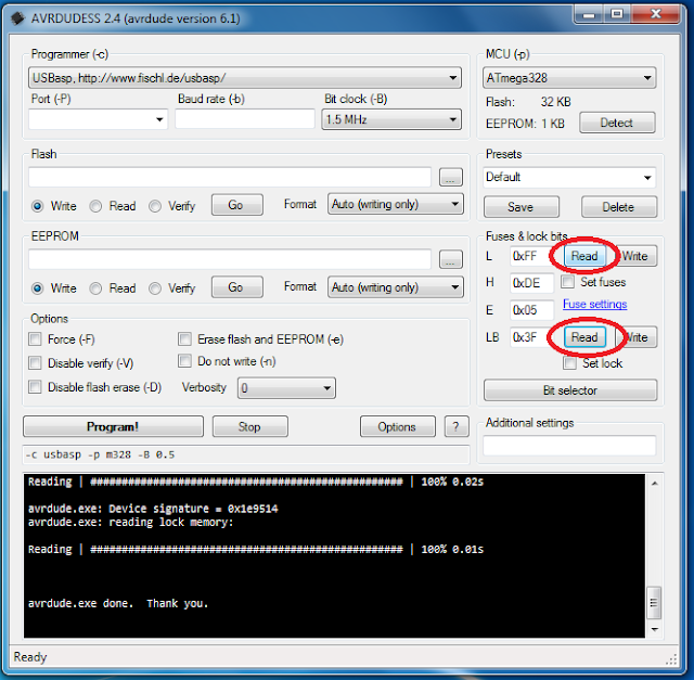
Burning Arduino Bootloader on ATMega328 using USBasp Programmer

In this tutorial, you’ll learn how to burn Arduino bootloader on a new ATmega328 using USBasp ISP programmer. Every Arduino Uno Board comes with a microcontroller called the Atemga328P, and they are already pre-program with Arduino Bootloader firmware. Therefore, there is no need to burn Arduino bootloader into those Atmega328P chips again. Here, we will be focusing on burning the Arduino bootloader on an off the shelf Atmega328 chip so that you could make your own DIY Arduino board or deploy your Arduino-based circuit to a printed circuit board.

NOTE – The bootloader is the little program that runs when you turn the Arduino on or press the reset button. It’s main function is to wait for the Arduino IDE on your computer to send a new program, which then is written to Arduino memory.

Required components:

First of all wire up the circuit in the breadboard as shown in the diagram above. Please connect all the connections carefully.
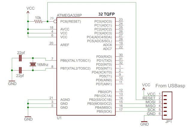
In above circuit JP1 is where USBasp programmer is connected. Connect all the wires carefully as per above diagram using a jumper wire.

Software Install

If you wire up your circuit correctly then it’s time to load hex file which is located in your Arduino software folder. Here is the complete path for Arduino 1.x in windows – C:\Program Files (x86)\Arduino\hardware\arduino\avr\bootloaders\optiboot\optiboot_atmega328.hex you can also download from here optiboot_atmega328

Next, you need to install AVRdude software and USBasp Programmer Driver.

Bootloading

Open the AVRdude software and select programmer type from the drop-down list shown in below image. In our case programmer is the USBasp programmer.
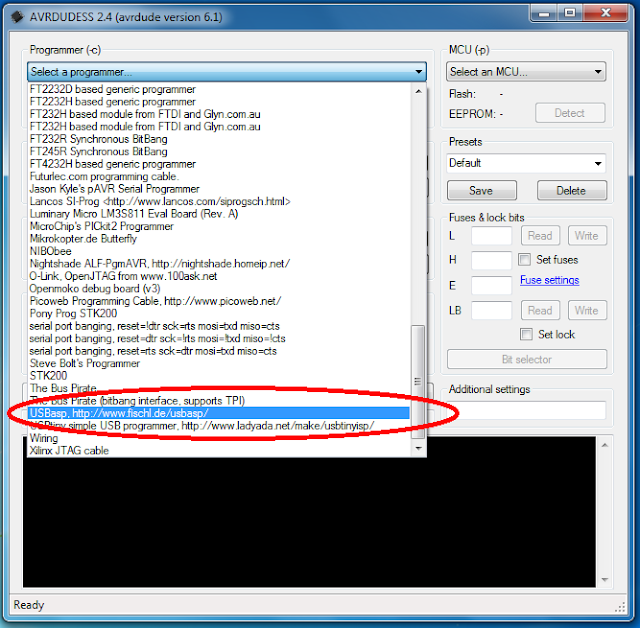

After Selecting programmer type click on “Detect” so programmer automatically detects ATmega328. If you have any problem with detecting microcontroller check all connections carefully.
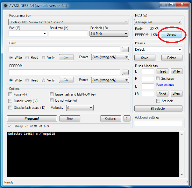
After detecting microcontroller, it’s time to read fuse bits and lock bits. As shown in below screenshot click on “Read.”

Make sure you don’t write wrong fuse bits, otherwise your microcontroller will stop working.

The default value of fuse bit.

  • LOW Fuse : 0x62
  • HIGH Fuse : 0xD9
  • Extended : 0x07
  • LOCK :0xFF

To configure the Atmega328 for use with Arduino Uno boards, set the fuse settings as below:

  • LOW Fuse=0xFF
  • HIGH Fuse=0xDE
  • Extended Fuses=0x05

Under Flash, browse the hex file optiboot_atmega328.hex which you downloaded previously, select the file and click “Open.”
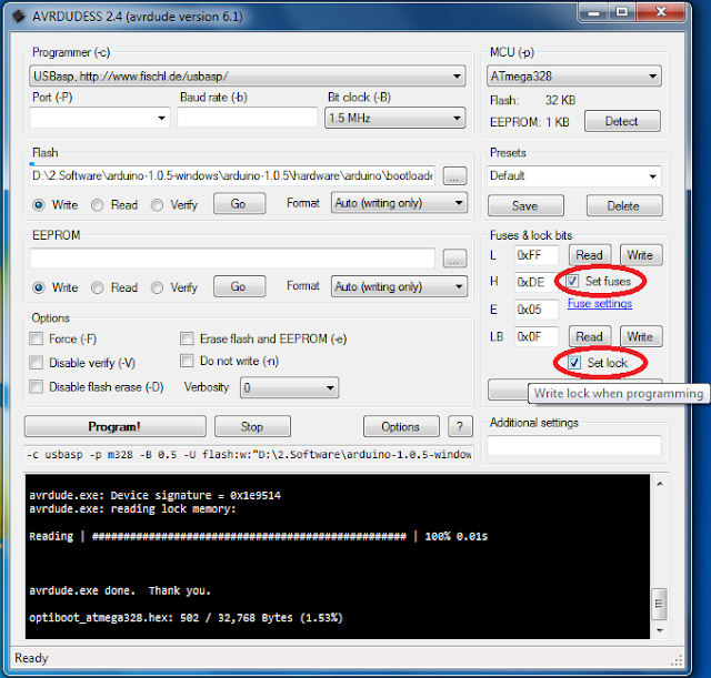
Now click on “Program!” button. It will take about 30 seconds. You can now use your cheap ATMega328 microcontroller as a regular Arduino.
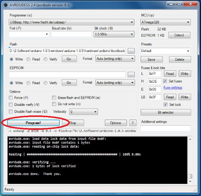

You now have an Atmega328P that can be programmed with the Arduino IDE. Just plug in your new Atmega328P into any Arduino Uno board or using a USB to Serial Converter to upload your Arduino Sketch.

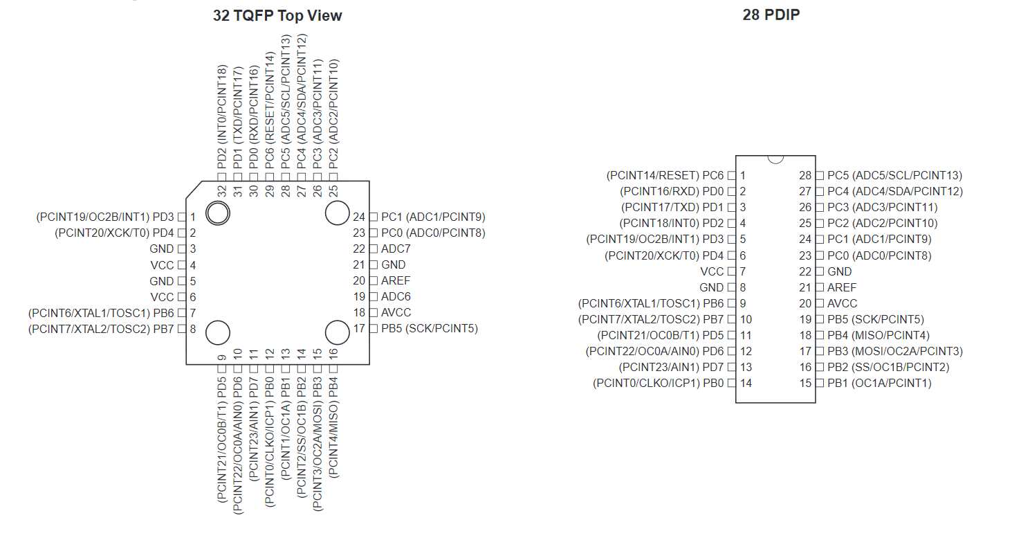
ATMega328 Pinout (TQFP and PDIP)

The schematic at the start of the post is for the 32 TQFP package and you can easily modify it for the 28 PDIP version using the following pinout.
 

The tutorial’s part list is sponsored by www.lcsc.com, the wholesale retail electronic components store in China. To learn more about LCSC.com read their company profile:

  • Who we are: LCSC Electronics is one of the fastest growing suppliers of electronic components in China. LCSC Electronics has been committed to offering multitudinous, genuine and in-stock items, since its founding in 2011.
  • Main Products: Our extensive product includes semiconductors, resistors, capacitors, diodes, inductors, connectors, transistors, and sensor.
  • Line cards: LCSC purchasing teamwork persistently to select the Chinese trusted manufacturers according to a high standard. We have 72 authorized brands suppliers which are still increasing by time, 173 international brands and 489 Asian brands suppliers.
  • Warehouse: LCSC Electronics has a self-owned modern component warehouse with 10,000 ㎡ by stocking more than 180,000 kinds of parts. LCSC’s project of building the Technology Industry Park with an area of 350,000 ㎡ was launched in Jiangsu in July 2018, which provides a solid foundation for the development of stocking and supply chain in the next 5-10 years and it is Asian largest in-store components warehouse.
  • Shipping: In-stock orders are ready to be shipped in 4 hours and send out to each corner of the world by DHL, FedEx EMS, USPS, and other carriers.

Analog to Digital Converter module

A2 D PIC 2

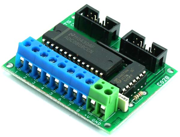
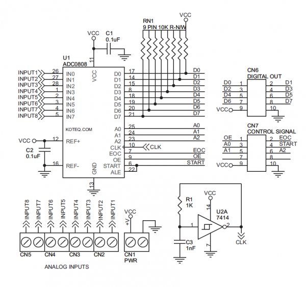
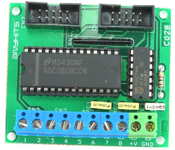
This simple A2D (Analog to Digital) Converter Board can log upto 8 channel of analog signal with 8 bit resolution.  This board uses the  ADC0808 chip from National Semiconductor.

  • Two standard box type header connector for easy connection of the board to various development boards or project
  • Separate box header for Data and Control signal for the ADC
  • Screw terminal connector for easy connection of Analog signal input or sensor connection to the board
  • +5 VDC and Gnd connection available for sourcing supply for your sensor or add-on interface or signal conditioner board
  • Onboard oscillator source for the analog to digital converter
  • Four mounting holes 3.2 mm each
  • PCB dimensions 54 mm x 63 mm

Schematic

schematic

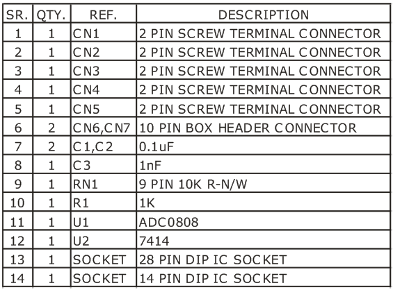
Parts List

BOM

Photos

A TO D PIC1

Audio Oscillator with Frequency Counter

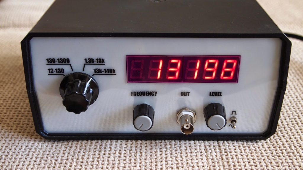
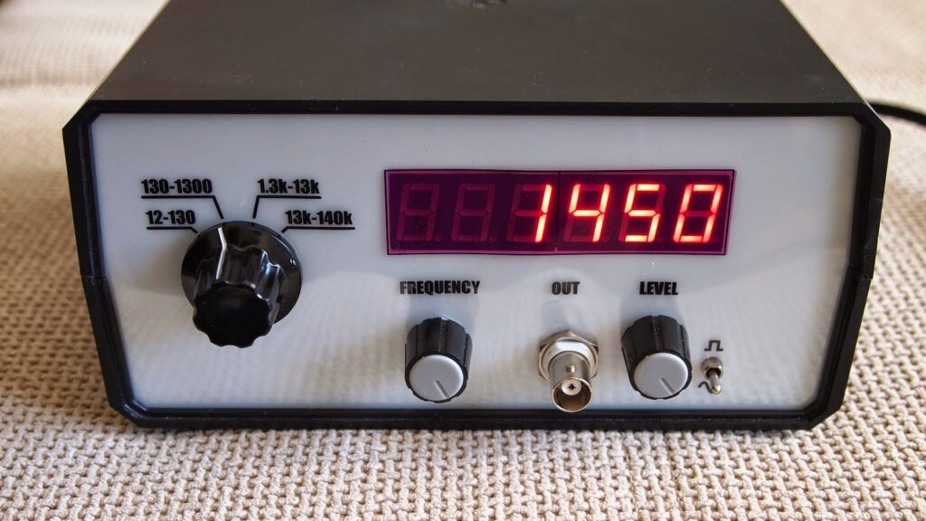
This project is not completely new. In fact, the oscillator is made from the same schematic as in one of my previous projects and only the frequency counter is made with different schematic.

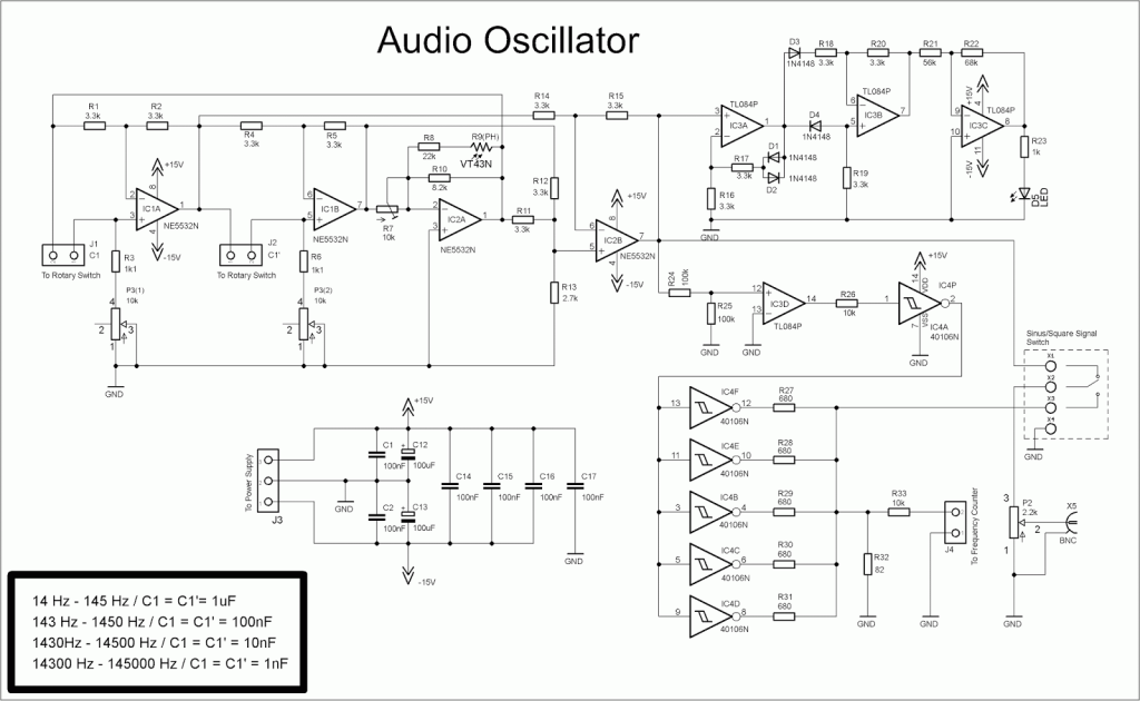
After I finished the oscillator, I made some minor changes in the square signal part of the schematic. I connected five of the inverters in parallel with low value load resistors, thus reducing the influence of the parasitic capacitance of the PCB. The goal is to lower rise and fall times of square signal. Max output voltage in square signal mode is around 5V.

Schematic

Osc9

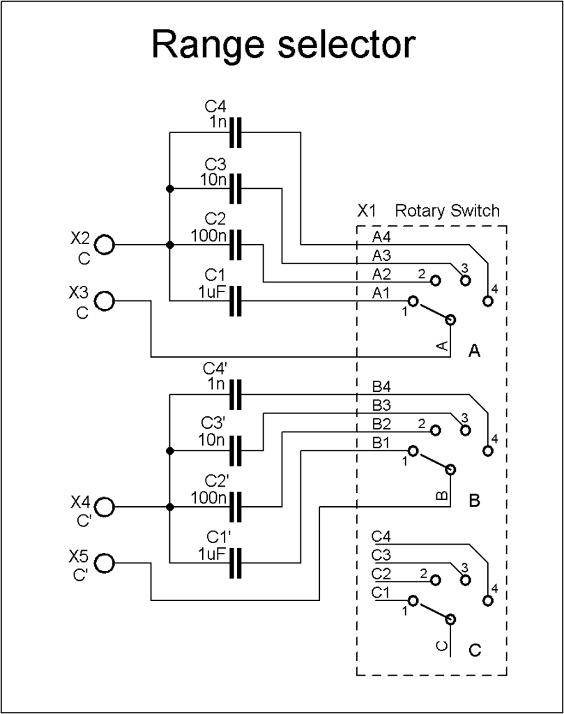
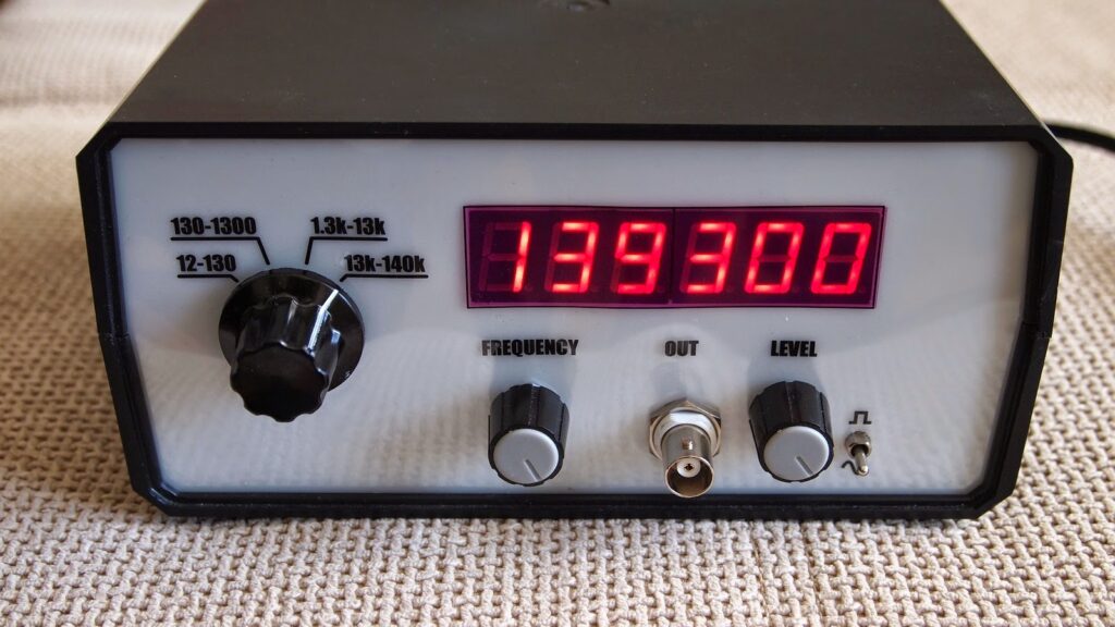
The oscillator have 4 ranges which are switched with external 3-pole/4-position rotary switch, connected this way:

Osc10

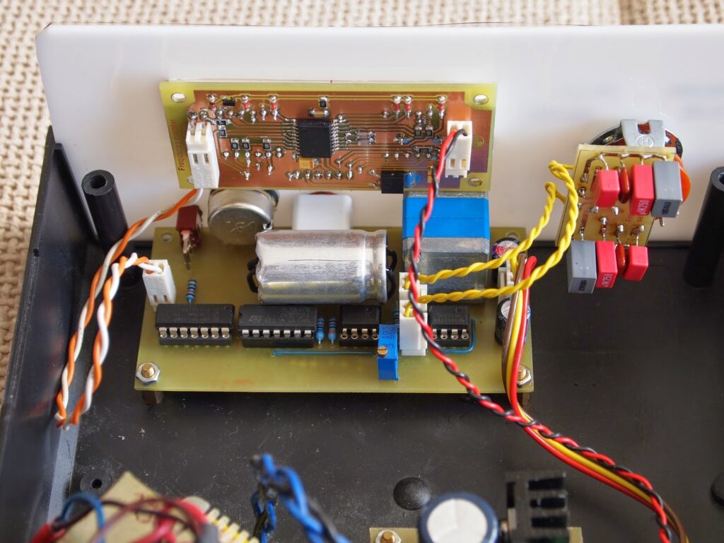
This module is connected via short cables to the respective connectors on the oscillator board.
Notice, that capacitors are soldered from the bottom side of this little board. The leads of the capacitors must be cut clean from the other side of the board for they do not touch the rotary switch

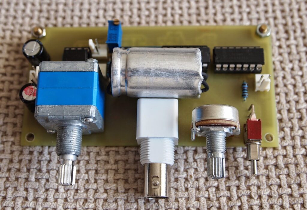
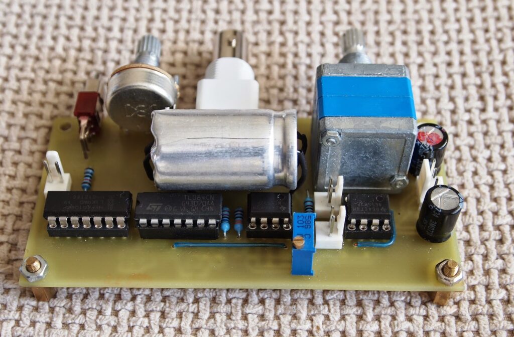
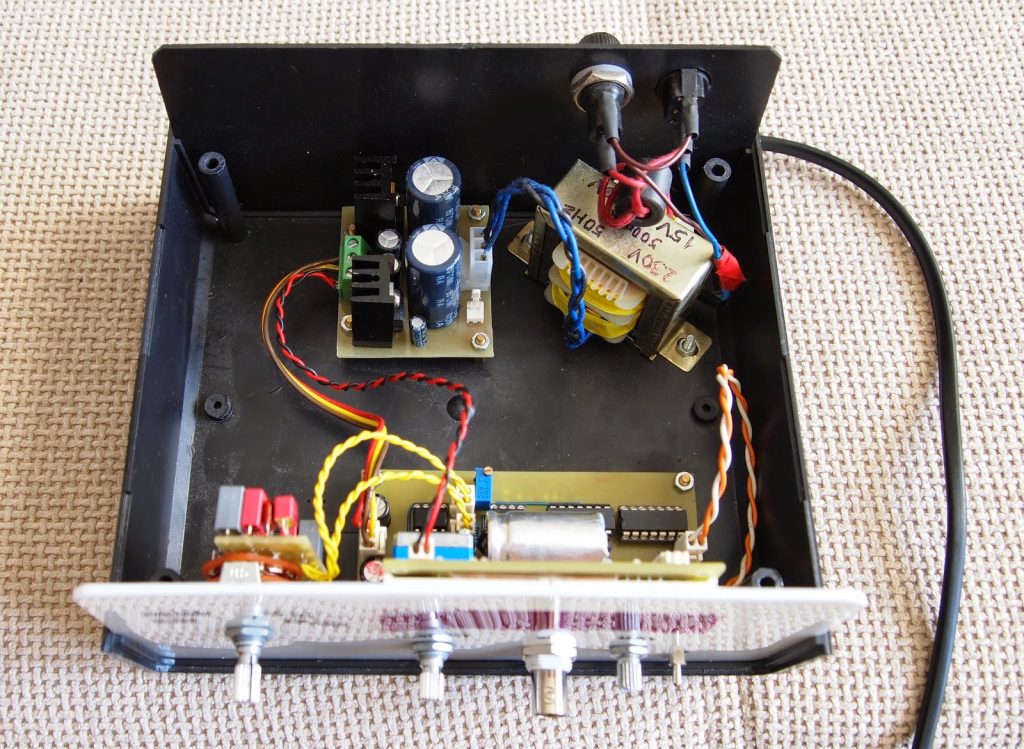
The photoresistor R9 and LED D5 form a negative feedback and must be put together in some isolated enclosure. I used an aluminum casing from a big electrolytic capacitor for this purpose. LED is standard 5mm red and for the photoresistor I used a TESLA brand piece (not sure what is the exact model). Other types of photoresistors should also work.
In the schematic the photoresistor is connected with one resistor (R8) in series and one (R10) in parallel. I found that in my case the oscillator work better without these 2 resistors.

Photos

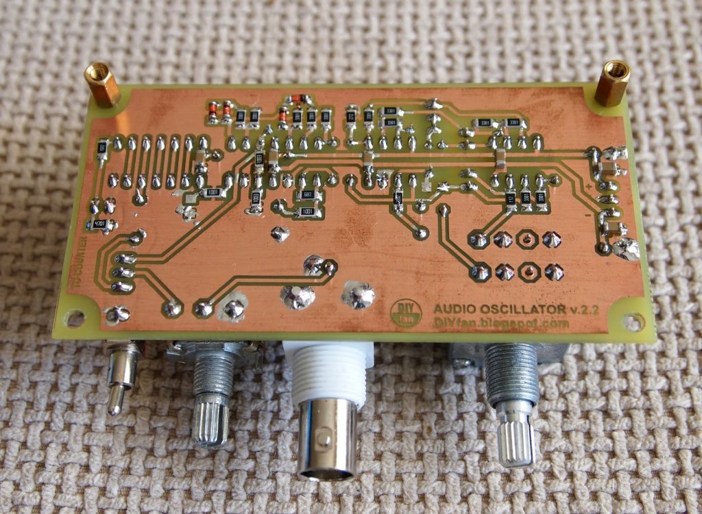
Osc1

Osc2

Osc3

Osc4

Osc5

Osc6

Osc7

Osc8

As you can see, the position of the BNC connector and two knobs is not very convenient. In the last revision of the PCB I switched the positions of the BNC connector and the LEVEL potentiometer.
All in all I am satisfied with the result.

Automotive Chip-On-Glass LCD Dot Matrix Driver

The automotive products are quite recognized nowadays. It brings high demand on automotive chip and other related electronic devices. These demands are diverse, which brings difficulties to automotive developers. In this design, users are provided a modifiable firmware using In-System/In-Application Programming (ISP/IAP) via USB. It features the Vertical Alignment (VA) Chip-On-Glass (COG) display module with integrated backlight. The power supply can be done either via USB or an external power supply. This can also be used for an external VLCD that also provide temperature compensation. Its 100 segment and 18 backplanes allow the system to drive up to 1800 elements for graphic display.
The design is comprised of PCA8539DUG 100 x 18 COG automotive LCD dot matrix driver that generates the drive signals for multiplexed LCD, which in this design it is a Passive Matrix Vertically Aligned (PMVA) negative display providing a very dark background with a very wide and symmetric viewing angle. The NX1117CE low-dropout linear regulator is used to provide 3.3V supply for the backlight and the microcontroller. The LPCXpresso low-cost development platform provides the variety of interfaces with respect to the customer designs or needs. It is a highly integrated software development environment for NXP’s LPC microcontrollers. The JP1 to JP6 are used to select either the I2C – bus interface, or the SPI interface. They need to be all in the same position. The silk screen indicates which position to use for a given interface. The JP7 is a jumper that connects the VLCDOUT and VLCDSENSE to the VLCDIN pin of the PCA8539. It must be placed if the internal voltage generation is used. The JP9 may not have been soldered into the board during manufacturing. Instead, a 0Ω resistor (R2) is mounted, in parallel with this jumper. Removing the 0Ω resistor and mounting the jumper makes it easy to insert a current meter and measure the current consumption to the VDD pins of the PCA8539. After measurements, a jumper header can be inserted. The PMEG3005CT 500mA low VF dual MEGA Schottky barrier rectifier is used for the polarity and stress protection.
The development in automotive is quite helpful to people. It is use to accomplish task, save lives, and protect people from any type of danger. With this new design of automotive LCD, it is expected that automobiles will be able to optimize its usage and capability to serve people

Automotive Chip-On-Glass LCD Dot Matrix Driver – [Link]

TOP PCB Companies