This wireless project is a power transmission system, it works on the principle of magnetic induction. This Wireless Charging system works as the digital switched mode power supply with the transformer, which is separated into two parts: The transformer primary coil is on the transmitter, working as the transmitter coil, and the transformer secondary coil is on the receiver side as the receiver coil. This system works based on magnetic induction, the better coupling between the transmitter coil and receiver coil gain, the better system efficiency. So the receiver coil should be closely and center aligned with the transmitter coil as possible. After the receiver coil receives the power from the transmitter coil by magnetic field, it regulates the received voltage to power the load, and send its operational information to transmitter according to specific protocol by the communication link. Then the system can achieve the closed-loop control, and power the load stably and wirelessly. Continue reading “Wireless Transmitter System”
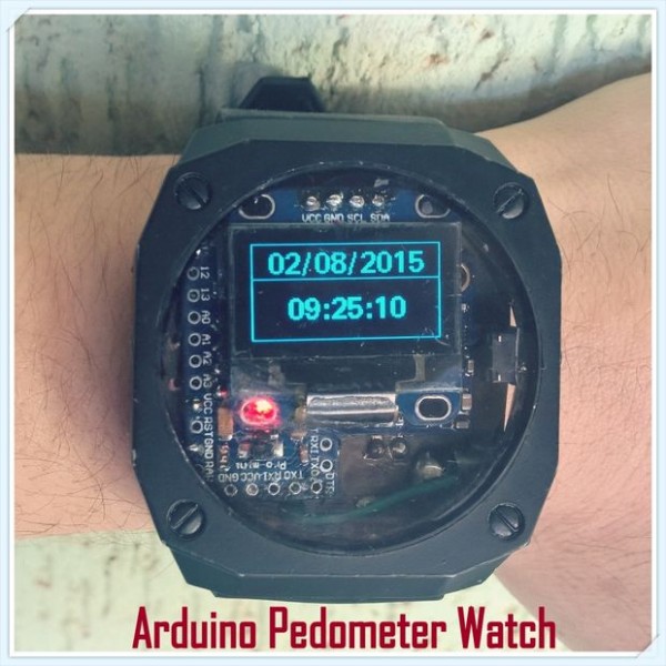
Arduino Watch With Altitude, Temperature, Compass And Pedometer
by benhur.goncalves @ instructables.com:
Hi folks! Last few days I’ve been obsessed with the idea to make my own watch from arduino parts, but something cool I could use and say I did it myself. So I found out there was a sensor board (commonly named GY-87) which had three sensors on it: HMC5883L (compass), BMP085 (pressure, altitude, temperature) and MPU6050 (accelerometer and gyroscope). With it, via I2C, I could add an Arduino Pro Mini, and an I2C Oled Display and make a watch capable of having all this information, plus a pedometer (by analysing accelerometer data).
Arduino Watch With Altitude, Temperature, Compass And Pedometer – [Link]
Externally clocking (and overclocking) AVR MCUs
by nerdralph.blogspot.ca:
People familiar with AVR boards such as Arduinos likely know most AVR MCUs can be clocked from an external crystal connected to 2 of the pins. When the AVR does not need to run at a precise clock frequency, it is also common to clock them from the internal 8Mhz oscillator. Before CPUs were made with internal oscillators or inverting amplifiers for external crystals, they were clocked by an external circuit. Although you won’t see many AVR projects doing this, every AVR I have used supports an external clock option.
Externally clocking (and overclocking) AVR MCUs – [Link]
ESP8266 Weather Station with Arduino
by ohneschuh @ instructables.com:
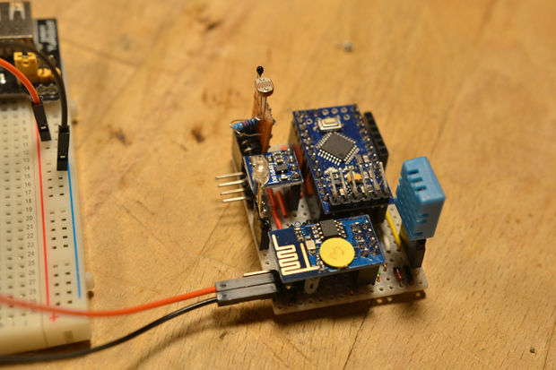
I read about the ESP8266 first in March this year and I didn’t know what to do with. And now I’m really fascinated how easy the connection of an Arduino to the Internet can be. Like others I set up a weather station on a breadboard first and sent data to thingspeak.com. This ends up in a highly condensed stripboard layout and the needed software package.
What are the functionalities?
measure temperature, humidity, pressure and illuminance (brightness)!
send all data to thingspeak
ESP8266 can be turned on and off by Arduino for energy saving
additional digital IOs
Runs on 5 to 12 V
and a lot more
ESP8266 Weather Station with Arduino – [Link]
Pierce Crystal Oscillator Theory and Design
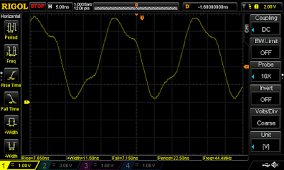
The theory and practical design of a 28MHz discrete Pierce crystal oscillator.
Pierce Crystal Oscillator Theory and Design – [Link]
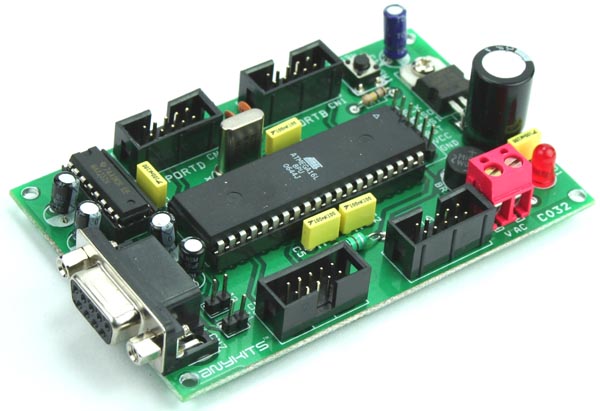
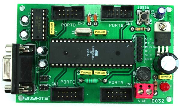
ATMEGA16/32 DEVELOPMENT BOARD
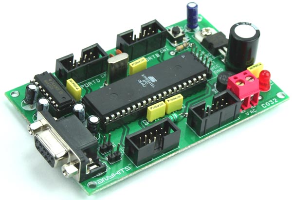
ATmega16/32 Development Board provides a very simple and cost effective platform for prototyping solution. The compact design provides connection to all the pins of the microcontroller for the user.
- Prototyping solution available for 40-pin ATmega series AVR microcontroller from ATMEL
- All the four ports available to the user via standard 10 pin box header connector with supply of 5 VDC for interfacing circuits
- Onboard reset switch for easy reset of the microcontroller
ATMEGA16/32 DEVELOPMENT BOARD – [Link]
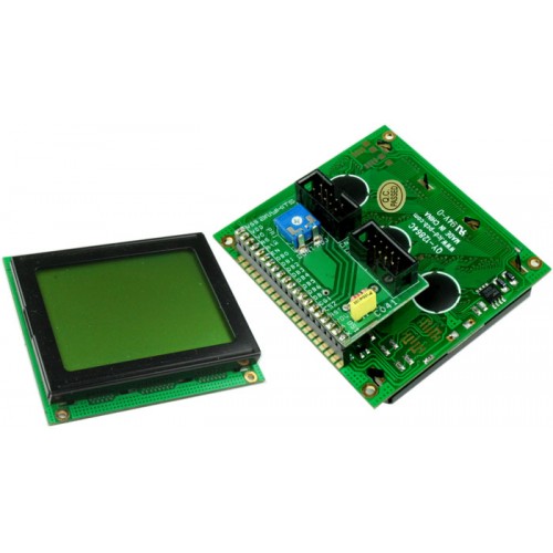
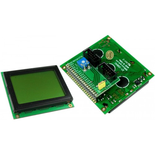
GLCD MODULE
GLCD Adapter Board offers an easy way to interface a standard GLCD to your project.
GLCD MODULE – [Link]
ATmega16/32 Development Board
ATmega16/32 Development Board provides a very simple and cost effective platform for prototyping solution. The compact design provides connection to all the pins of the microcontroller for the user.
- Prototyping solution available for 40-pin ATmega series AVR microcontroller from ATMEL
- All the four ports available to the user via standard 10 pin box header connector with supply of 5 VDC for interfacing circuits
- Onboard reset switch for easy reset of the microcontroller
- ISP (In circuit Serial Programming) connector available for chips with ISP support
- 8 MHz Crystal onboard
- UART level shifter circuit using MAX232 IC, onboard for easy connection of the board to the RS232 devices
- Jumper selectable connection available for connecting the UART level shifter to the port pins
- Onboard voltage regulator available for sourcing regulated 5V @ up to 0.6A voltage to the board and connecting circuit
- Power-On LED indicator
- Four mounting holes of 3.2 mm
- PCB dimensions 64 mm x 101 mm
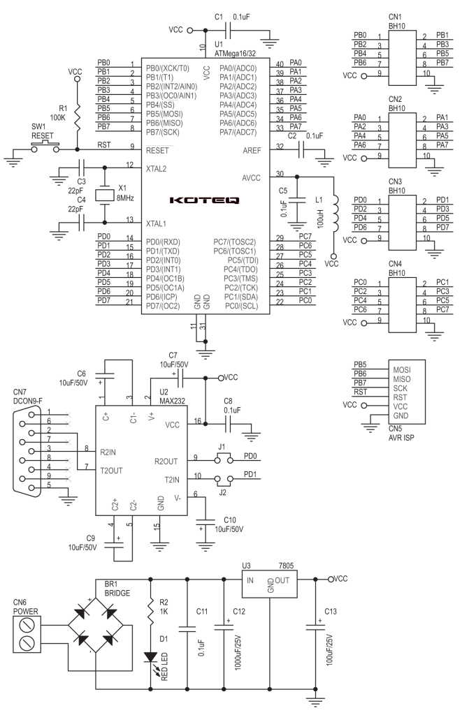
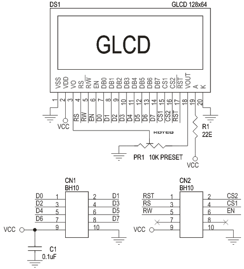
Schematic
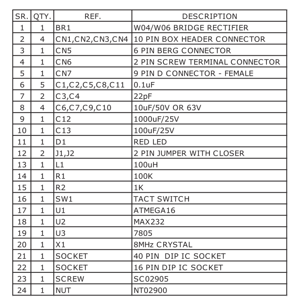
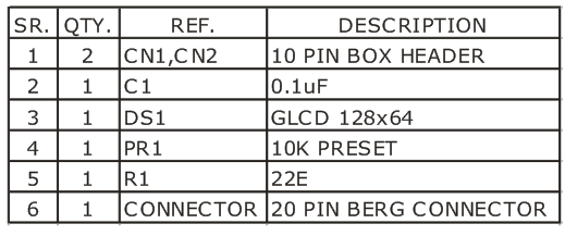
Parts
Connectors
 Photo
Photo
GLCD Module
GLCD Adapter Board offers an easy way to interface a standard GLCD to your project.
- 5 VDC supply sourced through the interfacing Box Header connector
- Two separate box header connector available for interfacing of data bus and control bus to the interfacing unit
- On Board Contrast control Preset also available
- PCB dimensions 52 mm x 33 mm
Schematic
Parts
Narrowband RF Power Amplifier (520MHz)
The RF power amplifier stage is usually the final active block of any electronic system that is transmitting RF power. Relatively low power RF signals are amplified to produce a more powerful signal in order to be transmitted over greater distance. RF output power can range from a few mW to MW, depend by application. RF amplifiers before were all made using vacuum tubes but modern RF amplifier nowadays uses solid state devices like MOSFET, TMOS-FET, Bipolar junction transistors, and IGBT to amplify RF signals.
This circuit features the Freescale AFT05MP075GNR1 RF power LDMOS transistor as its RF amplifier solid state device. With the use of some components and proper board layouting, Freescale was able to create a 70 watts RF power amplifier with a gain of 18.5dB. This circuit requires a 12.5Vdc power supply able to provide the maximum power this LDMOS transistor can give. In this circuit, AFT05MP075GNR1 was configured to amplify RF signal with a carrier frequency of 520MHz suitable for UHF band mobile radio applications.
The Freescale AFT05MP075GNR1 was designed for mobile two-way radio applications with frequencies ranging from 136 to 520 MHz. It can be configured as a narrowband or wideband RF power amplifier. The high gain, ruggedness and broadband performance of this device make it ideal for large-signal, common source amplifier applications in mobile radio equipment. It can operate exceptionally in a very wide temperature range, from -40 to +150 degree Celsius. Though this device handles wideband application, it can still give full power across the band.
Narrowband RF Power Amplifier (520MHz) – [Link]


