Inside the Intel RealSense Gesture Camera

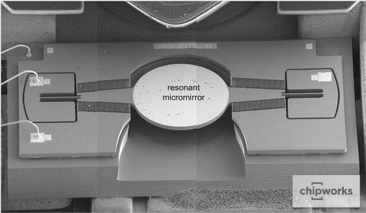
STMicro resonant MEMs device inside intel realsense

by Sinjin Dixon-Warren @ chipworks.com:

The Intel® RealSense™ gesture camera represents another foray by Intel into the consumer products space. The camera has been incorporated into the Lenovo ThinkPad Yoga 15. Intel disclosed at IDF14 that the device is formed using three components: a conventional color CMOS image sensor camera, an infrared images sensor, an infrared light projector (the main focus of this article), plus an image processor. It can also incorporate a pair of microphones.

Inside the Intel RealSense Gesture Camera – [Link]

Even you switch ecologically?

obr1735_p765

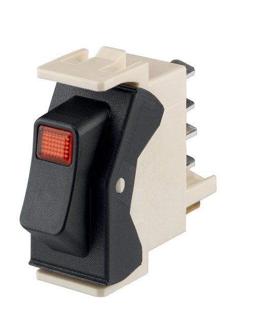
More exactly, we talk about switching-off a device. Marquardt 1550 Eco Switch enables this extraordinarily easily.

Do you know a situation, when a seemingly usual thing is fact not that usual… Whether it´s a car with a hybrid drive or a lot of devices which we meet every day – usually in every segment can be found something “inconspicuous” but in fact unusual and exquisite. This is exactly the case of the 1550 Eco Switch series.At the first sight – a usual rocker switch of this series is able to switch off a device in a pre-defined time or it can be switched off remotely – by a pulse (4A/250V, 10ms). Both cases result in a physical contacts disconnection, what´s advantageous from a safety point of view (total galvanic isolation and overvoltage protection) as well as from a zero power consumption point of view. In case of a remote-off version a given switch can be controlled also by the controlled device itself (which is powered through this switch). In this case it results to self “cut-off” of a device and it can be switched on again only physically by an operator. A typical example of use can be a safety function of temperature monitoring inside a device which is able to switch off itself in case of a fault.

1550 Eco Switch series can be used not only for power supply line. The contacts reliably switching even small DC voltages enable usage also for transition of various control signals and similar.

Detailed information will provide you the Marquardt 1550 Eco Switch datasheet and Marquardt 1550 versions.


Even you switch ecologically? – [Link]

Making A SMD Reflow Oven

FNN6TOQICID5EAF.MEDIUM

by packetbob @ instructables.com:

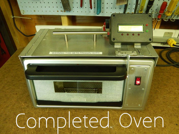
I decided to put together a toaster oven and wanted something that could handle large boards and possibly do small production runs. Doing a web search, you will find many options for toaster oven reflow controllers. They range from one-off designs to DIY boards to full kits. A large number of them are Arduino based. Some controllers just allow the oven to plug in (so you don’t need to take the oven apart) while others integrate completely inside the oven (more work but a much better product in the end).

Making A SMD Reflow Oven – [Link]

Making PCBs with CNC

CodeLock1

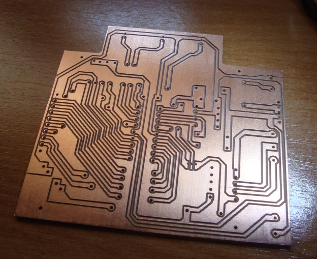
Rui written an article on how to build your own PCBs using a CNC machine. Rui Cabral writes:

The PCB manufacturing method i used before buying my CNC machine was the lithography method and worked as follows:

First i printed the board design on an acetate sheet.

This sheet was placed over a pcb with a light sensitive coat and placed under UV light for several minutes.

The pcb was then immersed in a solution of caustic soda to remove the photo sensitive material that was “damaged” with the UV light.

The pcb was then immersed in a Ferric Chloride solution to remove the copper.

After the copper being removed i then washed the pcb to remove the chemicals and then i needed to cut the plate and finally drill the pads.

Making PCBs with CNC – [Link]

Buck battery charger handles multiple chemistries

4015

by Susan Nordyk @ edn.com:

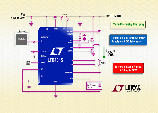
The LTC4015 synchronous step-down battery charger controller from Linear Technology offers charge current of up to 20 A, multiple-chemistry operation, and onboard digital telemetry. The controller transfers power from a variety of input sources, such as wall adapters and solar panels, to a Li-Ion polymer, LiFePO4, or lead-acid battery stack with system load up to 35 V.

Operating over an input voltage range of 4.5 V to 35 V, the LTC4015 provides ±5% charge-current regulation up to 20 A and ±0.5% charge-voltage regulation. While a host microcontroller is required to access the most advanced features of the LTC4015, the use of an I2C port is optional.

Buck battery charger handles multiple chemistries – [Link]

Simple circuit lets you characterize JFETs

296708-simple_circuit_lets_you_characterize_jfets_figure_2

by John Fattaruso @ edn.com:

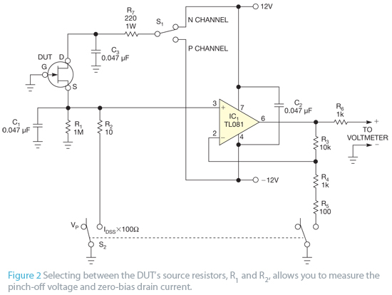
When working with discrete JFETs, designers may need to accommodate a large variation in device parameters for a given transistor type. A square-law equation is usually used as an approximate model for the drain-current characteristic of the JFET: ID=β(VGS−VP)2, where ID is the drain current, VGS is the gate-to-source voltage, β is the transconductance parameter, and VP is the gate pinch-off voltage. With this approximation, the following equation yields the zero-bias drain current at a gate-to-source voltage of 0V: IDSS=βVP 2, where IDSS is the zero-bias drain current.

Simple circuit lets you characterize JFETs – [Link]

2.5A BIPOLAR STEPPER MOTOR DRIVER LV8772E

PIC1

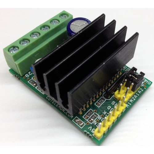
Tiny Board has been designed around LV8772 IC from On-Semi. This driver is capable of micro-step drive and supports 4W 1-2 phase excitation. It has Low on Resistance with motor current selectable in four steps. The board is equipped with unusual condition warning LED and input Pulse Monitor LED. It is most suitable for the drive of a stepping motor for OA, amusements, hobby CNC, 3D printers, automatic machines, linear guides, motion control systems, XY gantry, Camera focus and zoom controller, Mini camera Pan Tilt Head.

2.5A BIPOLAR STEPPER MOTOR DRIVER LV8772E – [Link]

IO expander board

C042

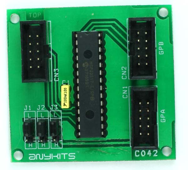
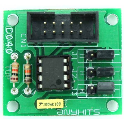
I/O Expander Board offers a convenient way to interface upto 16 I/O pins in your project using SPI/I2C bus.  This kit uses the famous MCP23S17 IO chip from Microhip.

Specifications

  • Supply sourced through the interfacing Box Header connector
  • The kit has 2 separate Box Header type connector for the 16 pins of I/O port and 1 Box Header for interfacing of the PCB with the host controlling circuit
  • Jumper selectable address option is also available for this kit
  • Four mounting holes 3.2 mm each
  • PCB dimensions 58 mm x 54 mm

IO expander board – [Link]

TOP PCB Companies