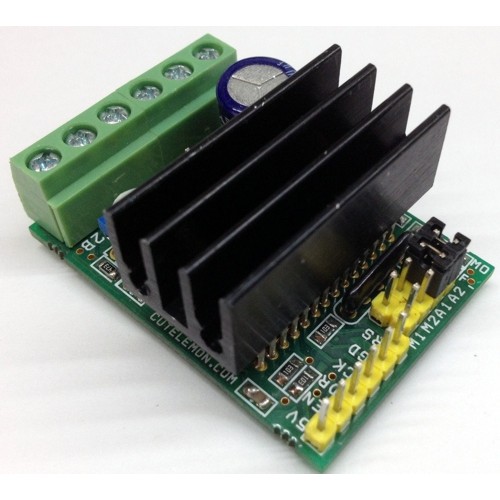
2.5A Bipolar Stepper Motor Driver LV8772E

PIC


Tiny Board has been designed around LV8772 IC from On-Semi. This driver is capable of micro-step drive and supports 4W 1-2 phase excitation. It has Low on Resistance with motor current selectable in four steps. The board is equipped with unusual condition warning LED and input Pulse Monitor LED. It is most suitable for the drive of a stepping motor for OA, amusements, hobby CNC, 3D printers, automatic machines, linear guides, motion control systems, XY gantry, Camera focus and zoom controller, Mini camera Pan Tilt Head.

Specifications

  • Power Supply input 9V to 30V (Max 32V)
  • Output Current 2.5Amps
  • Very low noise and smooth operations
  • Very low noise in slow speed
  • Low on resistance (Total of upper and lower: 0.55ohms)
  • Micro-Step mode can be set to Full-Step, 1/2 Step,1/4,1/16 Steps
  • Motor Current selectable in four steps
  • Output short circuit protection circuit incorporated (IC)
  • Built in thermal shutdown circuit
  • No Control power supply required
  • Input Signals 1. Step (Clock) 2. Direction 3. Enable 4. Reset
  • This Drive default set to enable and reset
  • Current Setting via onboard Preset (Potentiometer)
  • Attenuation ATT1 and ATT2 by Jumpers
  • Two Jumpers for Micro-Step settings
  • On-Board Fault Warning LED
  • On-Board Pulse Input indication LED

Applications

  • Slot Machine
  • Vending Machine
  • Cash Machine
  • PPC (Plain Paper Copier)
  • LBP (Laser Beam Printer)
  • Scanner
  • CNC
  • 3D Printers
  • Textile
  • Camera Pan Tilt Head
  • Camera Focus and Zoom Controller

Chip Enable Functions (Default this pin set to high for normal operation)

  • ST Pin High Operation Mode, Low Disable the drive
  • This IC is switched between standby and operating mode by setting the ST pin, In standby mode, the IC is set to power-save mode and all logic is reset. In addition, the internal regulator circuit and charge pump circuit do not operate in standby mode.

Position detection monitoring function (LED MO, D2)

  • When the excitation position is in the initial position, the Monitor output LED MO D2 placed in the ON State

Setting constant-current control reference current (PR1 Potentiometer)

  • Potentiometer PR1 is to set the Current

RESET Function (Default this pin set to normal operation using pull down resistor R10)

  • Reset Pin Low = Normal Operation, Reset Pin High = Reset State
  • When The RST pin is set to High, the excitation position of the output is forcibly set to the initial state, and the Moni -D2 LED is in ON state, When RST is set to low , the excitation position is advanced by the next STEP input

Output Short Circuit

Output Short-Circuit protection type of IC is latch type to turn off when the output current exceeds the detection current and the state is maintained.  The output short-circuit protection circuit is activated in and event of short-circuit in the output pin. When the short-circuit state continues for a period of time set by the internal timer (approximately 4uS), the output in which short-circuit was first detected are switched to the standby mode, And if the short-circuit state is still detected, all the outputs of the channel are switched to the standby mode, and the state is held, this state is released by setting ST to low.

EMO  Unusual condition warning output pin (Fault LED D1)

This board is provided with EMO (Fault LED) which notifies the CPU of an unusual condition if the protection circuit operates by detecting an unusual condition of the IC, When an unusual condition is detected , the Fault LED D1 is placed in the ON (EMO=Low)

Chopping Frequency

  • F-Chop 10uA/180PF/).5VX2=55Khz 

Connections

CN1: Power Supply In

CN2: Bipolar Stepper Motor Connections

CN6: Control Signal Inputs ( All inputs are TTL Level)

  • Pin1 5V :  DC Aux ( Output)
  • Pin 2 ENB : Enable ( Default set to Enable , Required low input (Pull Down) to disable)
  • Pin3 CK : Clock input to excite the motor ( Pulse Inputs)
  • Pin 4 : GND Ground Signal
  • Pin5 : RS : Reset input

PR1: Onboard Preset (Potentiometer) to set the Current

D1 : Fault LED

D2 : Pulse Monitor LED

CN5 : Aux. Power Supply Output , Supply 24V, 5V Regulated, Ground

M1, M2 : Jumpers to set the Micro-stepping

A1,A2: To Set the Motor Holding Current  (A1=ATT1, A2=ATT2)

MICRO-STEP SETTINGS
SR M1 M2 Micro-Step RESOLUTION
1 LOW LOW FULL STEP
2 HIGH LOW HALF STEP
3 LOW HIGH QUARTER STEP
4 HIGH HIGH 1/16 STEP
JUMPER CLOSED=LOW     I          JUMPER OPEN= HIGH

Current Setting Reference Voltage Attenuation Ratio (A1 & A2 Closed= Low, Open=High)

  • ATT1-A1 Low I    ATT2-A2 Low = 100%
  • ATT1-A1 High I    ATT2-A2 Low = 80%
  • ATT1-A1 Low I    ATT2-A2 High = 50%
  • ATT1-A1 High I    ATT2-A2 High = 20%

The formula used to calculate the output current when using the function for attenuating the VREF input voltage is giving bellow

  • I out+(VREF/%)X(Attenuation Ratio)/RF resistance

Example: At VREF of 1.0V, a reference voltage setting of 100% (ATT1-A1=Low ATT2-A2=Low) and an RF resistance of 0.5 Ohms, the output current is set as shown bellow,

  • I-Out=1.0VX5X100%/0.22Ohms=0.91A

If, in this state (ATT1-A1=High, ATT2-A2=High), I-Out will be as follows:

  • I-Out =0.91AX50%=455Ma

In this way, the output current is attenuated when the motor holding current is supplied so that power can be conserved.

Schematic

SCHEMATIC


Parts

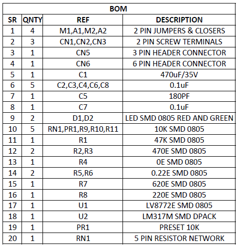
BOM

Photos
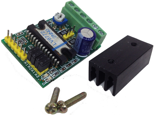
PIC2

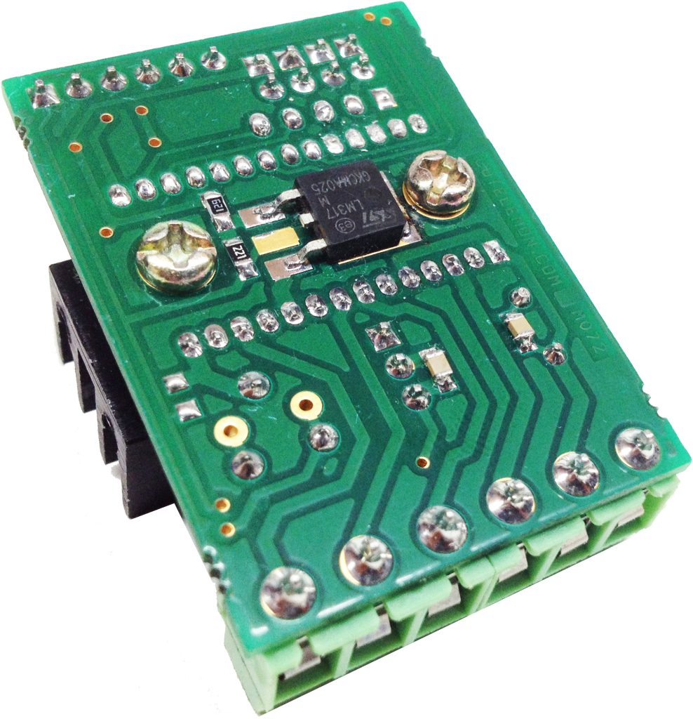
PIC3


Video

LCD Adapter Board

PIC003


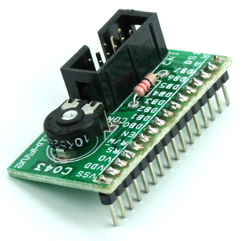
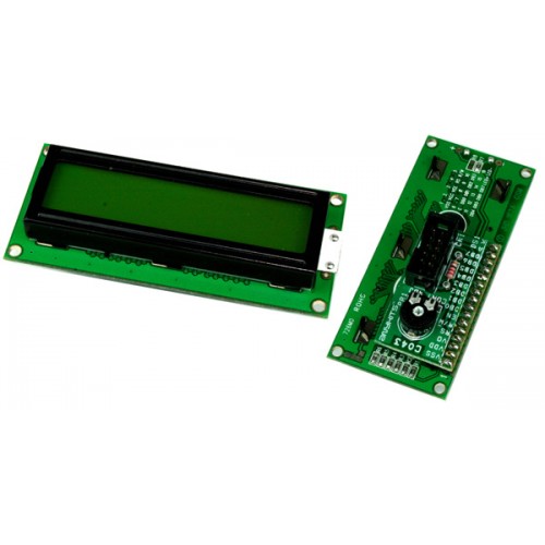
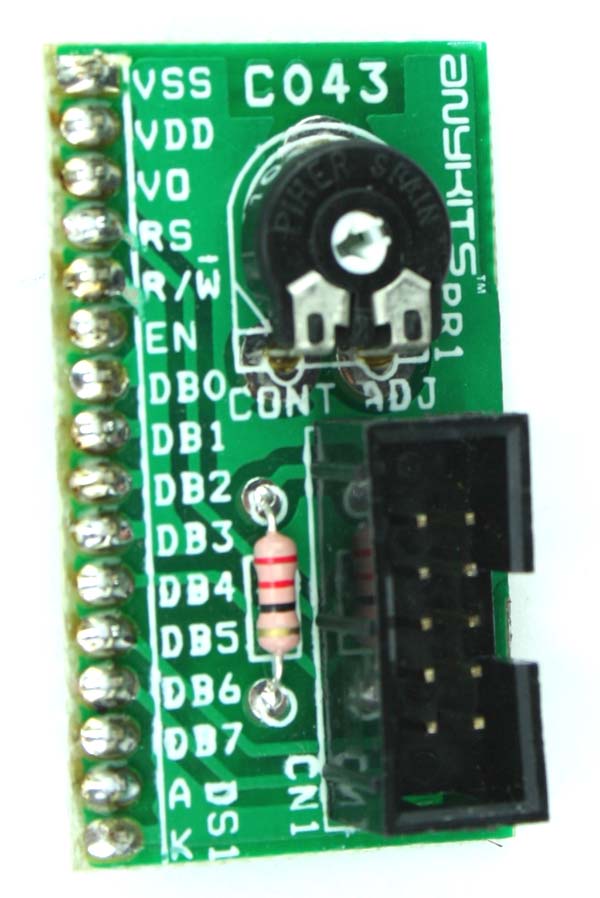
Simple LCD adapter board offers an easy way to interface a standard 16X2 LCD to your project.

Specifications

  • Very Tiny PTH PCB
  • Onboard Preset to set the Contrast
  • Easy interface with 10 PIN Box Header Connector

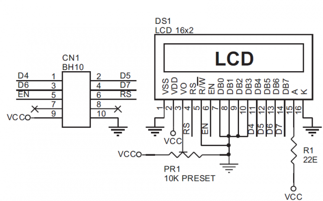
Schematic

SCHEMATIC_LCD_MODULE


Parts

BOM


Photos

PIC001

PIC002

IO Expander Board

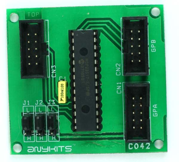
C042


I/O Expander Board offers a convenient way to interface upto 16 I/O pins in your project using SPI/I2C bus.  This kit uses the famous MCP23S17 IO chip from Microhip.

Specifications

  • Supply sourced through the interfacing Box Header connector
  • The kit has 2 separate Box Header type connector for the 16 pins of I/O port and 1 Box Header for interfacing of the PCB with the host controlling circuit
  • Jumper selectable address option is also available for this kit
  • Four mounting holes 3.2 mm each
  • PCB dimensions 58 mm x 54 mm

Schematic

C042


Parts

C042 BOM

EEPROM Module

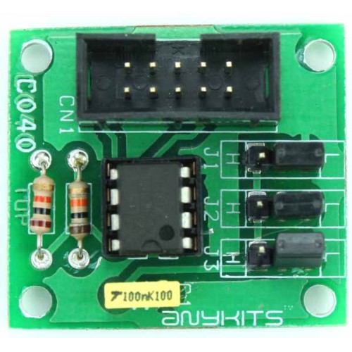
C040-500x500-500x500


EEPROM Add-On Board offers an easy way to interface a standard 24Cxx type I2C EEPROM to your project.

Specifications

  • 5 VDC supply sourced through the interfacing Box Header connector
  • Jumper selectable address option available
  • Four mounting holes 3.2 mm each
  • PCB dimensions 36 mm x 32 mm

Schematic

Schematic


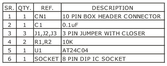
Parts

BOM

16-Bit I2C-Bus LED Dimmer

This project is devised for LED dimming using NXP Semiconductors’ PCA9532 16-Bit I2C-Bus LED dimmer. A lot of solid-state lighting applications require control over the emitted intensity of light for both functional and aesthetic requirements. Some of these applications also require a full dimming capability from fully ON to fully OFF. LED dimming potentially improves light source efficacy and lifetime.

The PCA9532 is an IC that is designed for controlling 16 LEDs over and I2C bus. It also includes the logic to act as an I2C slave device as well as the drive capability for directly driving LEDs. As well as being able to switch each of the LEDs ON and OFF independently, the PCA9532 also has two fully programmable PWM controllers that can be used to control up to 16 LEDs. Each PWM channel has a programmable period ranging from 0.6Hz to 152Hz, and a programmable duty cycle from 0-100%. This means the LEDs can be set to blink steadily and visibly, or dimmed. In this circuit, 13 LEDs are connected on pins LED0-LED12. The 1kΩ pull resistors required are fitted to the 5V supply. Once programmed, the internal oscillator allows the I2C bus to be disconnected from the PCA9532 with the LED continuing to be dimmed, something not possible with normal GPIOs. This enables electronics manufacturers to have supplementary LED dimmers in their systems, while freeing up the microcontroller and the I2C bus for more efficient operation of the system.

The I2C are targeting applications ranging from mobile phones to servers in computing, communication, and networking applications. Having a frequency range of 160Hz to once every 1.6 seconds, with a duty cycle range of completely off to 99.4% on allowing both dimming and blinking of LEDs. These new 2-, 4-, 8-, and 16-bit devices allow designers an easy way to build systems with more dimming LEDs than previously possible using just basic General Purpose I/Os (GPIO) or microcontrollers (MCUs). Manufacturers of applications such as cellphones and servers are increasingly requiring multiple blinking and dimming LEDs for eye-catching keypad lighting applications, as well as practical purposes such as status indication. The new PCA953x LED Dimmers allows more system flexibility by off-loading the LED power consumption and by eliminating the programming of the MCU.

16-Bit I2C-Bus LED Dimmer – [Link]

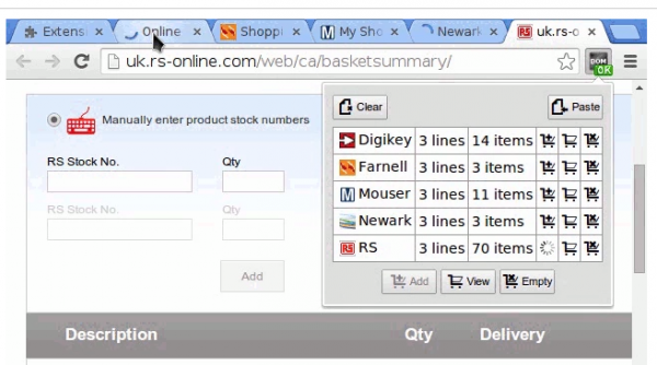
1clickBOM, a browser extension for quick shopping – Firefox version

OneClick-BOM-600x334

Kaspar of Monostable has released a Firefox version of his helpful purchasing tool the 1clickBOM, a browser extension to quickly add electronic components to shopping carts:

1clickBOM, a browser extension for quick shopping – Firefox version – [Link]

LM2596 DC-DC Converter Module Testing

LM2596Module

by Kerry D. Wong:

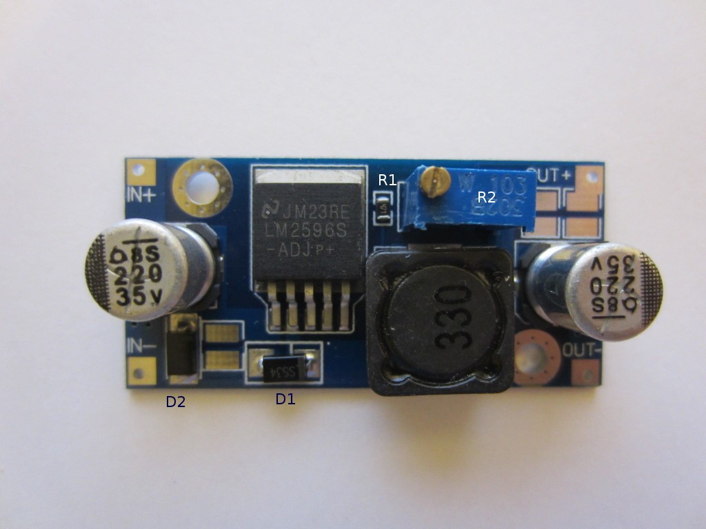
LM2596 based step-down DC-DC converter modules can be bought on eBay quite cheaply for around a dollar each. But how do they perform? Is it safe to use it to power your design? Let’s find out.

According to TI’s website, these LM2596 step-down (buck) regulators are sold for $1.8 each for a quantity of a thousand. So how a finished converter could be sold for just above a dollar each is quite a mystery to me. Anyway, the picture below is the board I received. It appears that there are a few variations to this design (slightly different inductor size or capacitor size/voltage rating, etc.) but they all are largely based on the reference design.

LM2596 DC-DC Converter Module Testing – [Link]

Freaks3D: the World’s First Portable 3D Printer

sadfebxm9m6vrpuq1i1i

Simplified structure. Portable so you can take it anywhere. Quality prints at breaking low price.

Take it wherever you want. The Freaks3D weighs 2.945kg and battery compatible. It is completely portable. Small enough to blend in with any table but large enough to unleash your creativity.

Less is more. Simplified extruded-aluminum beams to ensure sturdy and high-quality performance. The Freaks3D employs v-slot slider system to provide precise seamless positioning.

Quality prints on your desktop. Detailed layer resolution at fast speed. All-metal nozzle head allows PLA/TPU filaments of a rainbow of colors without easy breaks or damage. No pre-heating is needed. Simply feed the filament into the entrance path and the printer will do the rest.

Freaks3D: the World’s First Portable 3D Printer – [Link]

“Non-breakable” interface converter combined with MCU? Wiznet is a solution.

obr1732_1

In the last period we can see, that producers go on the way of processors combined with interface converters grouped into a single chip. Company Wiznet also goes this way.

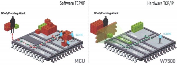
At the end of May 2015, Wiznet launched on the market the new W7500, combining the HW TCP/IP interface converter W5x00 with an MCU. W7500 is a solution combining ARM Cortex-M0, 128kB Flash and the HW TCP/IP. It´s suitable for applications where you use TCP, UDP, IPv4, ICMP, ARP, IGMP and PPPoE. In these devices it´s usually undesired to upgrade SW resulting in resetting a device.MCU W7500 uses HW TCP/IP thus selecting data which arrived from allowed source. W7500 processes only desired data, so “only” 50 MHz is enough. That´s approximately half the power necessary for SW TCP/IP solutions and it also doesn´t require so big Flash and RAM – as illustrated on the picture.

When comparing all data with other MCU, you can notice that with a small power you can make the same things as with the Wiznet solution. This fact is associated with not only reliability and comfort but also with approximately half the price of the chip.

Please note, that parameters mentioned in the table below are substantially lower at SW TCP/IP, while HW TCP/IP is clearly winning.

To make your development easier, Wiznet has its „wikipedia“, where datasheets, schematics, news and user guides can be found.


“Non-breakable” interface converter combined with MCU? Wiznet is a solution – [Link]

Even a small figurine can play a big performance

obr1730_uvod

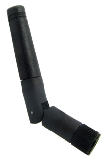
New aerial from 2J will surely not surprise you by its size, however features of the antenna are worth noticing.

2JW035 antenna measures only 52,5mm and is intended for WiFi and Bluetooth devices in 2.4 a 5GHz bands. The gain is 5dBi and the VSWR value is below 2.6:1. A big advantage of this antenna is a possibility of its versatile placing, as it contains a hinge.
So as to suit various customers´ requirements, the producer offers a possibility to order this antenna with three various connectors:

  • 2JW035-C20Nb is equipped with hexagonal black SMA connector
  • 2JW035-C675 is equipped with a round SMA connector
  • 2JW035-C442, which is also our standard stock type is equipped with a round black reverse-polarity SMA connector (RP).

For special applications, there´s also a possibility to order this antenna in a custom specified colour.

Detailed information can be found in the 2JW035 datasheet.


Even a small figurine can play a big performance – [Link]

TOP PCB Companies