Site enables detailed component comparisons

gpiomicsf2

by Sagar Savant @ edn.com:

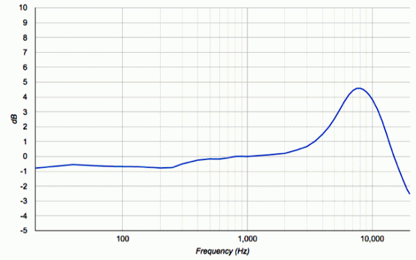
Choosing components is a series of time-consuming tasks, from surveying the market for possible candidates to properly evaluating performance. As a hardware engineer who has worked in Silicon Valley for 10 years, I have spent significant time developing test plans and specs, building fixtures, and testing components. One of the reasons comparing components takes a long time is because you can’t always rely on datasheets to give you the information you need. The problem with datasheets is that they only tell you the story the vendor of the component wants. If an IC characteristic is better under specific conditions, you can be sure the vendor will showcase their components under those conditions.

Site enables detailed component comparisons – [Link]

Do you know, what´s a top-class programmable power supply capable of?

obr1729_1

If you need to simulate overvoltage, slow start, fluctuations and other situations, which may occur in real life, then the TDK Lambda power supplies won´t disappoint you.

Imagine a laboratory (testing) power supply able to provide a virtually any function. Switching on, drop-out, repeated switch-on and many other functions, by which we can test our product in a „single shot“ – those are programmable laboratory power supplies from company TDK Lambda. Perhaps the biggest advantage of programmable power supply is the fact, that there´s no need to adjust, watch, set at testing itself. It´s obvious that this sophisticated device is feelingly more expensive than usual laboratory power supplies, however it´s able to bring enormous time savings and reliability into your work.
In majority of cases it´s possible to reach simulation of a real-life voltage fluctuations, dropouts, disturbances,… This „dynamic“ testing is also able to discover the risk of „freezing“ of your product (undervoltage lockout) at a short-time undervoltage..

Company TDK Lambda belongs to the very top in this segment and its devices provide a literally unlimited possibilities of usage, configuration and control. Whether it´s extremely fast response, possibility of a parallel operation of several units, control over LAN,USB, RS485, GPIB,… almost all possibilities and options known in this field can be found in the TDK Lambda power supplies.

Main series:

  • Z+ (200-800W) – extraordinarily low and compact series. Arbitrary functions generator with 16 bit resolution (+ inner memory), max. output voltage 10-650 VDC. RS232/485, USB and analogue interface. Active PFC (typically 0,99). Advanced parallel master/slave mode.
  • ZUP (200-800W) – max. out voltage 6-120V, max 132A. CC/CV, software calibration, last setting memory, active PFC. RS232/485 and analogue interface.
  • GENESYS (750-15000W) – extraordinary reliability and power. Max 650V, max 1000A. Auto-restart or safe start (user selectable). Last setting memory, available in four sizes – GENH, GEN 1U, GEN 2U and GEN 3U. Optional USB or LAN interface and further accessories.

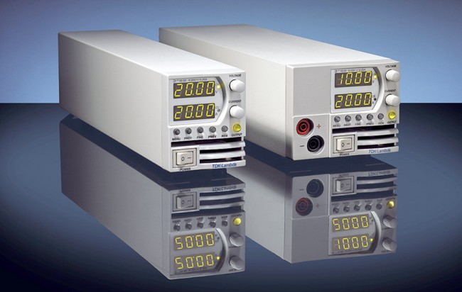
Possibilities of power supplies are really extensive what´s illustrated in enclosed pictures. Detailed information will provide you the catalogue of programmable laboratory power supplies as well as in the TDK Lambda powers supplies and DC-DC converters brochure.

We´re able to supply you TDK Lambda products within 4-12 weeks at advantageous conditions.

Do you know, what´s a top-class programmable power supply capable of? – [Link]

Environmental Alert System

FVQ4K2JICBRY6LJ.MEDIUM

by Aleator777:

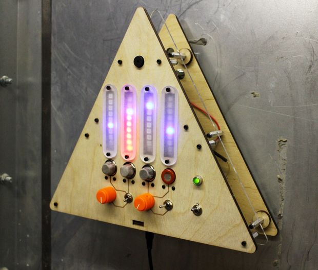
What’s that smell? It’s noxious gas of course! If you’re in an environment where there’s a possibility of gaseous release of which you’d rather not breathe, why not build an automatic system for sensing and alerting you? The design for the Environmental Alert System is driven by my motivation to understand the concentrations of different chemicals in the air. The unit consists of an array of four gas sensors (one each for methane, propane, carbon monoxide, and smoke) connected to an Intel Edison for wireless detection and alerting. While no substitute for a proper commercial chemical detection system, the EAS makes for a great weekend project!

Environmental Alert System – [Link]

Make an Apple Watch Door Unlocker

make-spacelock-completed-board-e1433795851718

Here’s how to automagically open doors at home or at work with a tap on your wrist. By Marc Jensen, James Squires and Shawn Roske:

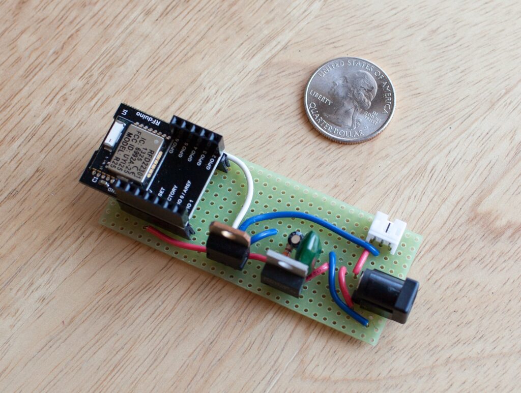
What’s an Apple Watch good for? How about unlocking doors with just a tap on an app? We figured out how do something no one else has done for under 150 bucks, using standard door-strike hardware, our custom app, and a tiny RFduino microcontroller. In this Weekend Project we’ll show you exactly how to do it.

Make an Apple Watch Door Unlocker – [Link]

Nixie Tube Clock

20150525_195643

by Pete Mills :

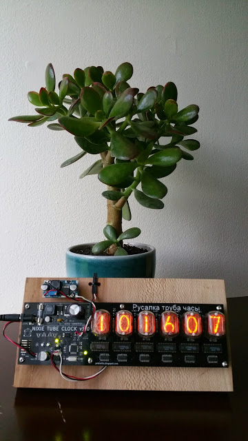
If you’ve poked around the internets where electronics hobbyists collect, it is likely that you are acutely aware of our incontrovertible affinity for building timekeeping clocks. It is similarly unlikely that you have been able to evade the plenitude of nixie tube based projects. There is a reason for this.

Nixie tubes are cool. They have great aesthetic appeal with their difficult-to-photograph, warm orange glow, and dem curvy numerals. They add an organic je ne sais quoi to a hobby with ostensibly digital design cues. Further, they pose technical challenges in the way of producing and switching the ~175 V DC needed to light each tube element. And as far as I am aware, there are no new nixie tubes being produced; as such, procurement can be a challenge unto itself. My N.O.S. nixies came from Russia thru Ebay, and only 3 were duds. Incidentally the seller replaced those 3, FOC.

Nixie Tube Clock – [Link]

DE1-SoC Development Board from Terasic

de1_soc-150x136

by Joel Bodenmann:

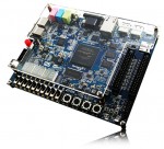
The DE1-SoC board is populated with a six digit 7-segment display. All digits are connected to the FPGA. Therefore, in order to control the 7-segment display out of the Linux userspace code, one has to create a new component in QSys that is connected to the AMBA-AXI bus.
But first of all, please note that this is a blog post, not a comprehensive tutorial. The text below does not replace the official Altera documentation. Furthermore, the post does just show some code snippets. However, the fully working project can be found as a download at the very bottom.

DE1-SoC Development Board from Terasic – [Link]

Homemade breadboard

IMG_2108

by robertgawron.blogspot.com:

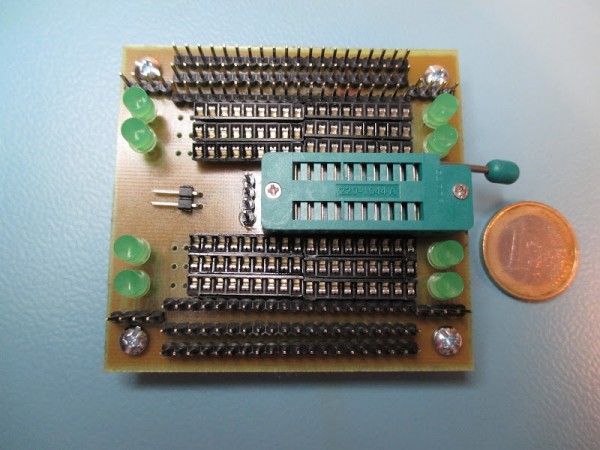
A breadboard can be also made at home, from one side, it will be more expensive than those on the markets, but for another side, it’s possible to add commonly used elements, like LEDs, switches, or other things, for example I added a precision IC socket that makes putting in and out of ICs much easier. Choosing what to put there is a bit like a making homemade pizza, one can put anything he likes (and what he has currently in the fridge).

Homemade breadboard – [Link]


Electronics-Lab.com New Design is Launched

electronicslab_new

We are happy to deploy our new design here on Electronics-Lab.com. We hope you like it and feel free to leave your feedback.

Forum conversion is also done from SMF to IPBoard, but some posts, members and attachments where not able to be converted. If you are unable to login with your old details please register again on the new community.

If you are looking for something and you can’t find it be sure to use Google search from or search using the blog’s search form.

Unipolar 4-Phase Stepper Motor Controller


C055_1


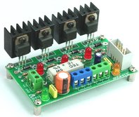
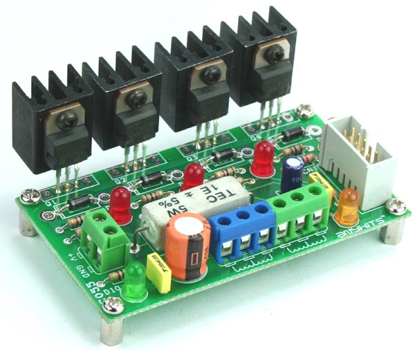
This project is a 4-phase unipolar stepper motor controller.

Description

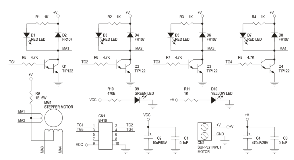
Unipolar 4-Phase Stepper Motor Controller Board will help you control a Stepper Motor or 4 individual Solenoids. This circuit consisting of transistors that serve as current amplifier and also diode to prevent damaging back EMF, circuit uses Darlington transistors to provide high current capacity to unipolar stepper motor. Just provide sequence of pulse using Micro-Controller or descript circuit to roll out the unipolar motor. On board High Watt resistor to control the current, value of the resistor can be set as per your load current requirement.

Specifications

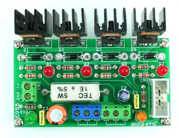
  • Box Header (IDC) connector provides for easy interfacing option
  • Separate LED indicator for individual Phase
  • Screw terminal connector for easy connection of output load and power supply input
  • Power-On LED indicator
  • Four mounting holes of 3.2 mm each
  • PCB dimensions 86 mm x 49 mm

Schematic

SCHEMATIC


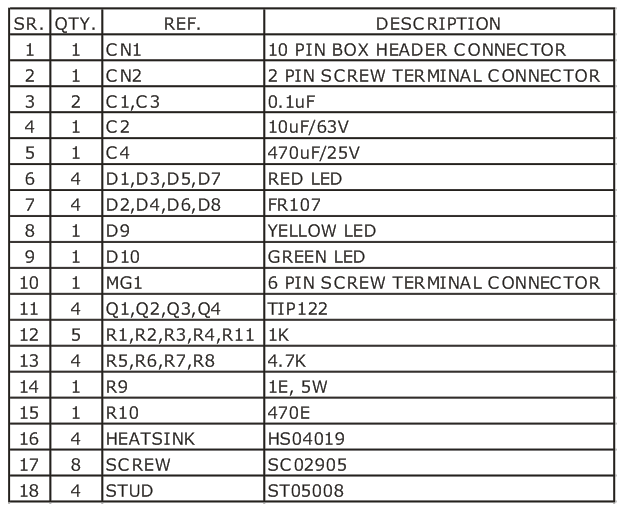
Parts List

BOM

Gerber View

Photo

C055

TIP122 Datasheet

DS1307 Real Time Clock Module

C053


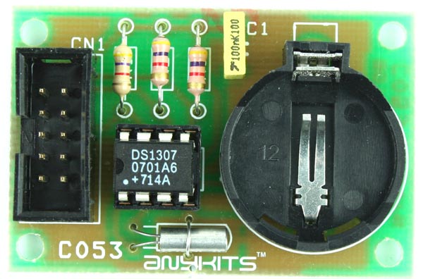
This project is a Real Time Clock based on SD1307 RTC

Description

RTC Add-On Board offers an easy way to interface a standard I2C RTC IC type DS1307, into your project.

Specifications

  •  5 VDC supply sourced through the interfacing Box Header connector.
  • Battery backup for the RTC board available on the PCB
  • Four mounting holes of 3.2 mm each
  • PCB dimensions 50 mm x 33 mm

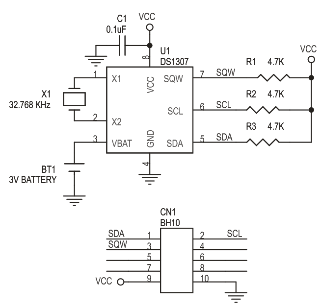
Schematic

SCHEMATIC


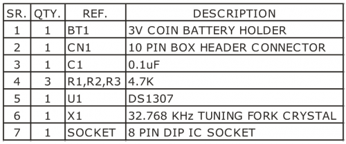
Parts List

BOM


TOP PCB Companies