NiCad-NiMh Battery Monitor

NICAD_NIMH_BATTERY_MONITOR


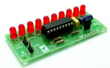
This project is a NiCad-NiMh Battery Monitor based on LM3914 IC

Description

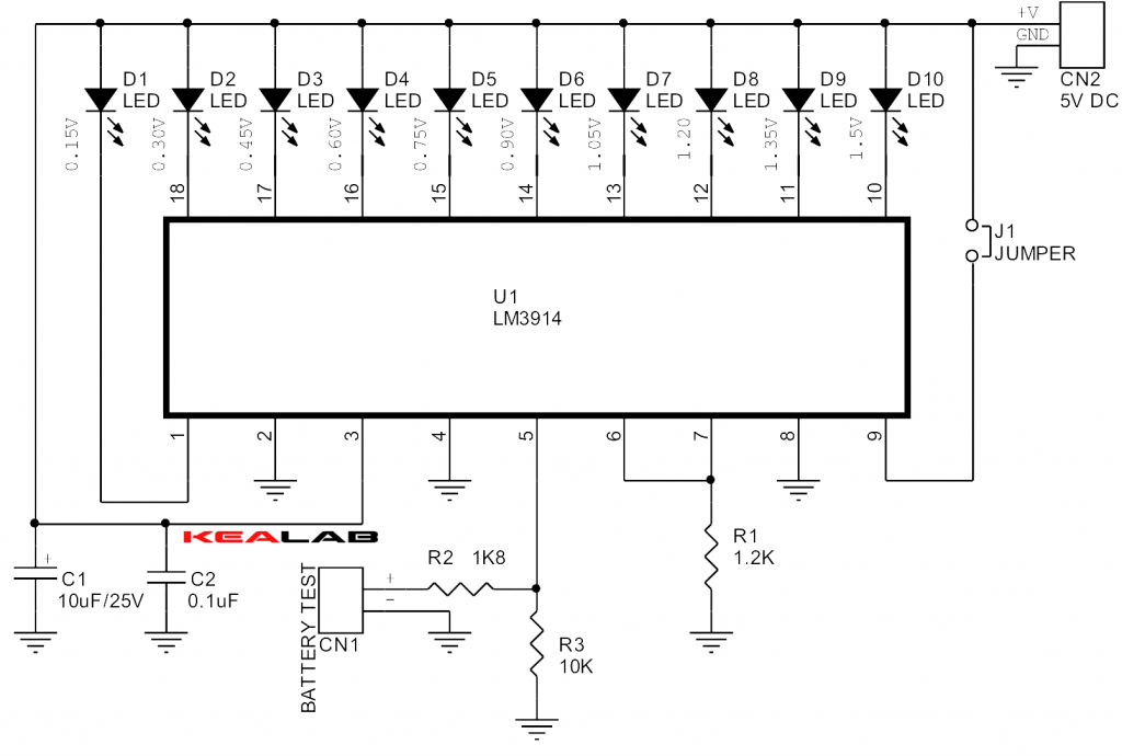
The simple project can be used as test gear. Its easy way to monitor the battery voltages, especially dry cell, NICAD, NIMH, supply up to 1.5 Voltage. Battery Monitor range 0.15V to 1.5V. The project is built around Texas instruments LM3914, The LM3914 senses the voltage levels of the battery and drives the 10 light emitting diodes based on the voltage detected on input connector. Circuit works on 5V DC. J1 Jumper is used to select the DOT mode or bar graph mode.

Schematic

NICAD_NIMH_BATTERY_MONITOR_SCHEMATIC


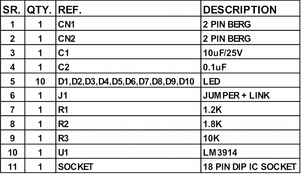
Parts

NICAD_NIMH_BATTERY_MONITOR_BOM


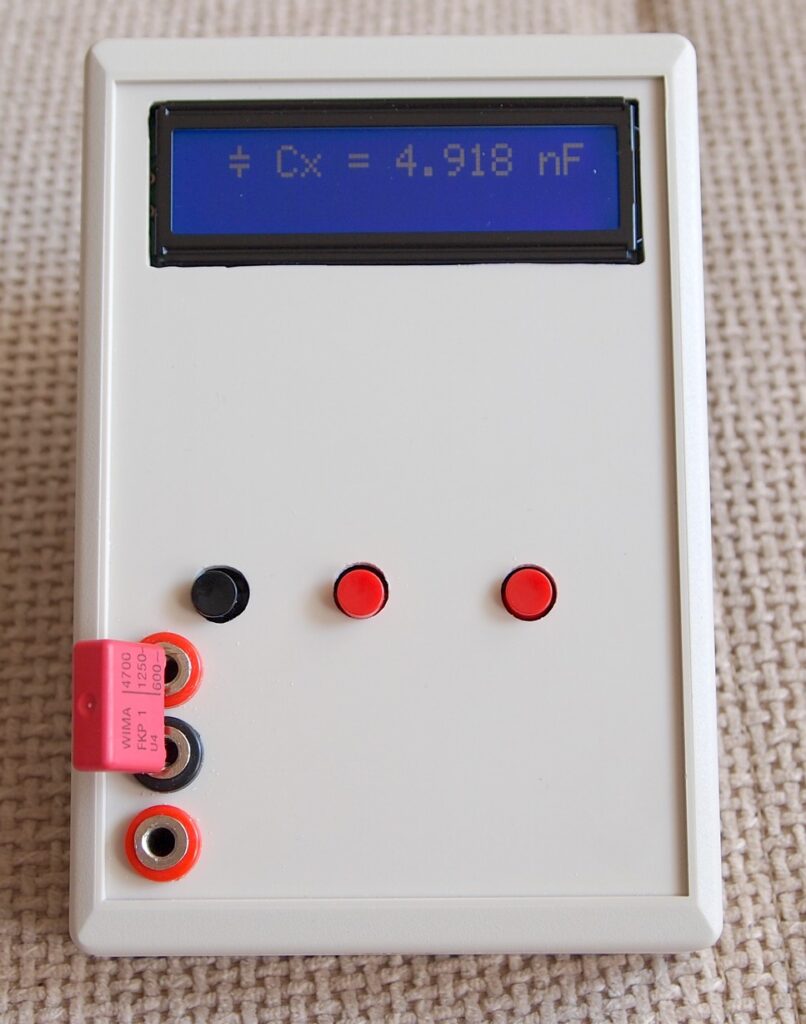
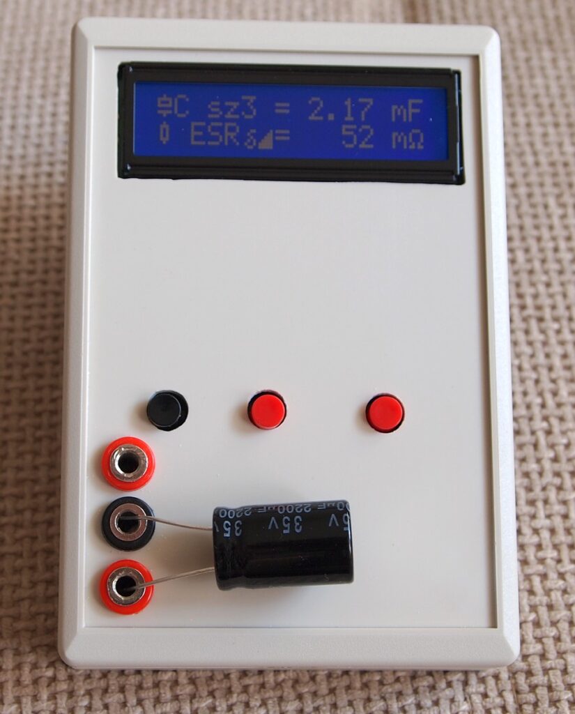
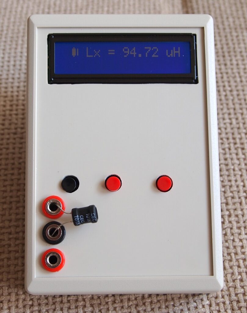
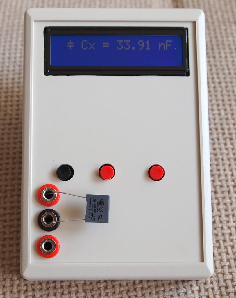
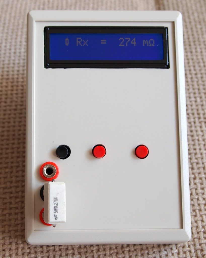
Advanced LC meter

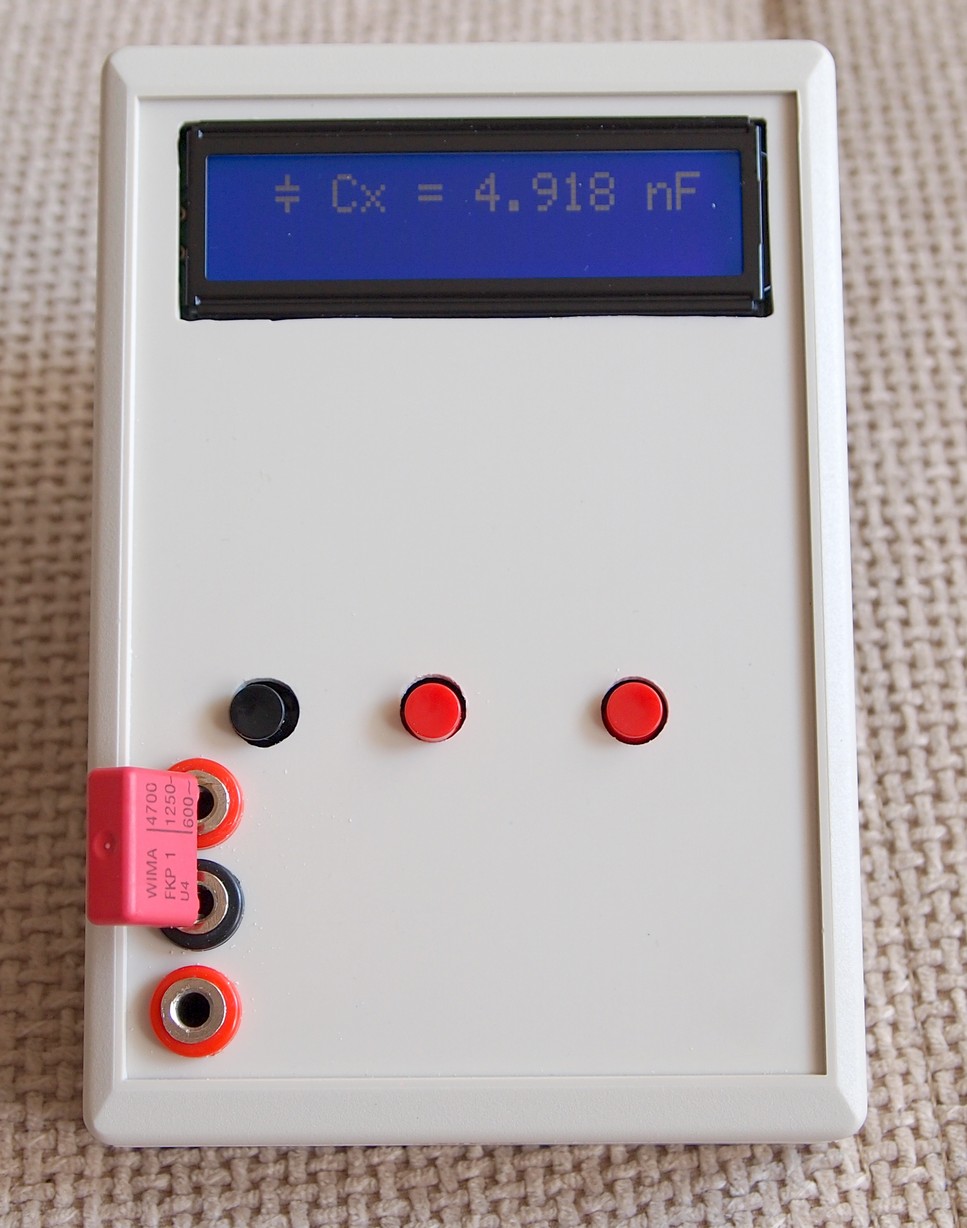
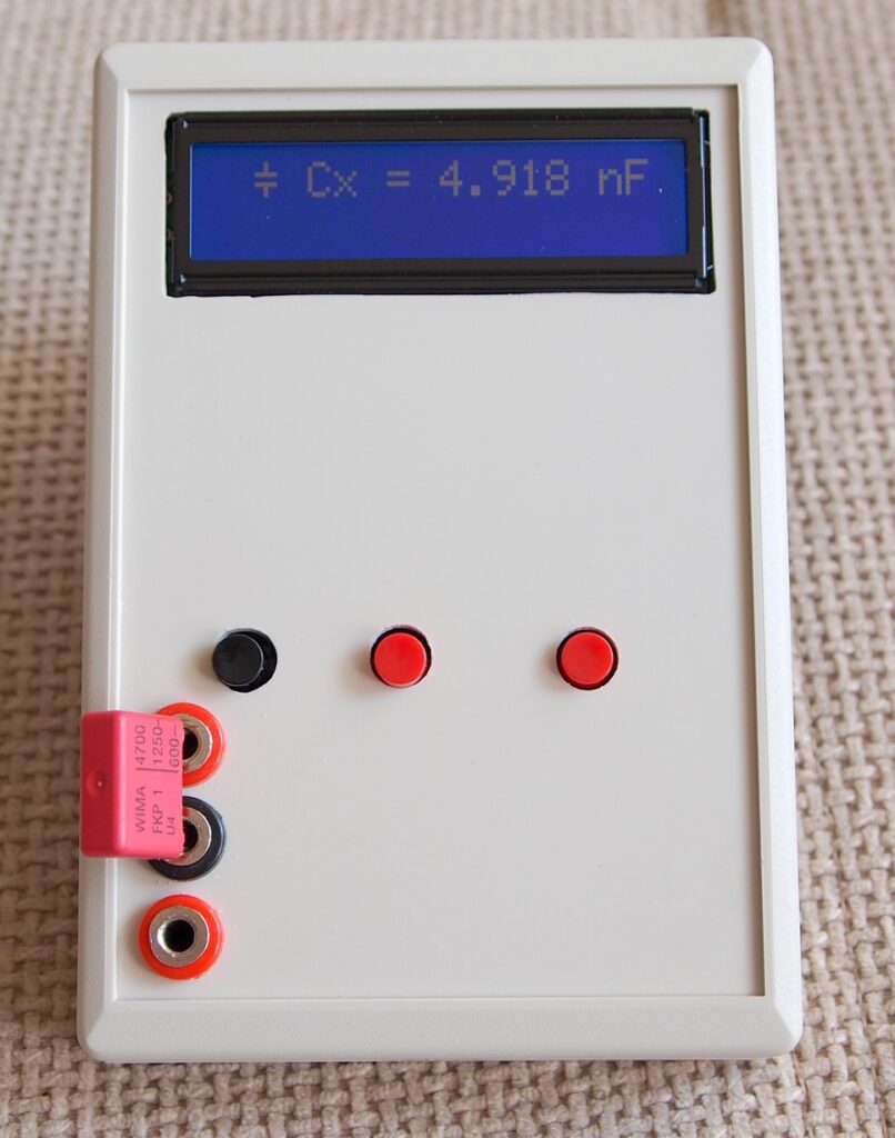
LCM3(2)


This project is an advanced LCR meter based on PIC16F690 microcontroller.

Description

After finishing my last project – “Simple LC meter“, there were some discussions in the forum I am a member of, that ability to measure electrolytic capacitors would be very useful in this type of device.

I searched the Web and found a very nice project named LCM3 on this Hungarian site: hobbielektronika.hu . I love Hungarian rock since my school days, but I don’t know a word in Hungarian 🙁 . So, I searched the Web again, this time for this specific project and found a Russian forum where the project was discussed in details and I got more useful information about parts, settings and so on.

Specifications of the LCM3 are (according to authors of the project):

  • Capacitors: from 1pF to 1nF – resolution: 0.1pF, accuracy: 1% – from 1nF to 100nF – resolution: 1pF, accuracy: 1% – from 100nF to 1uF – resolution 1nF, accuracy: 2.5%
  • Electrolytic capacitors: from 100nF to 100 000uF – resolution 1nF, accuracy: 5%
  • Inductance:from 10nH to 20H – resolution 10nH, accuracy: 5%
  • Resistance: from 1mOhm to 0.5Ohm – resolution 1mOhm, accuracy: 5%

Download .HEX files here

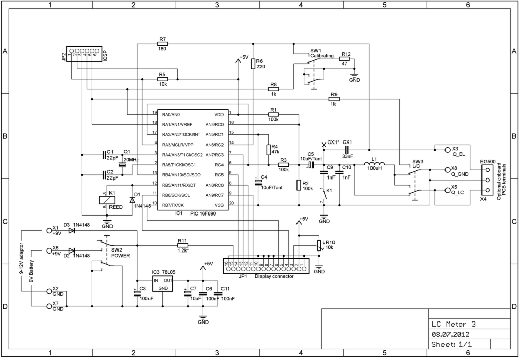
Schematic

So, I put the schematic in Eagle and this is the result:

LCM3 (schem)

PCB

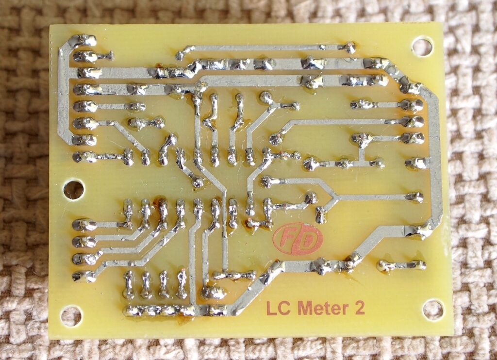
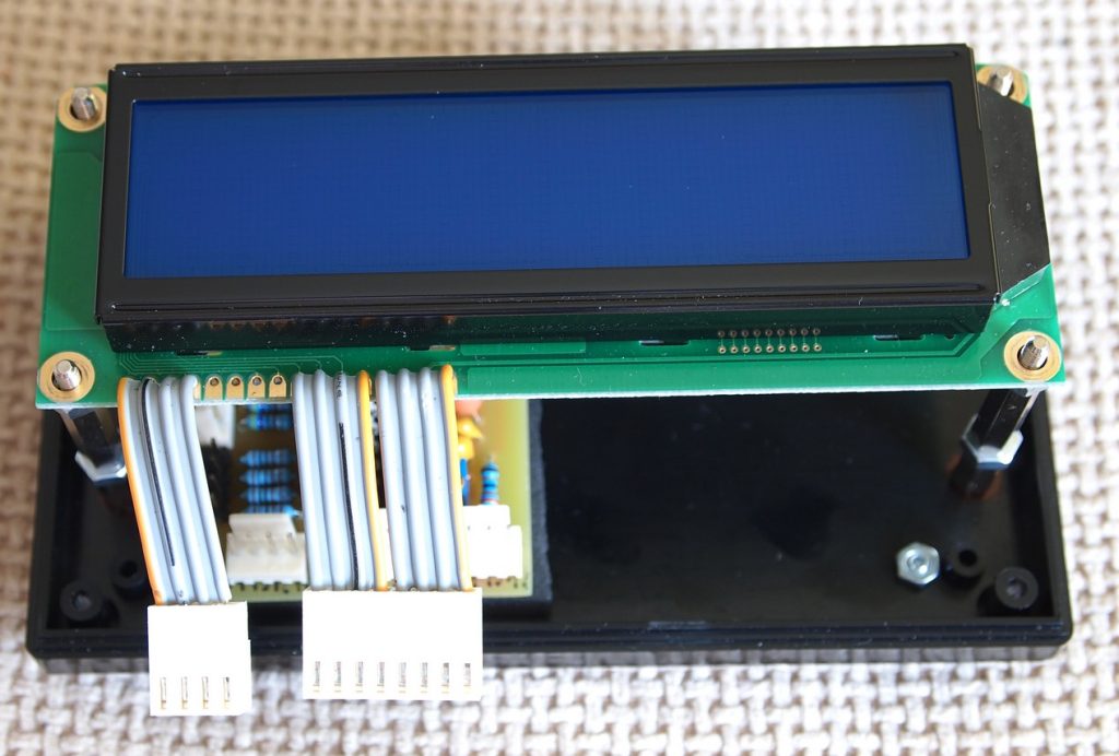
As usual I designed a new PCB. The PCB is designed in such a way, that it is possible to mount the LCD display on top of the board. The multiturn trimmer for adjusting the contrast is bellow the display, so it must be of this type : Тhere is also an option for mounting a 3-pin terminal connector, so it’s possible to use the whole device without an enclosure.

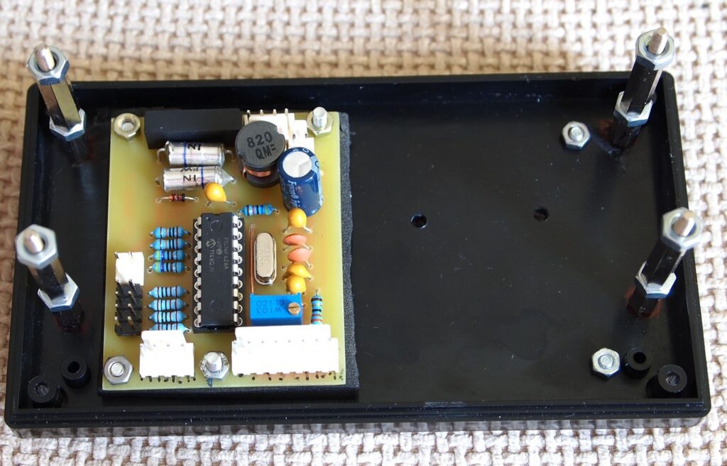
All resistors are 1% metal film. Two 1nF capacitors are 1% styroflex. CX1 – 33nF is also critical – this must be polypropylene high voltage capacitor. I tried with two types: 10% X2 275Vac and Panasonic 3% 800V – worked fine with both. The inductor must be with low Rdc. There is a connector for a separate adapter, which bypasses the ON/OFF button. Maybe on next revision of PCB I would add an onboard power connector. If the device is powered with external power adapter, you may increase back light current by decreasing the value of the resistor R11. You must consult with the datasheet of the display to select a proper value of the resistor.

Capacitors MUST be discharged before measurement or there is a danger of destroying the chip.

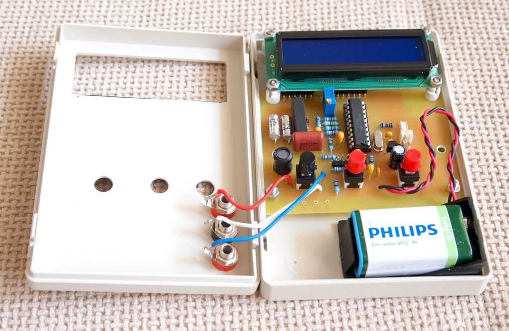
Photos

LCM3(1)


LCM3(2)

LCM3(3)

LCM3(4)

LCM3(5)

LCM3(6)

LCM3(7)

LCM3(8)

LCM3(9)

Simple LC meter

LCmeter_5


This project is a simple LC meter based on PIC16F682A mcu.

Description

Here is another piece of laboratory equipment – LC meter. This type of meter, especially L meter is hard to find in cheap commercial multimeters.

Schematic of this one came from this web page:https://sites.google.com/site/vk3bhr/home/index2-html.

It uses PIC microcontroller 16F628A, and because I recently acquired a PIC programmer, I decided to test it with this project. Following the above link you will find the original schematic, PCB, source and HEX files for programing the microcontroller and detailed description.

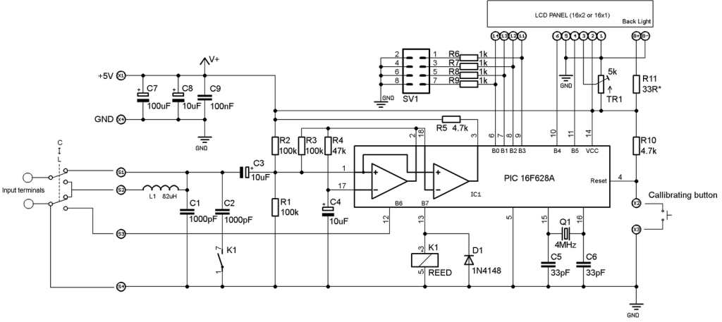
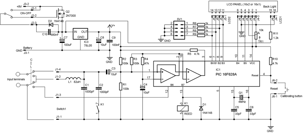
Here is my adaptation of the schematic:

I removed the 7805 regulator, because I decided to use a 5V adapter from Sony mobile phone.

In the schematic, trimmer-potentiometer is 5k, but actually I put 10k, after consulting with the datasheet of the LCD module I bought. All three 10uF capacitors are tantalum and C7 – 100uF actually is 1000uF. Two 1000pF capacitors are styroflex 1% and inductor is 82uH. Total consumption (with back light) of the device is 30mA.

R11 limits the back light current and must be calculated according to the actual LCD module used.

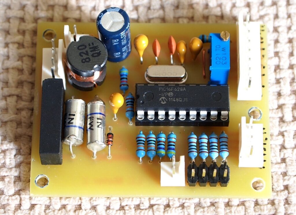
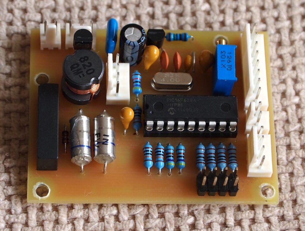
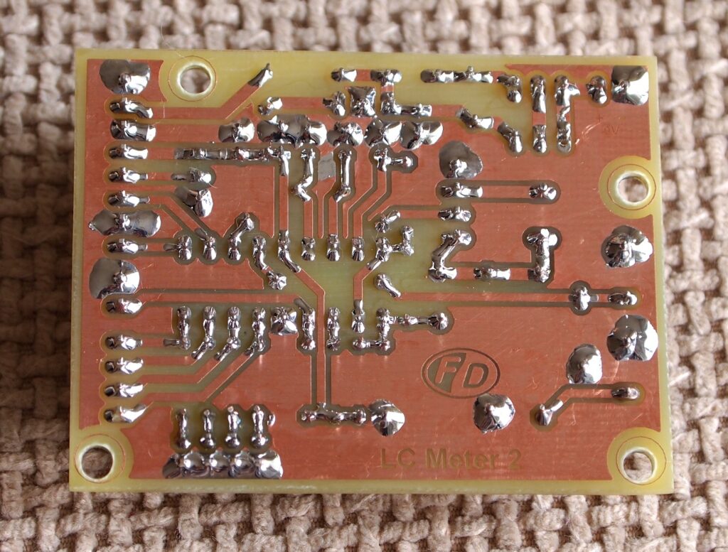
I used the original PCB as a starting point and modified it to suit better to my components.

Here is the result:

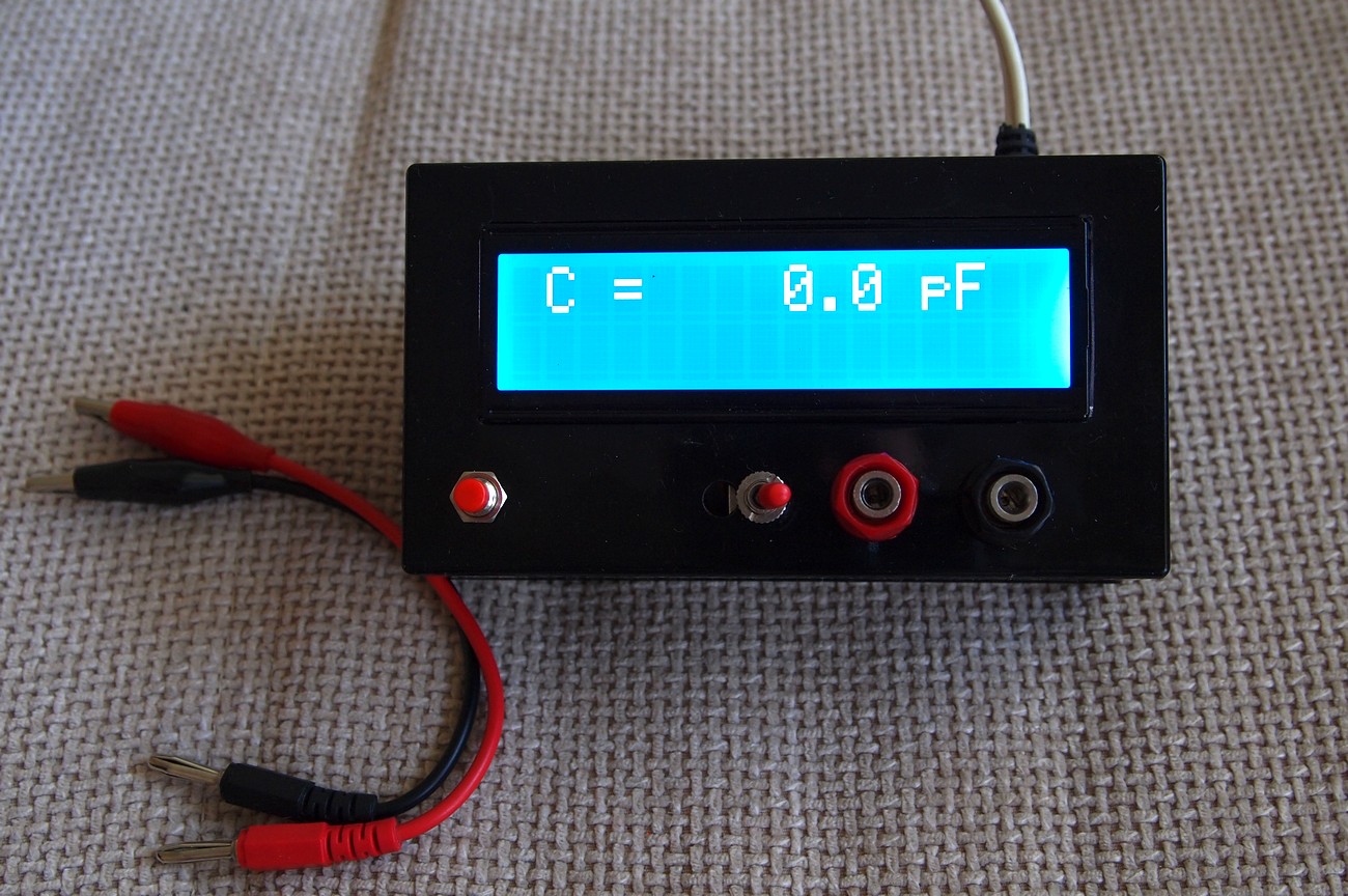
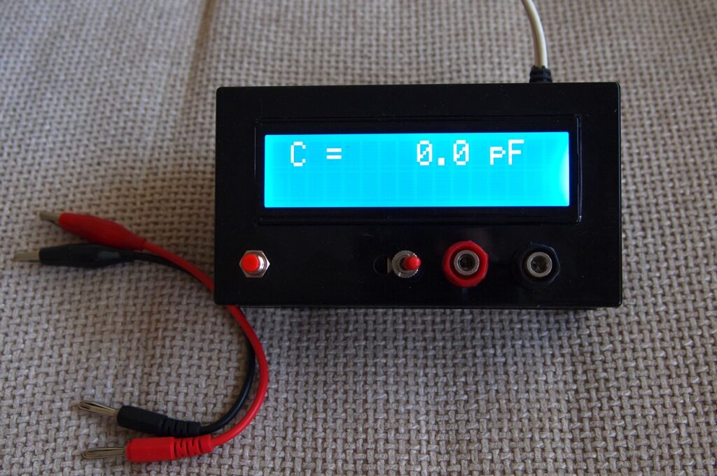
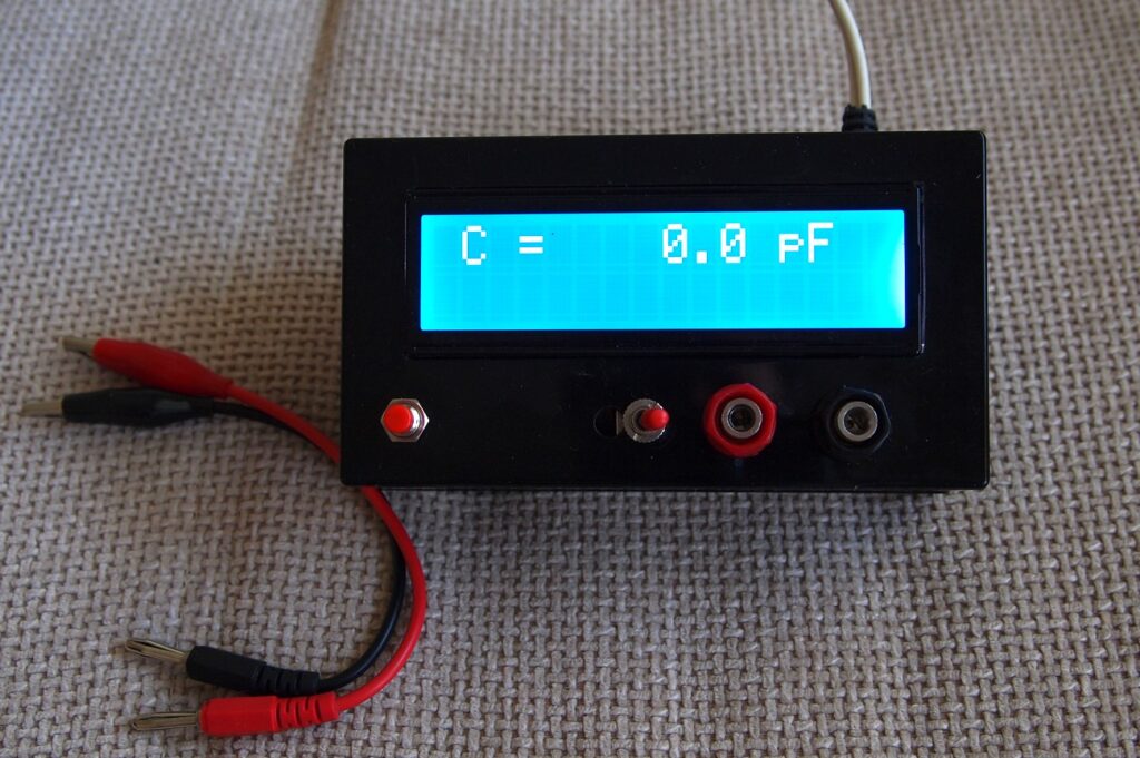
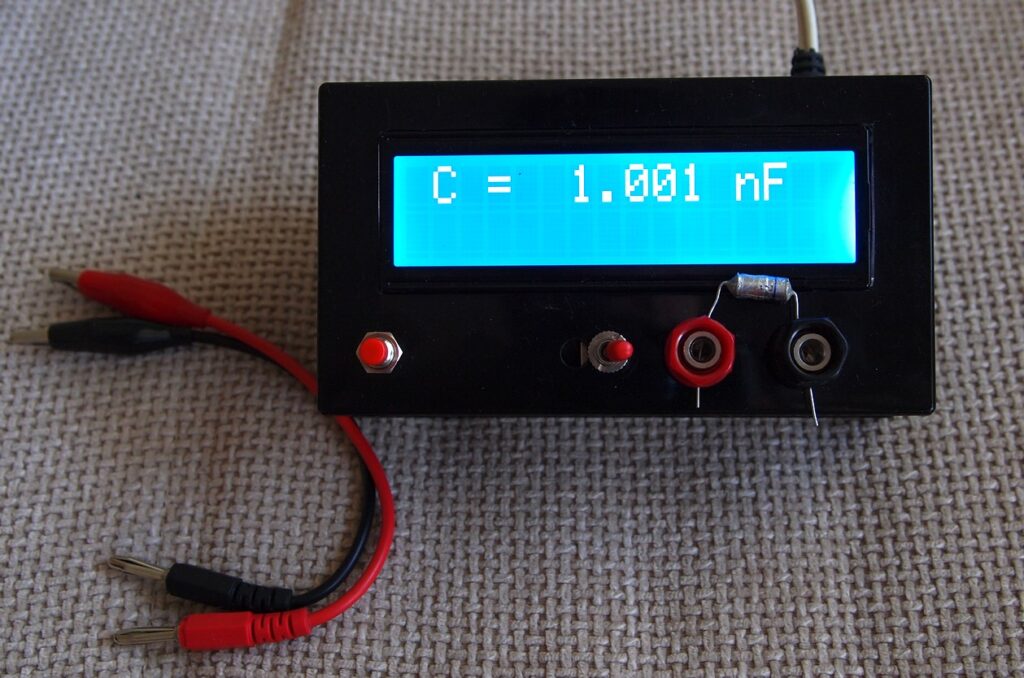
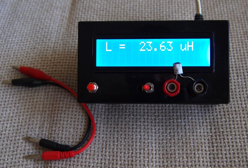
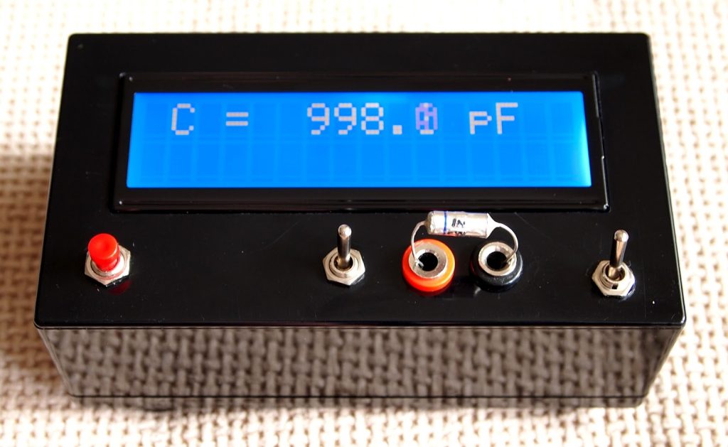
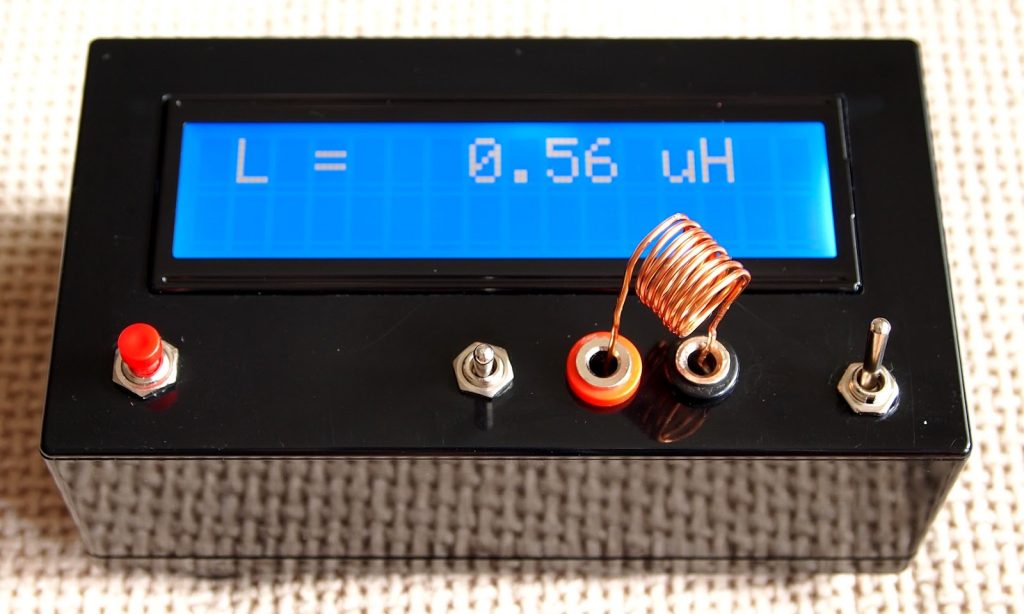
The last two pictures shows LC meter in action. In the first of them, there is 1nF/1% capacitor and in the second – 22uH/10% inductor. The device is very sensitive – when I put the test leads there is 3-5 pF reading on display, but it is eliminated with the calibrating button.

Schematic

LC_meter_schematic

Photos

LCmeter_1

LCmeter_2

LCmeter_3

LCmeter_4

LCmeter_5

LCmeter_6

LCmeter_7


Update: 24 June 2012

One of my colleagues in a Bulgarian audio forum ask me to build him a copy of the LC meter, but this time with 9V battery power supply.  I made a new PCB with little rearrangement of the old one and adding a 78L05 voltage regulator.

I also added an automatic sleep mode, schematic of which I found here:http://www.marc.org.au/marc_proj_switch.html

The goal here was to make power consumption as low as possible. With increasing the value of R11 to 1.2kOhm which control the back light current, total current of the device was decreased to 11-12mA. Without back light at all the power consumption will be decreased even further, but the visibility suffers greatly.

After some tests, the value of the C10, which defines the ON time, was chosen to be 680nF. The ON time in this case is 10-11 min.  The MOSFET Q2 may be replaced with BS170, but bear in mind that the leads are in reverse order.

ON-OFF switch is momentary non lock type.

LC_meter_with_PS

Photos

LCmeter9V_1

LCmeter9V_2

LCmeter9V_3

LCmeter9V_4

Thermocouple Type-K amplifier

PCB_photo_2


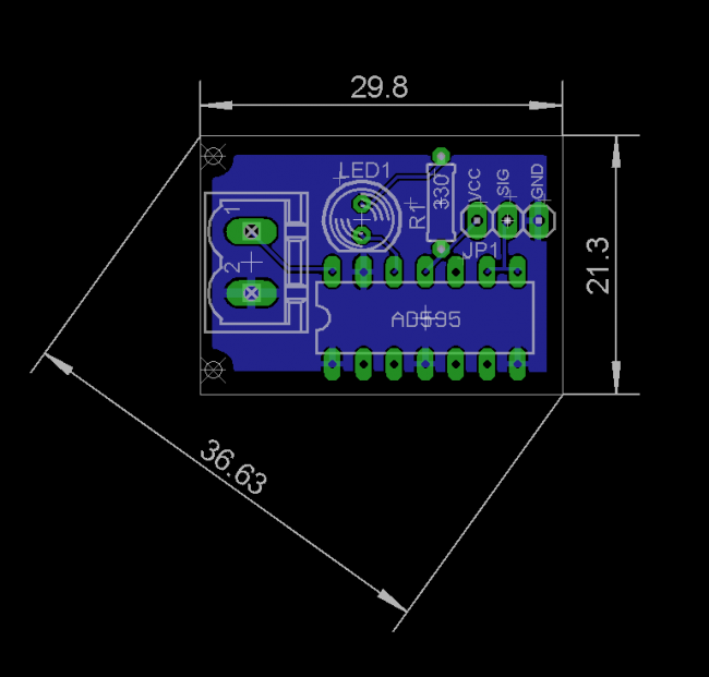
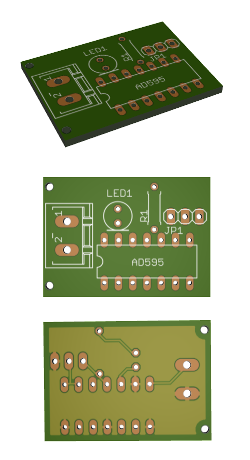
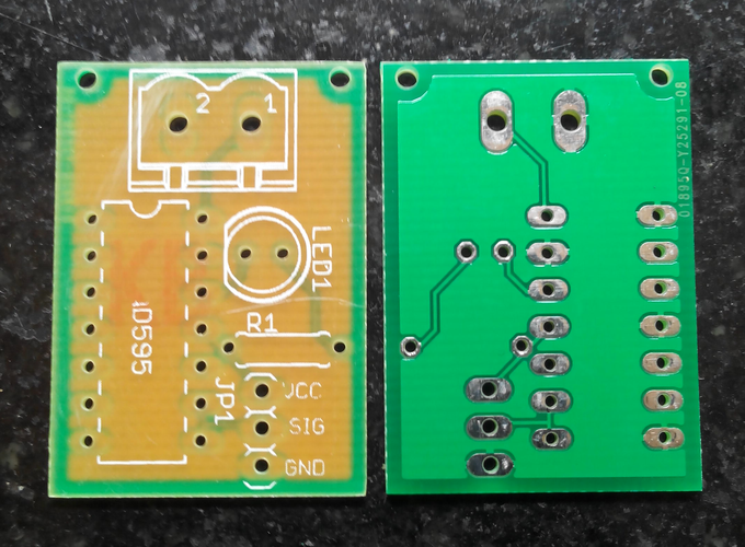
This project is a simple Thermocouple K-type amplifier based on AD595 IC. This amplifier converts the thermocouple output voltage (uV) to 10mV/C. This voltage can be easily further converted by an ADC of any microcontroller.

Description

AD595 Thermocouple Type-K Amplifier is manufactured by Analog Devices and is powered in the range of +5Vdc to +15Vdc. The output is 10mV/C and is perfect for high temperature applications. The 10mV/C analog output interfaces nicely with 10-bit ADCs found on many types of microcontrollers.

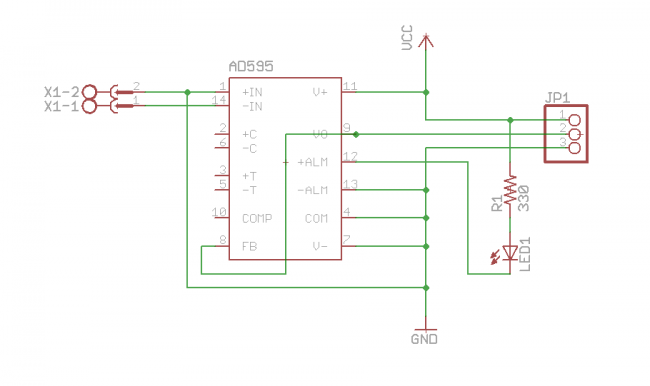
Schematic

Features

  • +/- 3C Accuracy
  • 10mV per degree C Output
  • Laser Trimmed 250mV Output at 25C
  • 5V-15V Power Supply
  • Requires only a decoupling capacitor
  • Thermocouple failure LED indicator

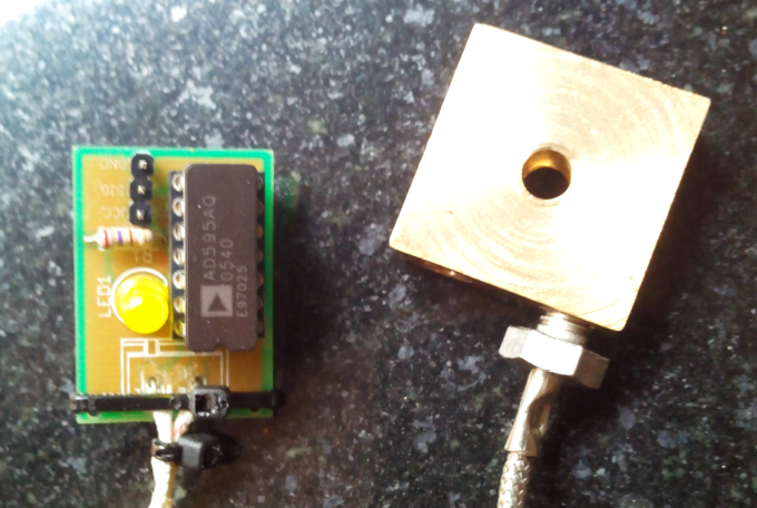
I soldered the leads directly to the board, because it lead to better accuracy, but a connector  based approach is recommended, since most thermocouples don’t have the leads marked.

One way to determine is to manually hold the leads on the solder pads and have an arduino read and show temperature. Of course, when the thermocouple is at room temperature, it read the correct temperature if leads are held in correct polarity. A reversely connected thermocouple won’t be damaged, but the board will read a lower temperature. If the thermocouple is heated (I used a soldering iron) there will be a fall in temperature if the leads are connected in reverse.

The block on the right is a brass hot end, which I am designing for a 3d printer. A thermocouple with M6 threads helps in eliminating kapton tapes and can go at much higher temperatures to melt high temperature plastics like nylon.

PCB Design

PCB_dimensions

3D_PCB

PCB_photo_1

Simple SMD LED tester

SAMSUNG


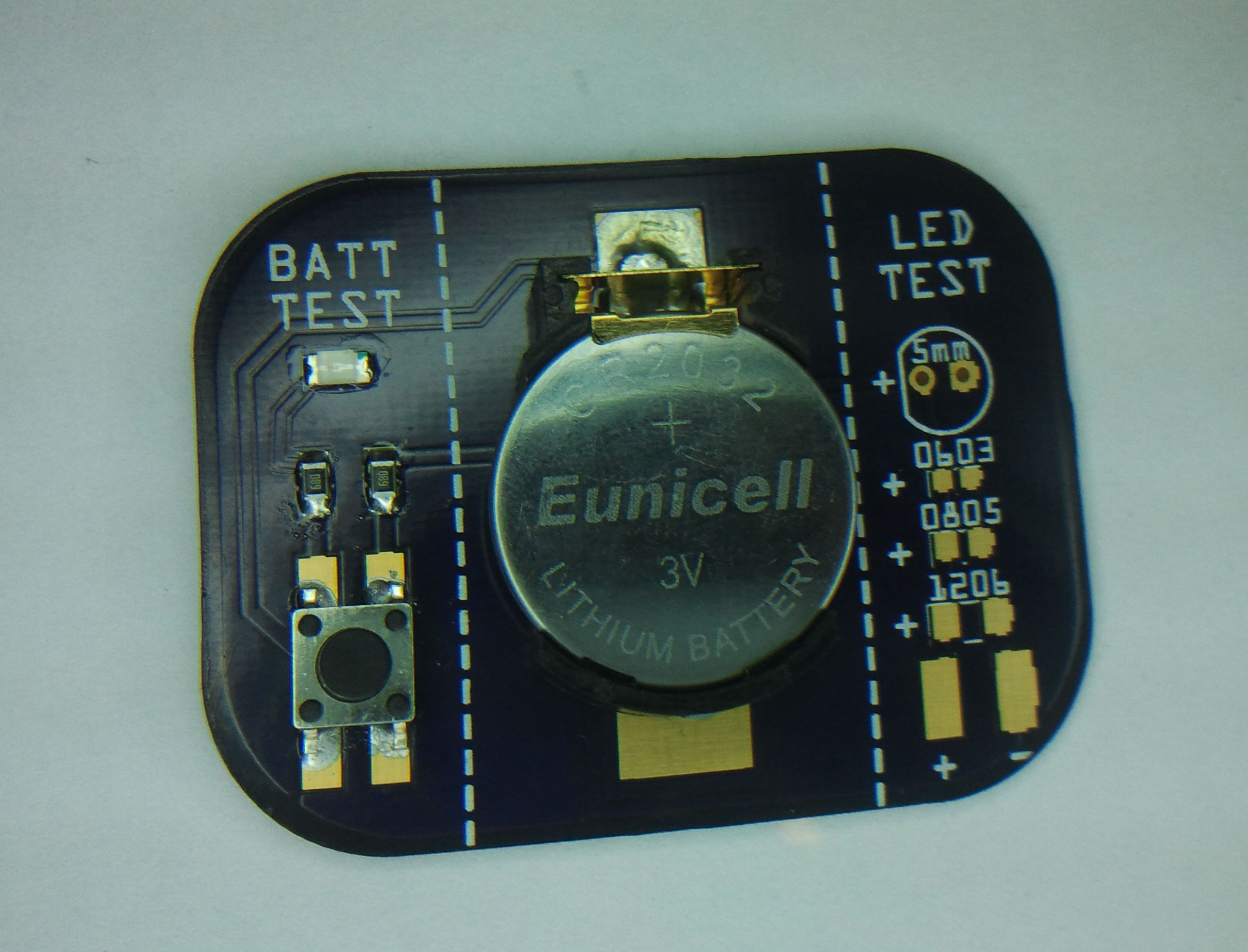
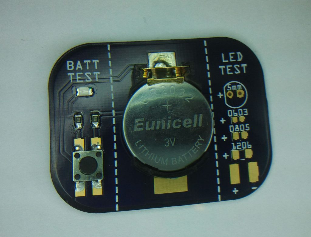
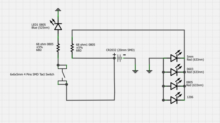
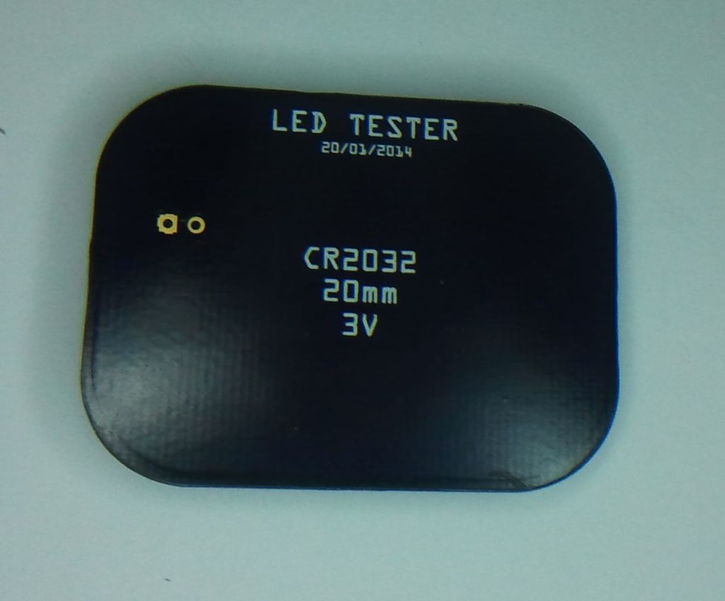
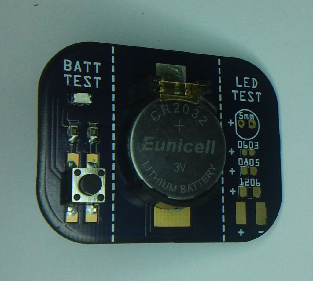
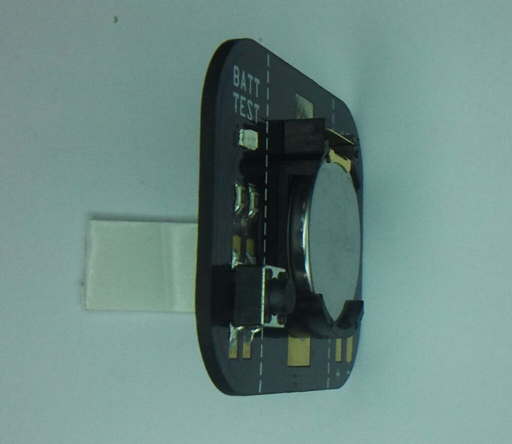
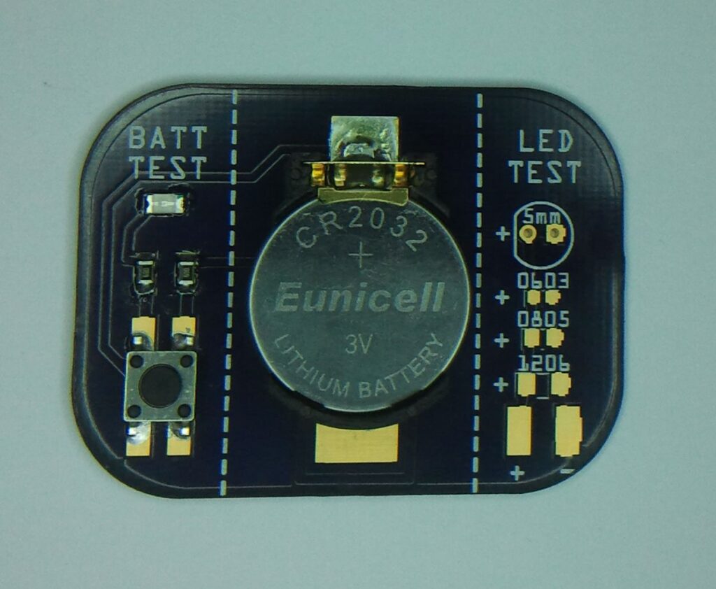
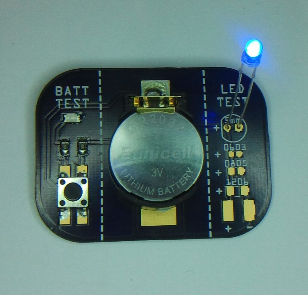
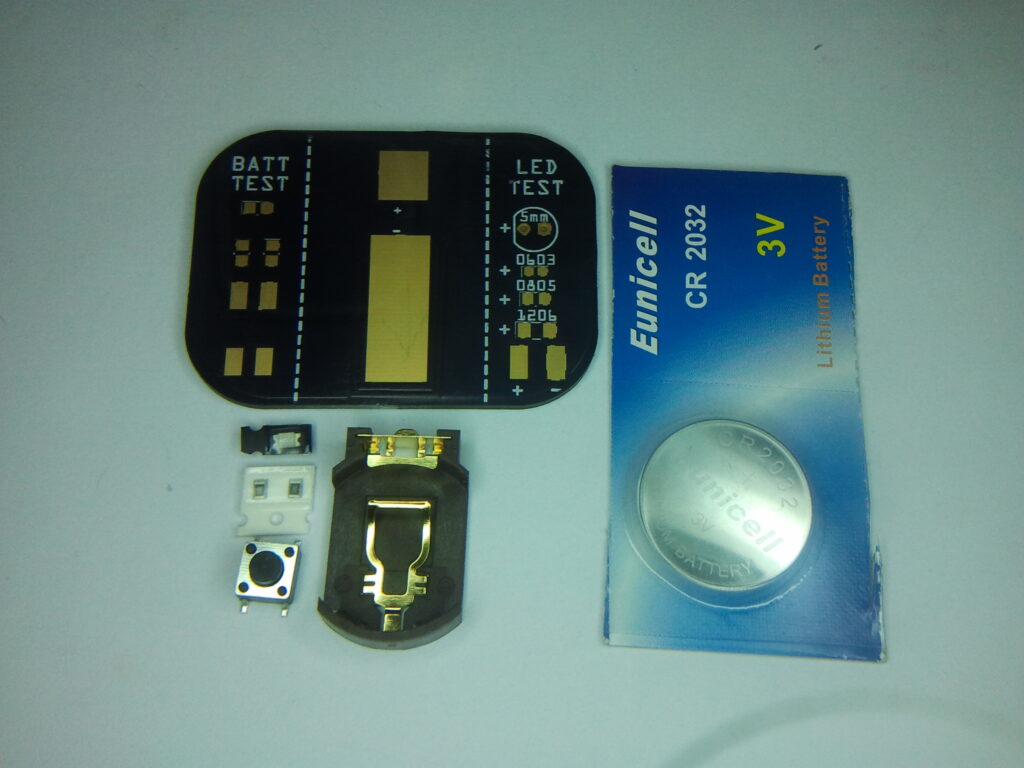
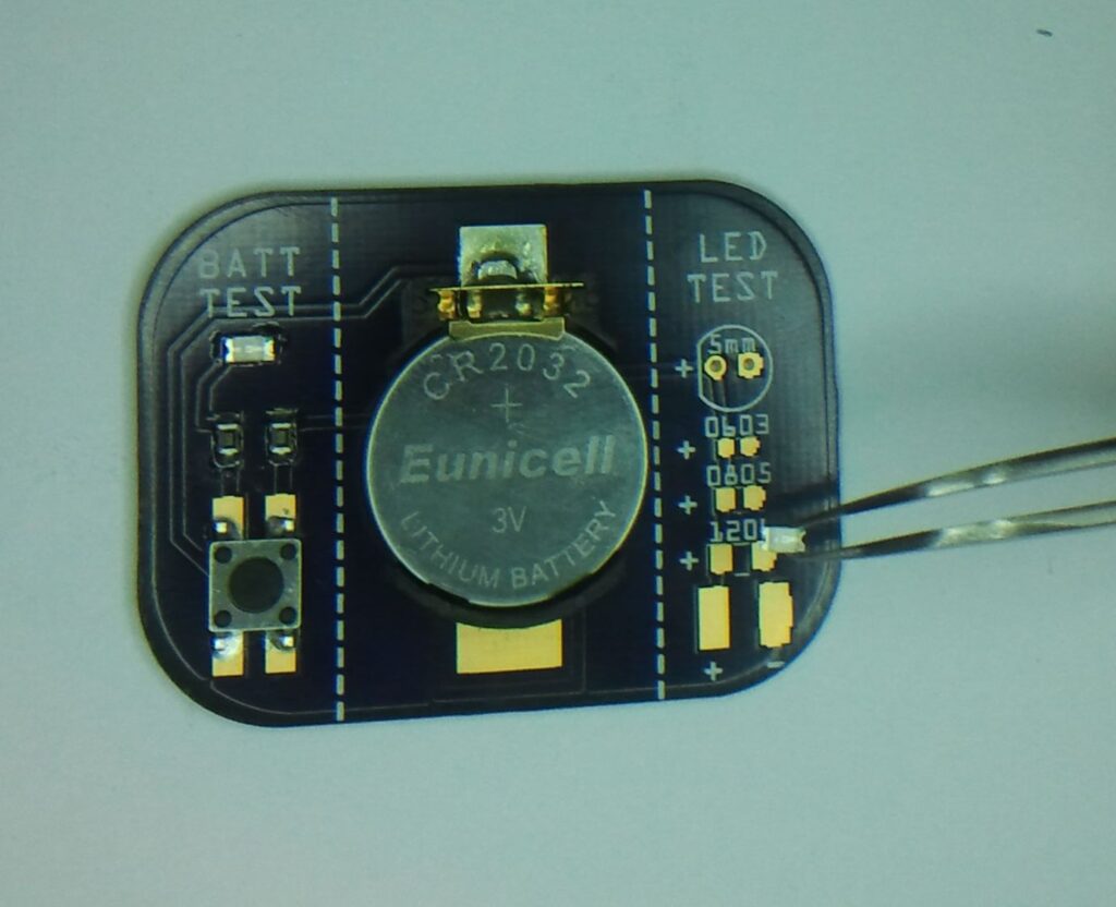
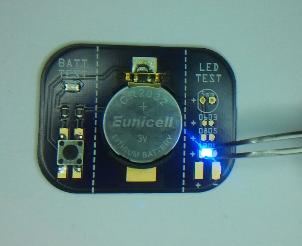
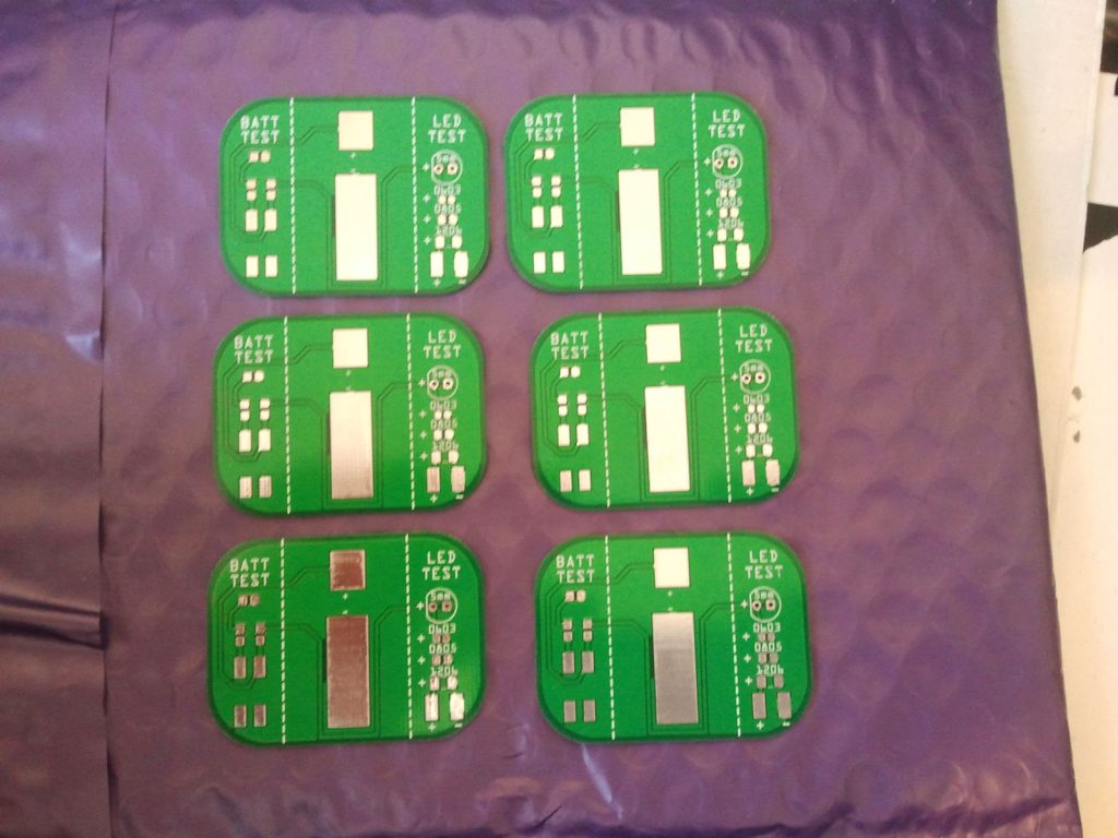
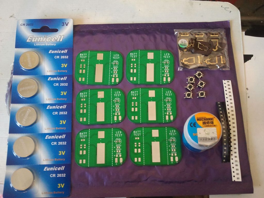
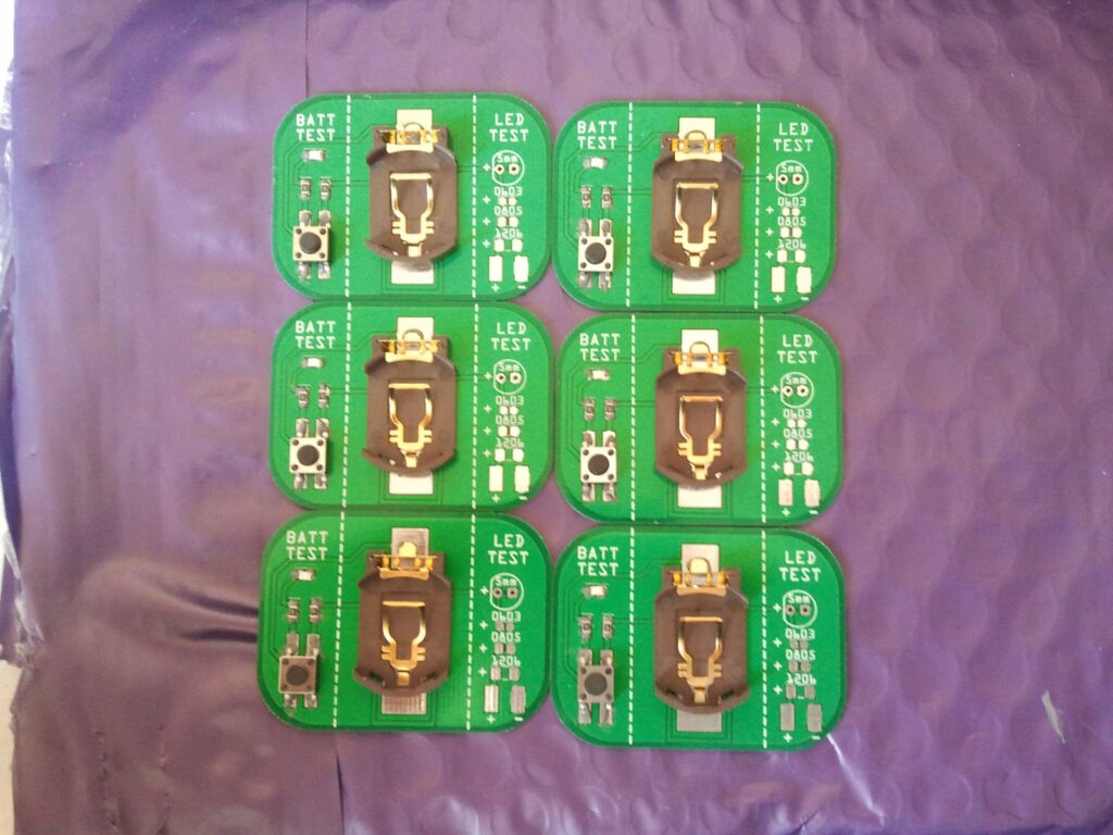
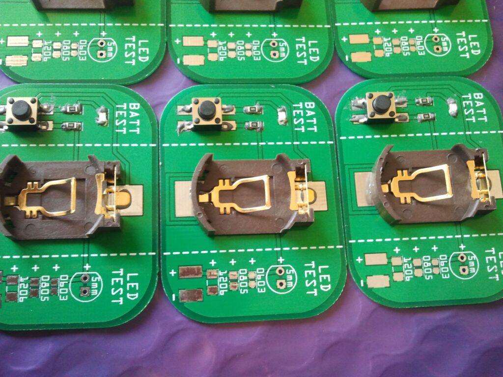
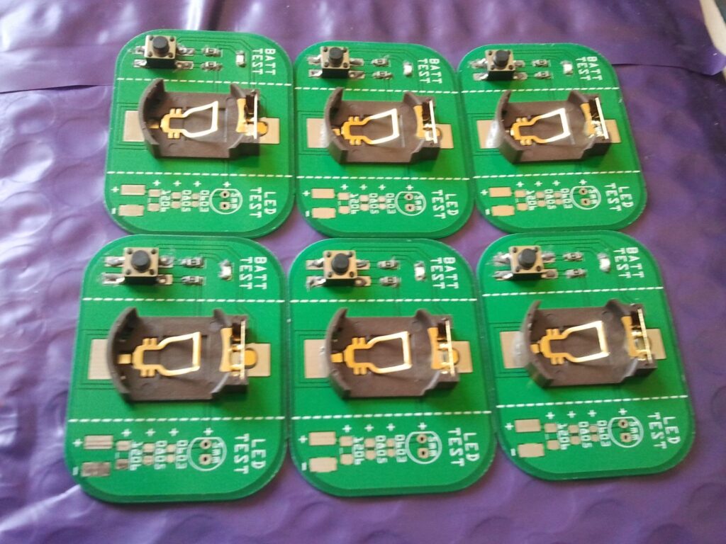
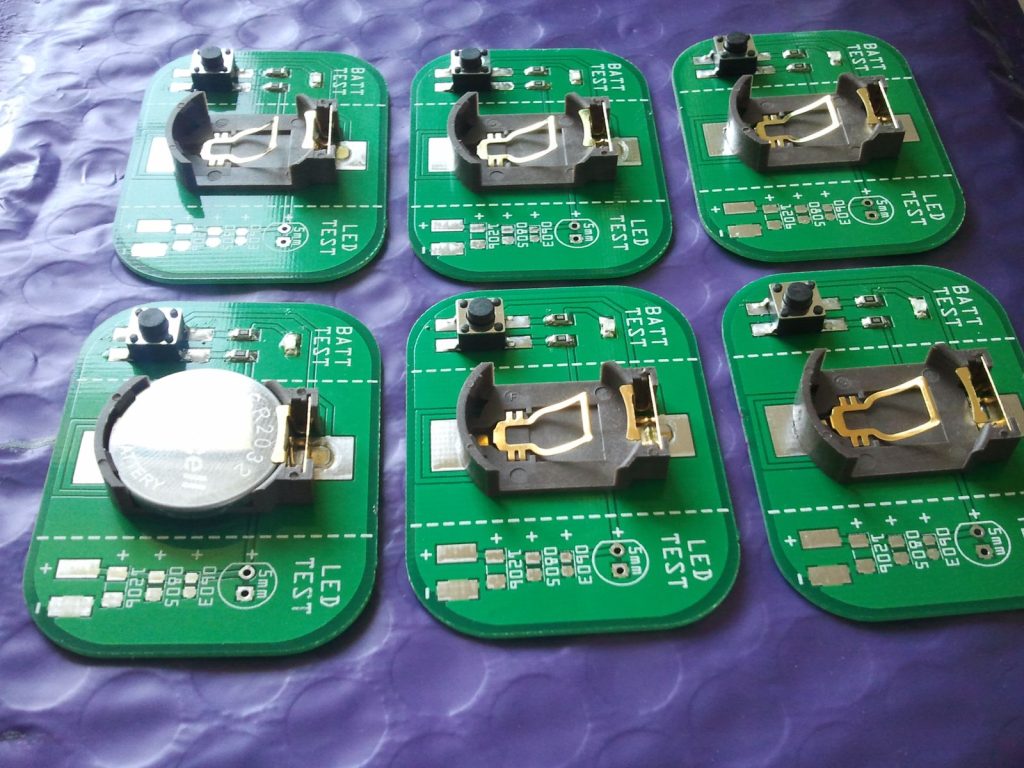
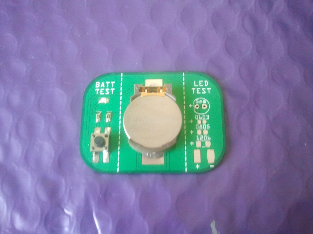
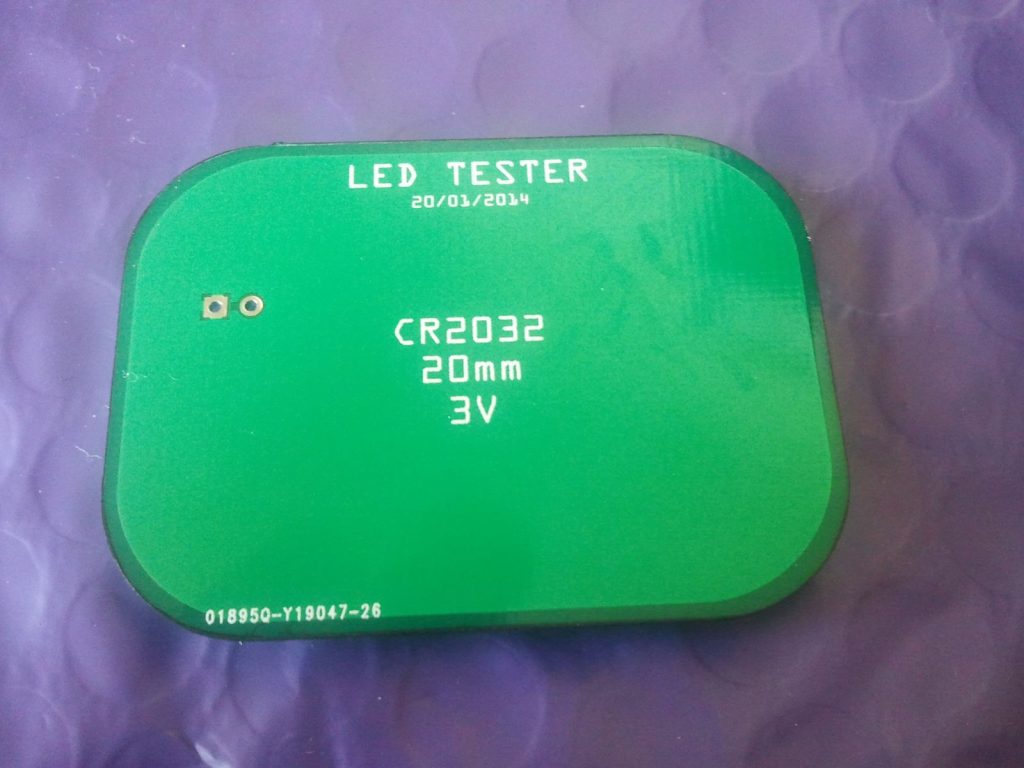
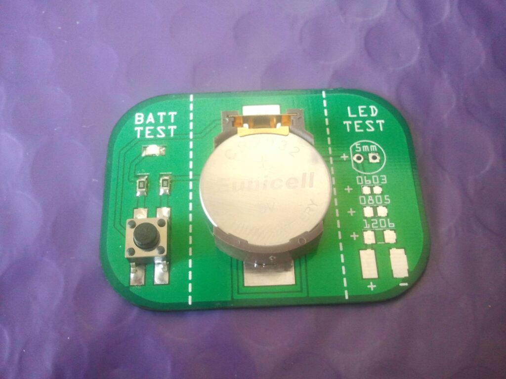
This project is a simple LED tester and LED polarity checker. It can be used to check 1206, 0805, 0603 and 5mm LEDs. All parts are readily available and they are very cheap.

Description

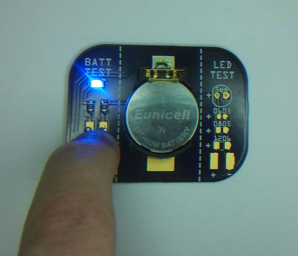
Usage is very simple. Just press the tack switch to first check the battery is good. The blue led will turn on. Now you are ready to test your leds and check their polarity.

schematic

I always use this every time I want to use leds in my designs as in the past I have used faulty leds and even found incorrectly marked polarity on leds. This reassures you each led you use is 100% working and polarity is correct. So this can save you loads of unnecessary fault checking later on.

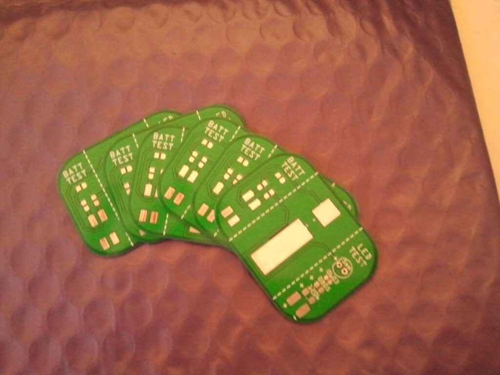
The schematic and PCB are designed using Fritzing Software and files are available an the bottom of the page.

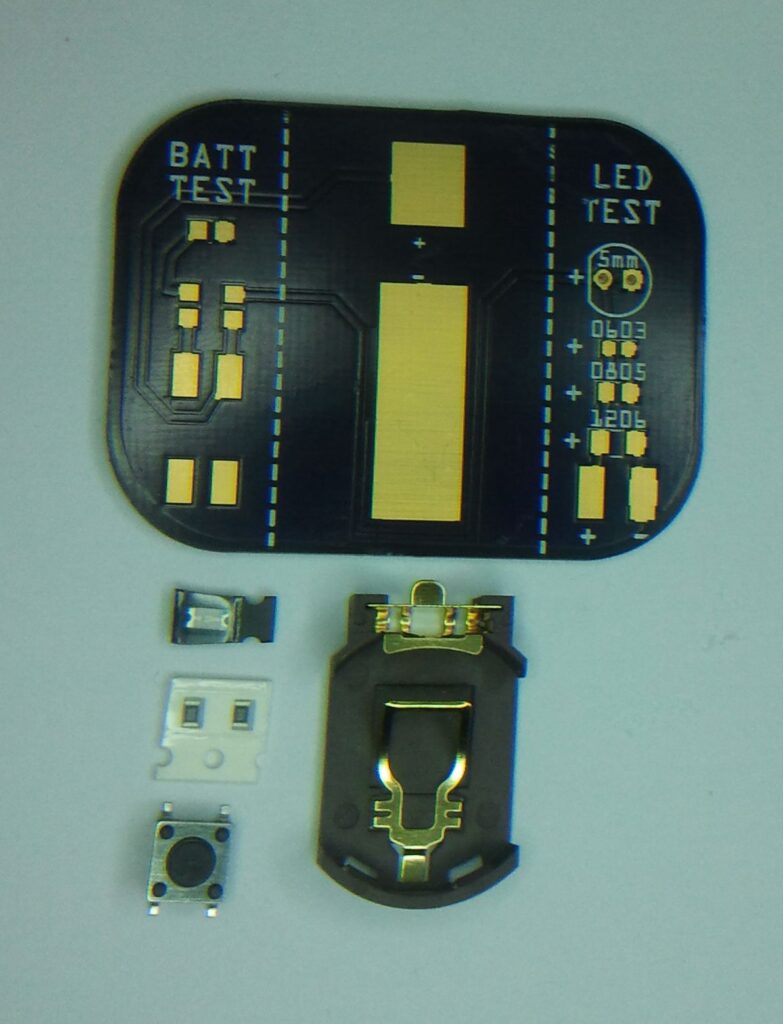
Main Parts

image_1

image_2

Photos

SAMSUNG

SAMSUNG

SAMSUNG

SAMSUNG

SAMSUNG

SAMSUNG

SAMSUNG

SAMSUNG

SAMSUNG

SAMSUNG

SAMSUNG

SAMSUNG

SAMSUNG

SAMSUNG

SAMSUNG

SAMSUNG

SAMSUNG

photo_19

SAMSUNG

SAMSUNG

SAMSUNG


Low Frequency Spectrum Analyzer for Automotive Suspension Analysis

Screenshot

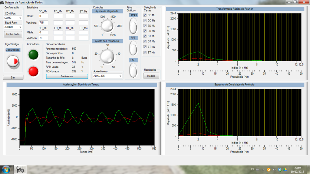
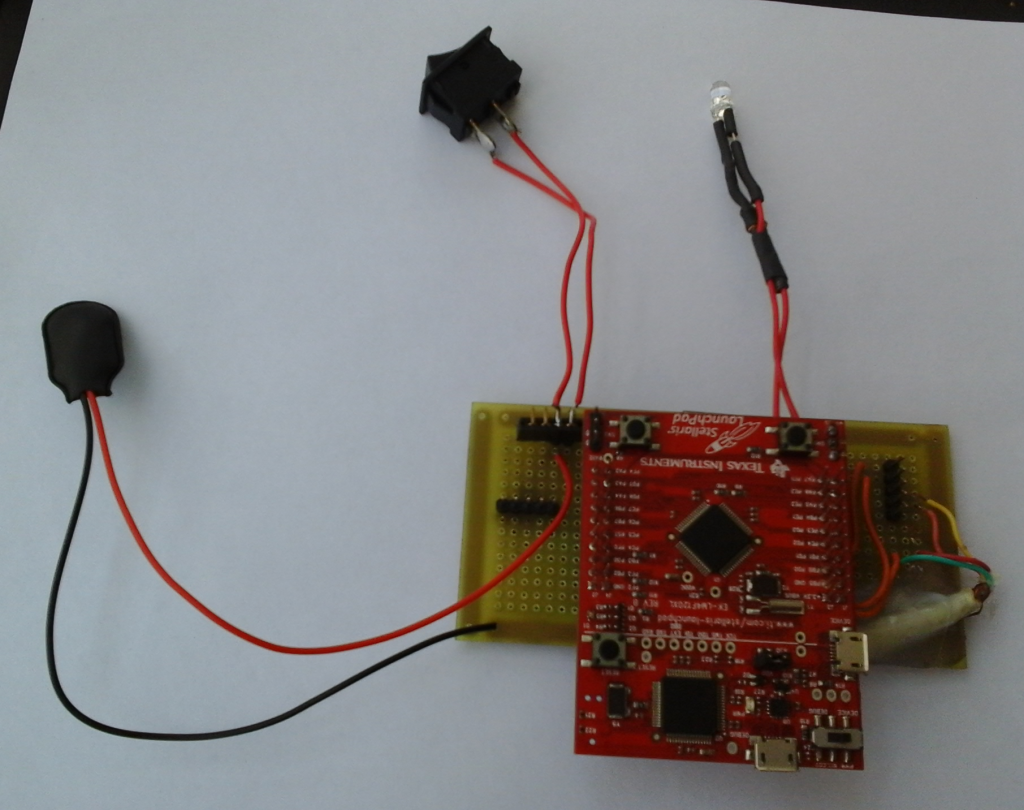
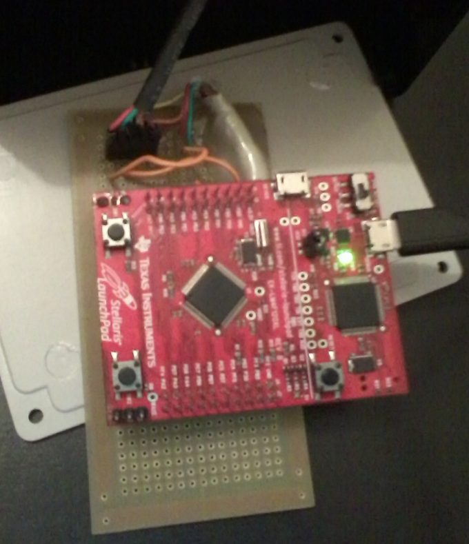
This project is an accelerometer data acquisition system for automotive suspension analysis. In other words it’s a low frequency spectrum analyzer based on Lanchpad TIVA Series from Texas Semiconductors.

Description

It’ s a spectrum analyzer for mechanical frequencies (max. 50 Hz). In my application I use this analyzer for the signals from a suspension of a car, that contain information about comfort (ride) of a vehicle.

The system is based in 3 parts:

  • the GUI (user interface),
  • the hardware (core is a LM4F120 that is an ARM of Texas Instruments) and
  • accelerometers (in my case, needed for vibration analysis).

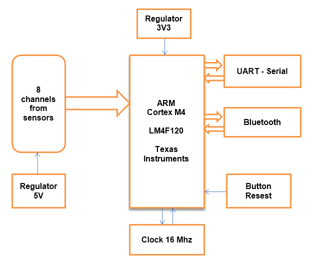
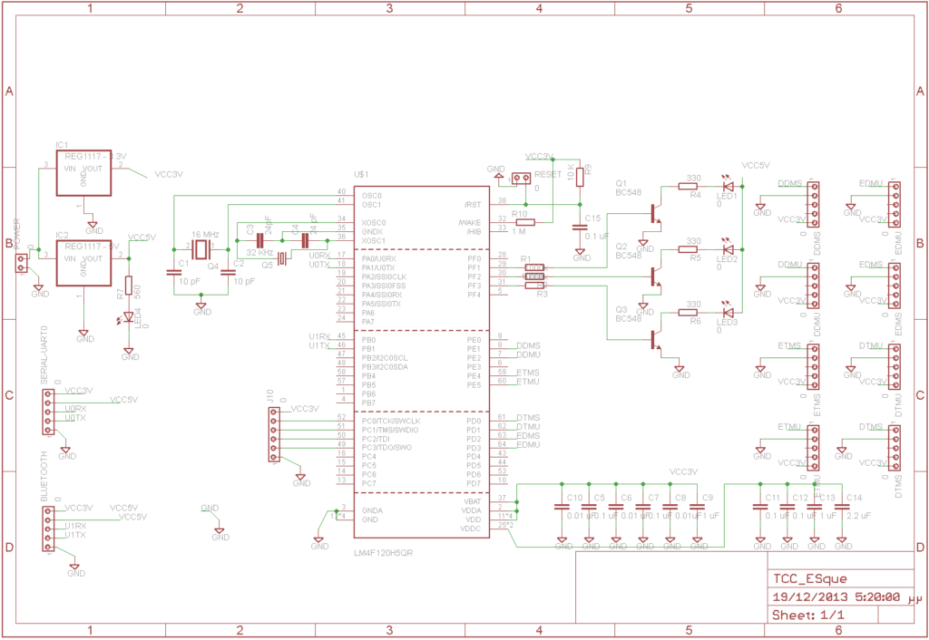
The hardware contains two voltage regulators (3.3V, 5V), 8 connectors for AD, 1 channel for serial protocol, 1 channel for Bluetooth, and one reset button. System status is displayed using three LEDs and a one LED is for 5V power supply indication.

The main component is the ARM processor. The firmware, contains a FIR low pass filter with 75 Hz cutoff frequency , sample frequency is 512 Hz, 256 points FFT and Power Density Spectrum based on Welch Method.

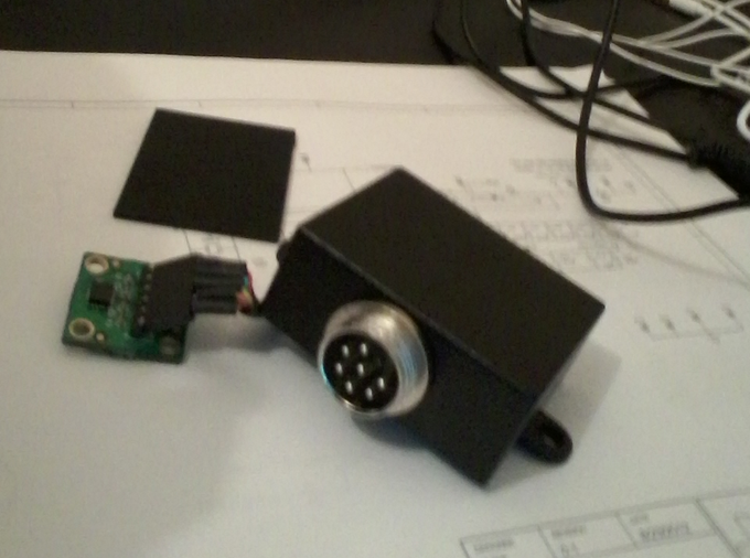
The accelerometers used are 4x ADXL 335 (+/- 3g) and 4x ADXL 325 (+/- 2g) with 3V supply voltage.

system_diagram

photo_1

LaunchPad_th

Accelerometer_th

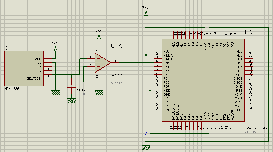
Schematic

Schematic

ADXL335

connection of ADXL335 to MCU

Photos

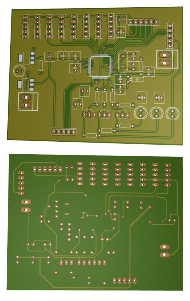
3D_PCB

3D PCB rendering

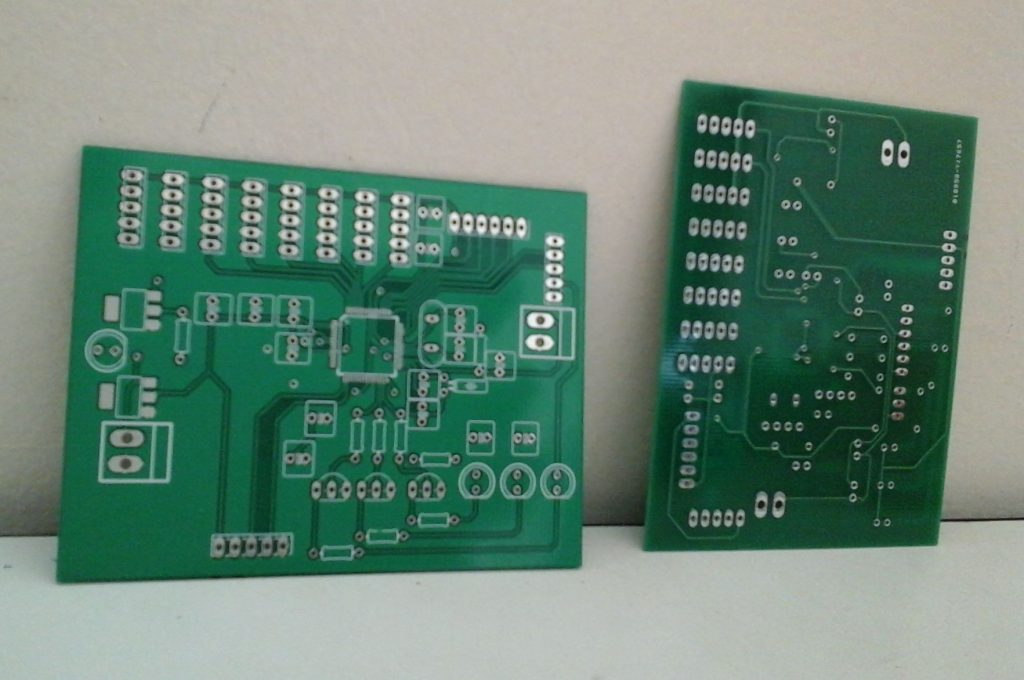
photo_2

manufactured PCB

TraId – Transistor Type & Polarity Identifier

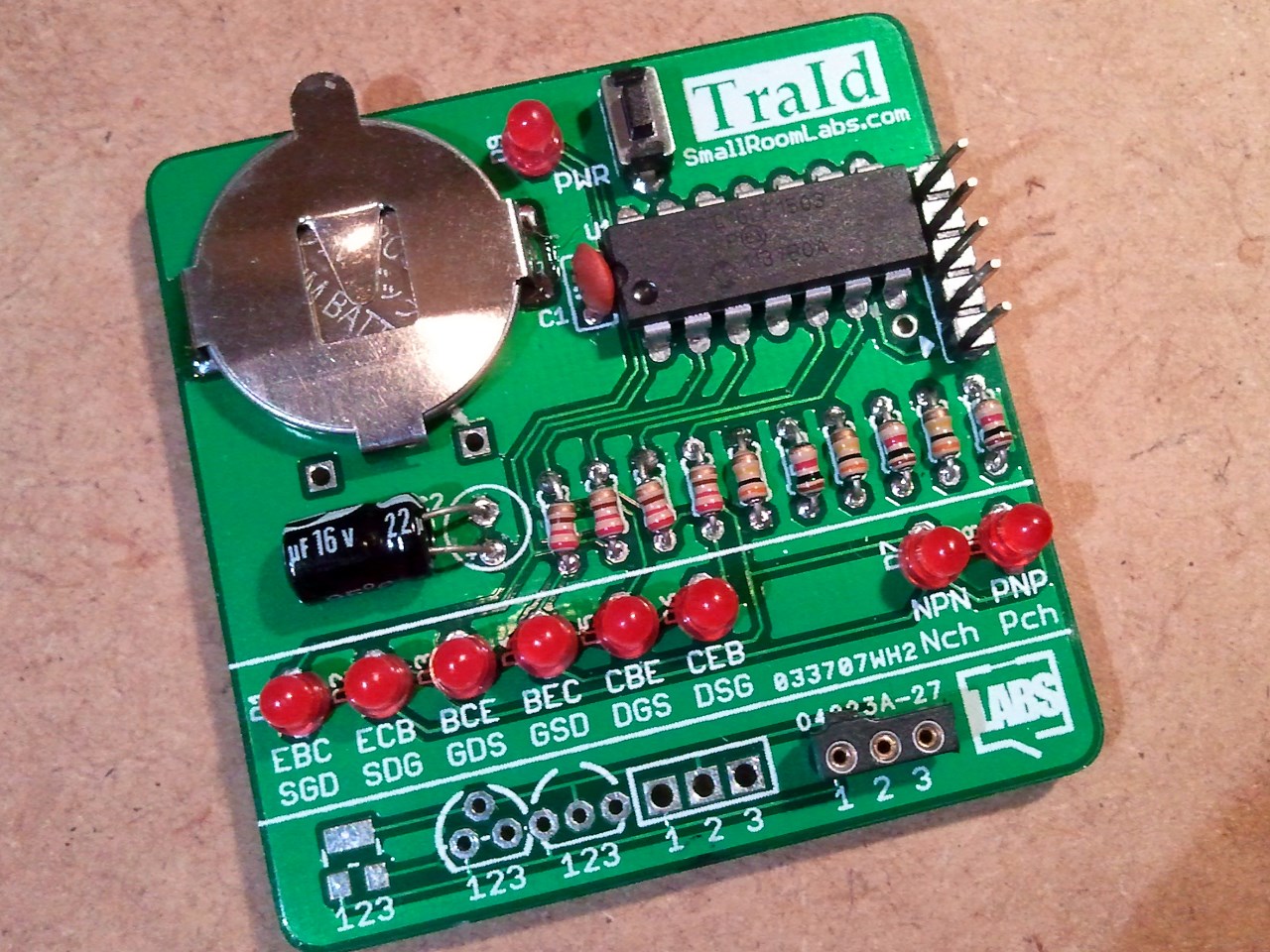
SAMSUNG


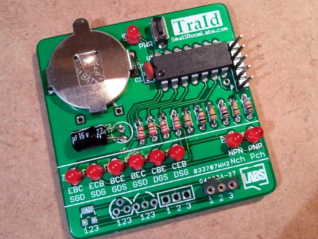
TraId is a simple transistor tester and pinout identifier. It is able to test bipolar transistors as well as N-mosfet and P-mosfet. Result are displayed using LEDs driven by a PIC16LF1503 microcontroller.

Description

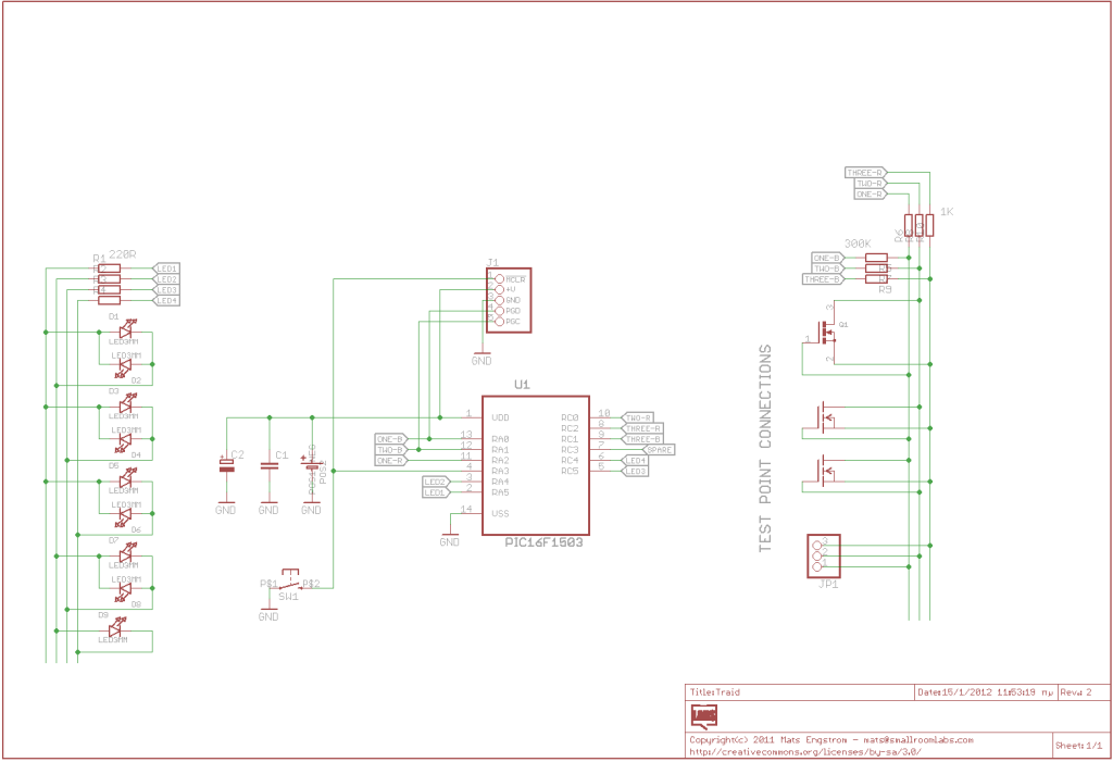
The board is using a 14 pin PIC16LF1503 (less than a dollar in singles) and runs on a single CR2032 battery. I’m using a 1K and a 300K resistor connected to each of the three transistor pins, putting out either 0 or 3 volts via the resistors and analyzing the resulting voltages using the PIC ADC.

The firmware, written in C, uses 1.3K of the available 2K so there’s room for some more additions and improvements down the road.

There’s no power switch on the board, the PIC simply goes into deep sleep after a while and is awakened by a press on the reset button.

The pic have a spare pin connected to the via below pin 7. I have it connected to a 2×8 LCD with a 1-wire serial “roman black” backback as described in this thread.

Schematic

schematic

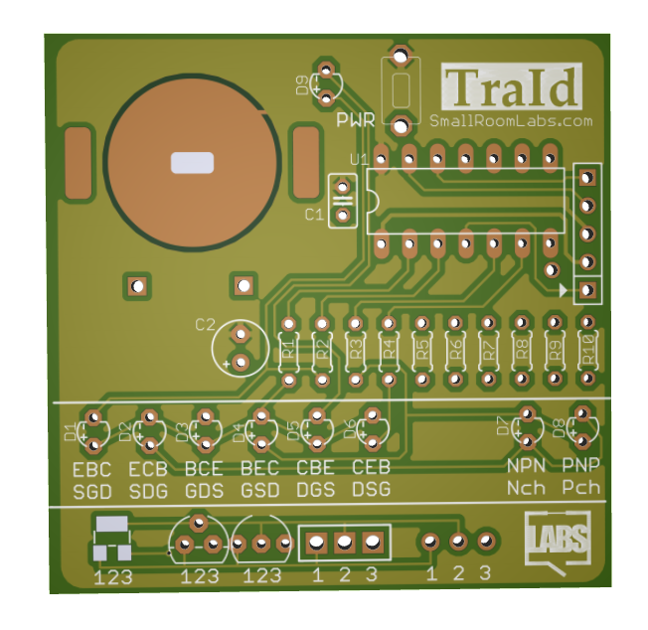
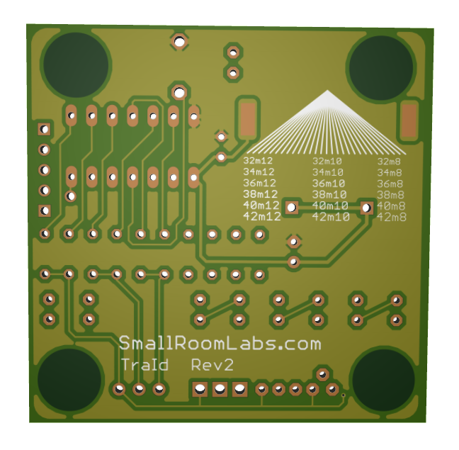
PCB

3D_PCB_top

3D_PCB_bottom


PIC16F688 Digital Voltmeter

Photo_1

Introduction

This project describes how to make a digital voltmeter using a PIC microcontroller. A HD44780 based character LCD is used to display the measured voltage. The PIC microcontroller used in this project is PIC16F688 that has 12 I/O pins out of which 8 can serve as analog input channels for the in-built 10-bit ADC. The voltage to be measured is fed to one of the 8 analog channels. The reference voltage for AD conversion is chosen to be the supply voltage Vdd (+5 V). A resistor divider network is used at the input end to map the range of input voltage to the ADC input voltage range (0-5 V). The technique is demonstrated for input voltage ranging from 0-20 V, but it can be extended further with proper selection of resistors and doing the math described below.

Circuit Diagram

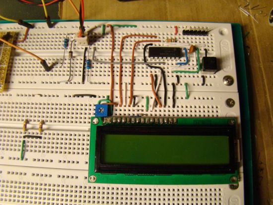
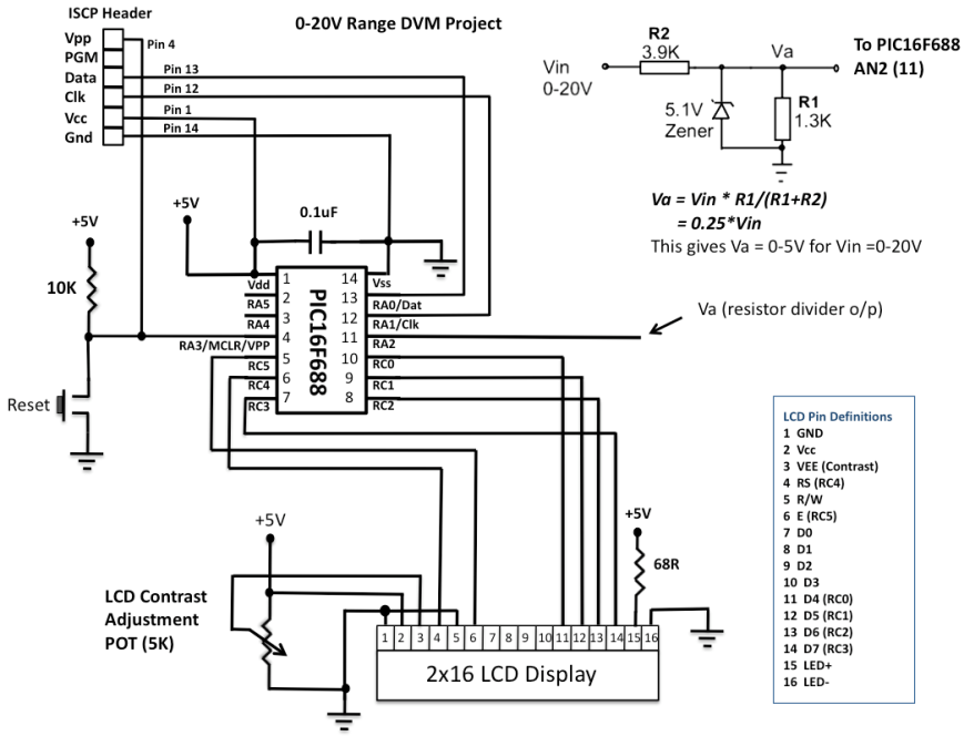
Since the PIC port cannot take 20V input directly, the input voltage is scaled down using a simple resistor divider network. The resistors R1 and R2 scale down the input voltage ranging from 0-20V to 0-5V, before it is applied to PIC16F688’s analog input channel, AN2. A 5.1V zener diode connected in parallel between the port pin AN2 and the ground provides protection to the PIC pin in case the input voltage accidentally goes beyond 20V. The LCD display is connected in 4-bit mode, and the ICSP header makes the firmware development easier as you can reprogram and test the PIC while it is in circuit. When you are satisfied and want to transfer the circuit from the breadboard to a PCB or general-purpose prototyping board, you don’t need the ICSP header. The circuit diagram and the prototype built on a breadboard are shown below.

Schematic

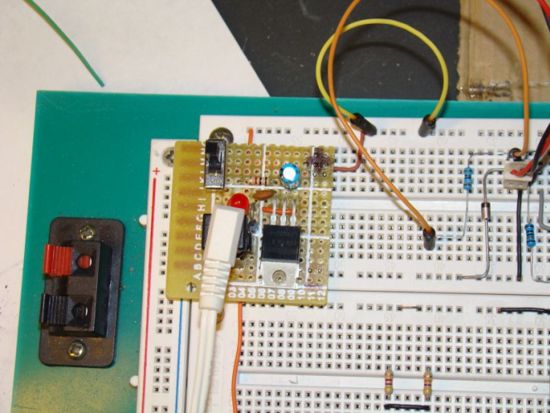
Important: You need a regulated +5V supply for accuracy of the output. The ADC uses Vdd as the reference for conversion, and all computations are done with Vdd = 5V. You can get a regulated +5V using a LM7805 linear regulator IC.

Photo_2

Getting a regulated +5V from a LM7805 IC

Photo_3

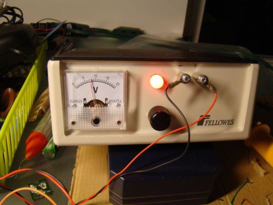
Variable power supply source for testing the DVM

ADC Math

The accuracy depends upon the accuracy of the resistors at the input end and the stability of reference voltage, Vdd = +5V. I found Vdd is stable to +5.02 V.  I measured R1 and R2, and their values are 1267 and 3890 Ohms. So this gives:

0 – 5.02 V Analog I/P —> 0-1023 Digital Count=> Resolution = (5.02 – 0)/(1023-0) = 0.004907 V/CountVa = 1267*Vin/(1267+3890) = 0.2457*Vin=> I/P voltage = 4.07*Va = 4.07* Digital Count * 0.004907 = 0.01997 * Digital Count = 0.02*Digital Count (Approx.)
 
To avoid floating point, use I/P voltage = 2*Digital Count.
 
Example, suppose Vin = 7.6V. Then,
Va = 0.2457*Vin = 1.87V=> Digital Count = 1.87/0.004907 = 381=> Calculated I/P Voltage = 2*381 = 0762 = 07.6V  (First 3 digits of 4 digit product)

Firmware

The firmware is written and compiled with mikroC compiler. The code is here.
 
/*
  Digital Voltmeter based on PIC16F688
  Rajendra Bhatt, Oct 12, 2010
*/
 
// LCD module connections
sbit LCD_RS at RC4_bit;
sbit LCD_EN at RC5_bit;
sbit LCD_D4 at RC0_bit;
sbit LCD_D5 at RC1_bit;
sbit LCD_D6 at RC2_bit;
sbit LCD_D7 at RC3_bit;
sbit LCD_RS_Direction at TRISC4_bit;
sbit LCD_EN_Direction at TRISC5_bit;
sbit LCD_D4_Direction at TRISC0_bit;
sbit LCD_D5_Direction at TRISC1_bit;
sbit LCD_D6_Direction at TRISC2_bit;
sbit LCD_D7_Direction at TRISC3_bit;
// End LCD module connections
 
char Message1[] = "DVM Project";
unsigned int ADC_Value, DisplayVolt;
char *volt = "00.0";
 
void main() {
  ANSEL = 0b00000100; // RA2/AN2 is analog input
  ADCON0 = 0b00001000; // Analog channel select @ AN2
  ADCON1 = 0x00;
  CMCON0 = 0x07 ; // Disbale comparators
  TRISC = 0b00000000; // PORTC All Outputs
  TRISA = 0b00001100; // PORTA All Outputs, Except RA3 and RA2
  Lcd_Init();        // Initialize LCD
  Lcd_Cmd(_LCD_CLEAR);             // CLEAR display
  Lcd_Cmd(_LCD_CURSOR_OFF);        // Cursor off
  Lcd_Out(1,1,Message1);
  Lcd_Chr(2,10,'V');
 
do {
 
   ADC_Value = ADC_Read(2);
   DisplayVolt = ADC_Value * 2;
   volt[0] = DisplayVolt/1000 + 48;
   volt[1] = (DisplayVolt/100)%10 + 48;
   volt[3] = (DisplayVolt/10)%10 + 48;
   Lcd_Out(2,5,volt);
   delay_ms(100);
  } while(1);
 
 }


Output

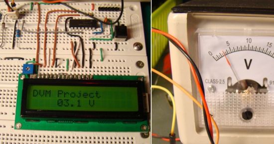
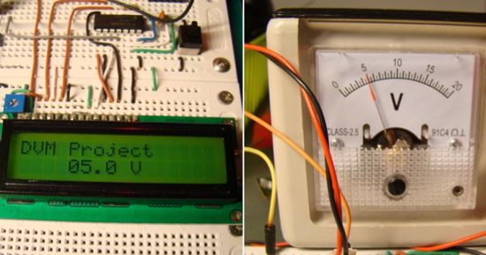
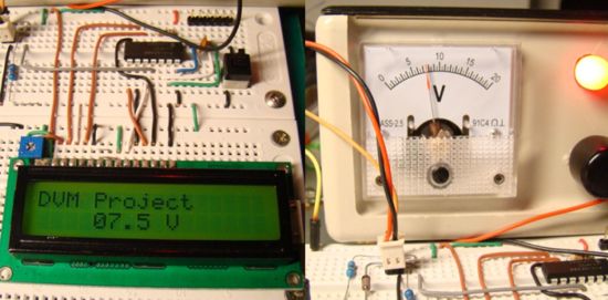
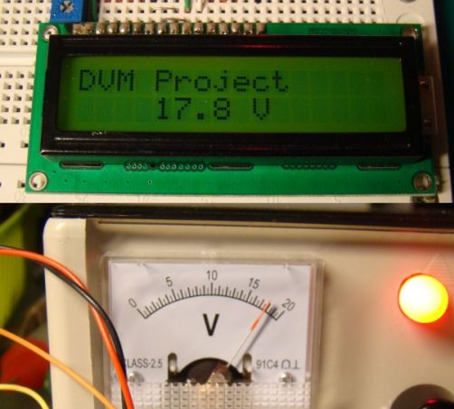
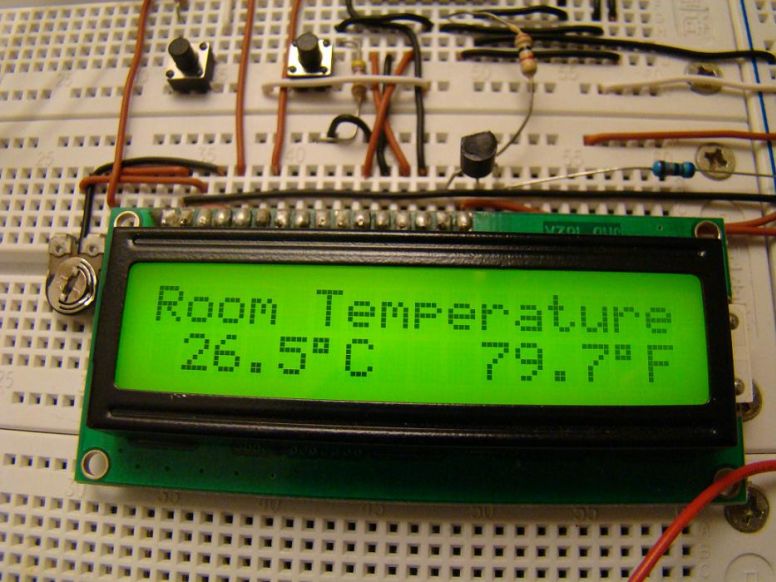
The DVM is tested for various input voltages ranging from 0-20 V and found to be very accurate. Some snapshots of the testing are here.

Photo_4

Photo_5

Photo_6

Photo_7 (1)


Digital Room Thermometer

photo_1

Introduction

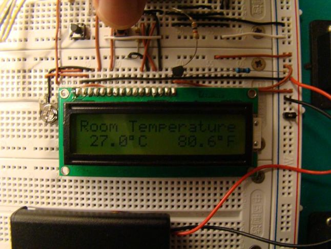
Room temperature plays a vital role in determining human thermal comfort. This digital thermometer is designed to measure room temperature and display it on a LCD screen in both Celsius and Fahrenheit scales. A PIC16F688 microchip is used as the main controller that reads temperature from DS1820, a 3-pin digital temperature sensor from Dallas semiconductors (now Maxim). The sensor is designed to measure temperature ranging from -55 to +125 °C in 0.5 °C increments.

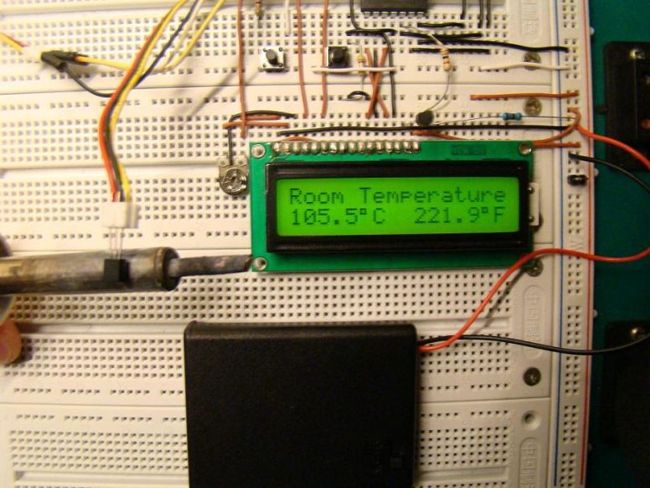
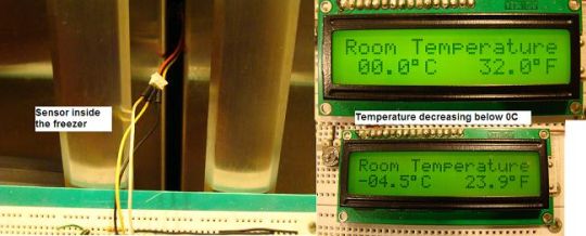
The room temperature doesn’t go that far but the firmware written for the PIC is able to read and display the entire temperature range of DS1820. I have tested it from -4.5°C (my freezer temperature) to 105.5 °C (by bringing a soldering iron tip close to the sensor). If you want to measure your freezer temperature too, don’t put the entire unit inside it, as some of the components (like LCD) may not work at that low temperatures. Rather put only the sensor inside the freeze and connect it to the rest of the system through three wires.

About DS1820

For a better understanding of how DS1820 sensor works, I recommend to read the datasheet from Maxim website. Remember that DS1820 and DS18B20 (both are temperature sensors) have architectural differences, and so DS18B20 will not work here. This project works with DS1820, and it would work with DS18S20 (later version of DS1820) too by changing the temperature conversion time in the firmware. Read this to find the difference between DS1820 and DS18S20, http://www.maxim-ic.com/datasheet/index.mvp/id/3021

The temperature reading from DS1820 is 9-bits which are read by PIC16F688 in two bytes (TempH and TempL), and then are combined into one 2-byte integer. In order to avoid floating point math during C to F conversion, the temperature value is first multiplied by 10. For example, 24.5 C becomes 245. Now C to F conversion is fairly easy.

TempinF = 9*TempinC/5 + 320 = 761 (which is 76.1 F)

The negative temperatures are read in 2’s complement form, so if the most significant bit of the 2-byte temperature reading from DS1820 is 1, it means the temperature is below 0°C. The firmware takes care of all negative temperature readings (in both C and F scales). The computed temperature is displayed on LCD as a 5 digit string array, xxx.x (e.g., 24.5, 101.0, -12.5, etc).

Circuit Diagram

PIC16F688 reads data from DS1820 sensor through RA5 port, and the computed temperature is sent to the LCD through RC0-RC3 ports. It means the data transfer from PIC to LCD is achieved in 4-bit mode. The Register Select (RS) and Enable (E) signals for LCD are provided through ports RC4 and RC5. The Read/Write pin of the LCD is grounded as there is no data read from the LCD in this project. The contrast adjustment of LCD is done with the 10K potentiometer shown in the circuit diagram.
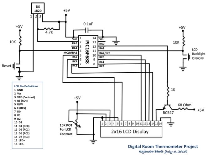
Schematic


There are two tact switches for user inputs. The first one is the reset switch which, when pressed, will reset the whole system and reinitialize the LCD. The another tact switch connected to the external interrupt pin of PIC16F688 is for turning the LCD back light ON and OFF. In low illumination condition, the in-built LCD back light can be toggled by pressing this switch. An interrupt service routine is written for back light toggling. When the system is first turned ON, the LCD back light will turn ON too.
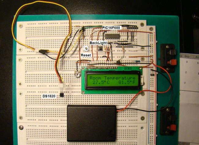
photo_2


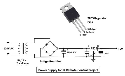
The following circuit can be used to get +5V regulated power supply required for the circuit.
Power_Supply

Firmware

The firmware was developed on mikroC compiler. The in-built libraries for DS1820 makes the firmware development easier. The code is provided with adequate comments so that the reader won’t have much difficulty in understanding programming logic. The PIC microcontroller uses internal oscillator at 4.0 MHz. In the Edit Project window of mikroC, select internal clock, MCLR enabled, WDT Disabled, and Power On Timer Enabled.

/*
  Digital Room Thermometer using PIC16F688
  Copyright@Rajendra Bhatt
  July 13, 2010
*/
 // LCD module connections
sbit LCD_RS at RC4_bit;
sbit LCD_EN at RC5_bit;
sbit LCD_D4 at RC0_bit;
sbit LCD_D5 at RC1_bit;
sbit LCD_D6 at RC2_bit;
sbit LCD_D7 at RC3_bit;
sbit LCD_RS_Direction at TRISC4_bit;
sbit LCD_EN_Direction at TRISC5_bit;
sbit LCD_D4_Direction at TRISC0_bit;
sbit LCD_D5_Direction at TRISC1_bit;
sbit LCD_D6_Direction at TRISC2_bit;
sbit LCD_D7_Direction at TRISC3_bit;
// End LCD module connections
 
// Back Light Switch connected to RA1
sbit BackLight at RA1_bit;
// Define Messages
char message0[] = "LCD Initialized";
char message1[] = "Room Temperature";
 
// String array to store temperature value to display
char *tempC = "000.0";
char *tempF = "000.0";
 
// Variables to store temperature register values
unsigned int temp_whole, temp_fraction, temp_value;
signed int tempinF, tempinC;
unsigned short C_Neg=0, F_Neg=0, TempH, TempL;
 
void Display_Temperature() {
  // convert Temp to characters
 if (!C_Neg) {
     if (tempinC/1000)
   // 48 is the decimal character code value for displaying 0 on LCD
     tempC[0] = tempinC/1000  + 48;
     else tempC[0] = ' ';
  }
  tempC[1] = (tempinC/100)%10 + 48;             // Extract tens digit
  tempC[2] =  (tempinC/10)%10 + 48;             // Extract ones digit
 
  // convert temp_fraction to characters
  tempC[4] =  tempinC%10  + 48;         // Extract tens digit
 
  // print temperature on LCD
  Lcd_Out(2, 1, tempC);
 
  if (!F_Neg) {
     if (tempinF/1000)
      tempF[0] = tempinF/1000  + 48;
     else tempF[0] = ' ';
  }
 
  tempF[1] = (tempinF/100)%10 + 48;             // Extract tens digit
  tempF[2] =  (tempinF/10)%10 + 48;
  tempF[4] =  tempinF%10  + 48;
  // print temperature on LCD
  Lcd_Out(2, 10, tempF);
}
 
// ISR for LCD Backlight
void interrupt(void){
  if (INTCON.INTF == 1)          // Check if INTF flag is set
     {
     BackLight =~BackLight;  // Toggle Backlight
     Delay_ms(300) ;
     INTCON.INTF = 0;       // Clear interrupt flag before exiting ISR
     }
}
 
void main() {
  TRISC = 0x00 ;
  TRISA = 0b00001100; //  RA2, RA3 Inputs, Rest O/P's
  ANSEL =   0b00000000;
  PORTA =   0b00000000;            //  Start with Everything Low
  PORTC =   0b00000000;            //  Start with Everything Low
  CMCON0 =  0b00000111;
  Lcd_Init();                        // Initialize LCD
  Lcd_Cmd(_LCD_CLEAR);               // CLEAR display
  Lcd_Cmd(_LCD_CURSOR_OFF);          // Cursor off
  BackLight = 1;
  Lcd_Out(1,1,message0);
  Delay_ms(1000);
  Lcd_Out(1,1,message1);             // Write message1 in 1st row
  // Print degree character
  Lcd_Chr(2,6,223);
  Lcd_Chr(2,15,223);
 // different LCD displays have different char code for degree
 // if you see greek alpha letter try typing 178 instead of 223
 
  Lcd_Chr(2,7,'C');
  Lcd_Chr(2,16,'F');
 
  // Interrupt Setup
    OPTION_REG = 0x00;   // Clear INTEDG, External Interrupt on falling edge
    INTCON.INTF = 0;     // Clear interrupt flag prior to enable
    INTCON.INTE = 1;     // enable INT interrupt
    INTCON.GIE  = 1;     // enable Global interrupts
 
  do {
  //--- perform temperature reading
    Ow_Reset(&PORTA, 5);      // Onewire reset signal
    Ow_Write(&PORTA, 5, 0xCC);   // Issue command SKIP_ROM
    Ow_Write(&PORTA, 5, 0x44);   // Issue command CONVERT_T
    INTCON.GIE  = 1;     // 1-wire library disables interrpts
    Delay_ms(600);
    Ow_Reset(&PORTA, 5);
    Ow_Write(&PORTA, 5, 0xCC);    // Issue command SKIP_ROM
    Ow_Write(&PORTA, 5, 0xBE);    // Issue command READ_SCRATCHPAD
 
    // Read Byte 0 from Scratchpad
    TempL =  Ow_Read(&PORTA, 5);
    // Then read Byte 1 from Scratchpad
    TempH = Ow_Read(&PORTA, 5);
    temp_value = (TempH << 8)+ TempL ;
    // check if temperature is negative
    if (temp_value & 0x8000) {
      C_Neg = 1;
      tempC[0] = '-';
      // Negative temp values are stored in 2's complement form
      temp_value = ~temp_value + 1;
      }
    else C_Neg = 0;
    // Get temp_whole by dividing by 2
    temp_whole = temp_value >> 1 ;
    if (temp_value & 0x0001){  // LSB is 0.5C
       temp_fraction = 5;
       }
    else temp_fraction = 0;
    tempinC = temp_whole*10+temp_fraction;
 
    if(C_Neg)  {
     tempinF = 320-9*tempinC/5;
     if (tempinF < 0) {
      F_Neg = 1;
      tempF[0] = '-';
      tempinF = abs(tempinF);
      }
     else F_Neg = 0;
     }
    else tempinF = 9*tempinC/5 + 320;
    //--- Format and display result on Lcd
    Display_Temperature();
 
  } while(1);
}

Snapshots of temperature measurements
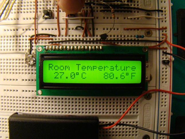
photo_3

photo_4

photo_5

photo_6_th

photo_7_th


PIC16F84A Gas Detector using GH-312 sensor

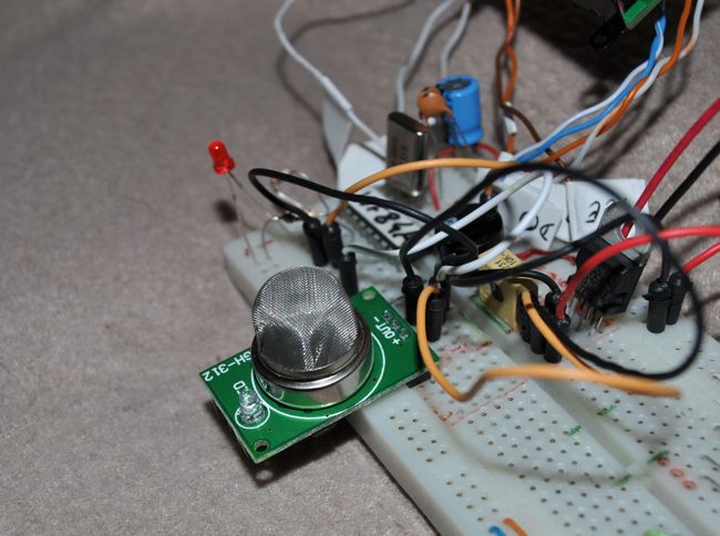
GH312Sensor

Introduction

This is a gas detecting circuit capable of sensing many different types of gases. 

The sensor used is the GH-312 and from the datasheet it is capable of sensing gases like smoke, liquefied gas, butane and propane, Methane, alcohol,hydrogen, etc.

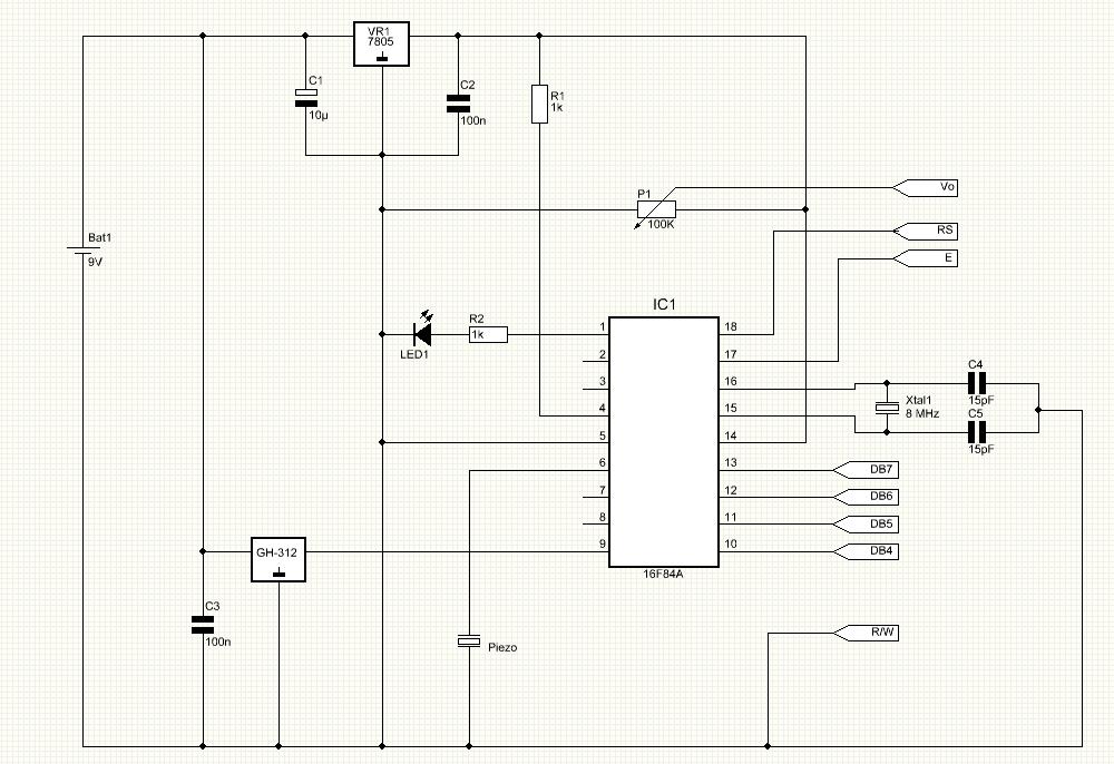
Schematic

GasDetectorSch

Parts List
R1                   1K resistor
R2                   1K resistor
P1                    100K potentiometer
C1                   10uF cap
C2                   100nF cap
C3                   100nF cap
C4                   15pF cap
C5                   15pF cap
Xtal                 8Mhz crystal
Led1                3mm red led
Piezo               Piezo
LCD                8X2 LCD
IC1                  16F84A microcontroller
VR1                7805 regulator
GH-312           Gas Sensor
Testing

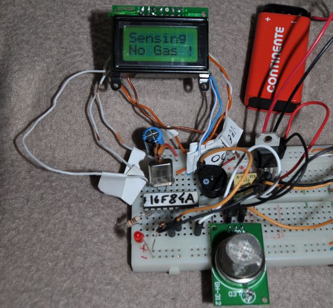
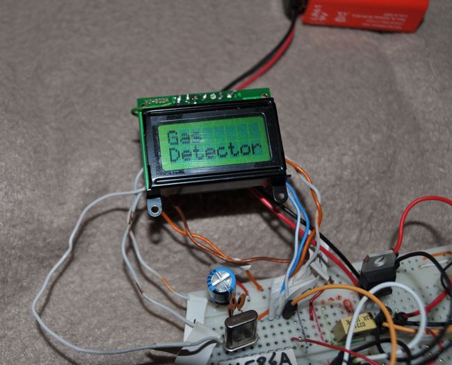
The first tests were made with the circuit mounted on a breadboard.   After initialization the circuit will enter a normal state where it detects no gas. The display shows “Sensing…No Gas !”.
Idle

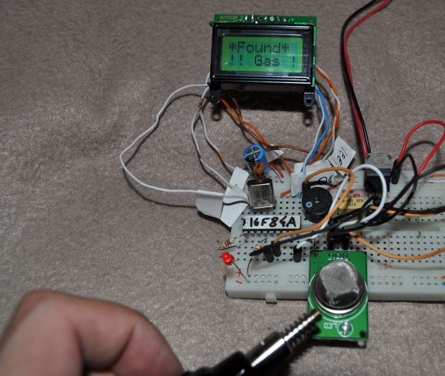
To test the sensor I used my portable gas soldering iron with the gas coming out pointed to the sensor.

The sensor is able to detect the gas and the microcontroller will trigger a flashing led warning and sound.

The sound is produced by a small piezo and the display show the message “Found Gas”.  

Testing

When the air is clean again and the sensor does not sense any gas, the circuit will return to it’s normal state turning off both led and piezo sound.

Photos

Initializing

Circuit is Initializing

Conclusion

It’s a pretty cheap and easy to assemble circuit.

Does not require too many parts and the microcontroller is very easy to find ( the famous 16F84A from microchip ).

Since it’s used a small lcd ( 8×2 ) this project can be portable.

Also this sensor senses several types of gas and it’s pretty stable.

Source code

The code is provided in hex format: GASDEMO.hex, We are sorry the source code isn’t available.

TOP PCB Companies