IR remote extender

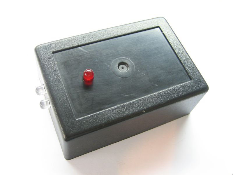
photo_1

This project describes how to build an IR remote control extender / repeater to control your electronic appliances from a remote location.
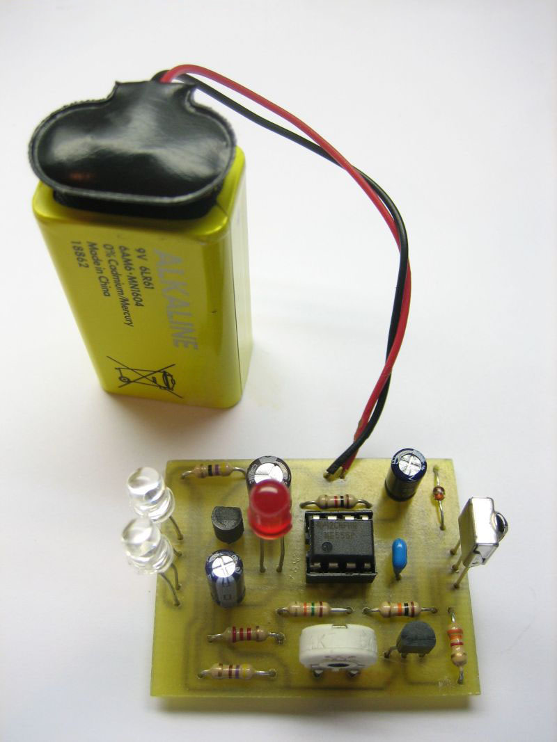
An IR detector module receives IR signal from remote control and two IR leds are re-emitting the signal to the appliance. You can place the IR emitting leds close to the device you would like to control using some wire and keep main unit close to remote control location. In the image at the left LEDs are soldered on the board. The circuit consists of three main parts, the IR receiver module, a 555 timer configured as an oscillator and the output / emitter stage. We will describe circuit operation below.

Circuit is designed by Andy Collinson and can be found here:http://www.zen22142.zen.co.uk

IR Signal

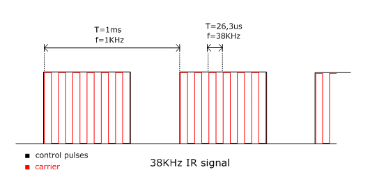
The IR signal emitted from a remote control caries the information needed to control the appliance. This signal consists of pulses that code 0 and 1 bits, instructing the appliance to do a certain operation. One of the most common protocols used to code the IR signal is Philips – RC5 protocol. The signal consists of two parts, the control pulses and the carrier wave as seen in the image below.

image_1

A common frequency used for the carrier is 38KHz and control pulses frequency is in the range of 1-3KHz. The carrier signal is modulated by the control pulses and the resulting signal is emitted by remote in IR band of the electromagnetic spectrum. IR band is invisible to the human eye. You can see if an IR led is emitting light or not using a camera. Point the camera to the led and you will see that light comes off.

Circuit description

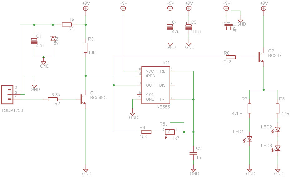
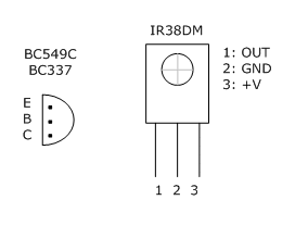
IR signal is received by TSOP1738. TSOP1738 is an infrared receiver at 38KHz. At the output of the infrared receiver, we get a demodulated signal that means we get the low-frequency control pulses. The infrared receiver is powered from C1, R1, and Z1 that forms a 5V power supply. With no signal received, infrared detector output is high and Q1 is on, so pin 4 of IC is LOW and the 555 timer is in the reset state. Q1 also acts as a level shifter that converts 5V signal of TSOP1738 to 9V signal for IC1.

schematic

When HIGH control pulses are appearing on TSOP1738 output then timer 555 (which is configured as an oscillator) starts to oscillate at a preset frequency, for the duration of each data pulse. That means that at pin 3 we get a signal that is similar to the modulated source signal. It has a carrier component and a control pulses component. The oscillating frequency of 555 timer is set by R4 and C2 and pulse period is given by:

T = 1,4 R4 C2

Trimmer R5 is used to fine-tune oscillating frequency at 38KHz. That’s equal to the carrier frequency.

The output stage is formed from R6, Q2, one red LED, two IR LEDs, and two current limiting resistors R7 and R8. Q2 is connected as a voltage follower, which means when the base of Q2 is HIGH transistor is ON allowing current to flow through LEDs. LED current is set by R7 and R8 according to the following formula:

So IR LEDs are emitting a signal that is similar to the signal received by TSOP1738, which means it repeats the signal received at higher infrared radiation intensity. The red LED is used as an optical indicator of the output signal. The circuit can be powered from a 9V battery.
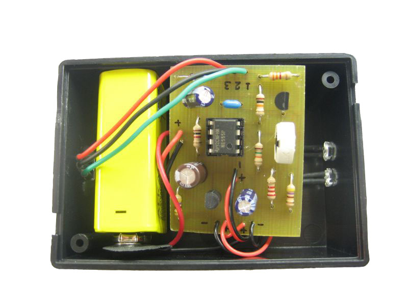
photo_2
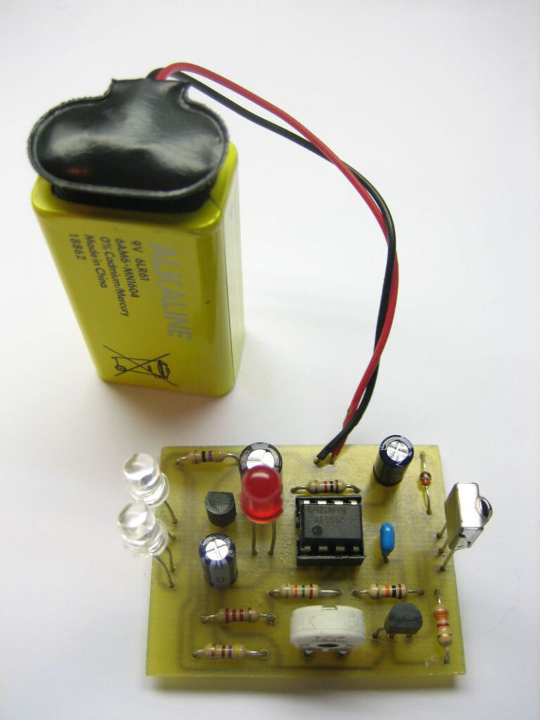
photo_3

Parts List

PartValue
R11k
R23k3
R310k
R415k
R54k7 trimmer
R62k2
R7470R
R847R - 1/2W
C147uF - 16V
C21n - polyester
C3100uF - 16V
C447uF - 16V
Z15V1 zener
Q1BC549C
Q2BC337
IC1NE555
LED1red LED
LED2-3IR LED
IR receiverTSOP138 or IR38DM


image_3

Testing

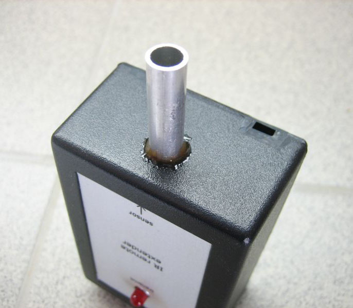
Before powering the circuit, remove IR LEDs. With no input red LED should be off. Now press a button on a remote control, red led should flicker. If that’s the case then your circuit should be working ok. Install IR LEDs. We found during testing that IR signal emitted from remote and IR signal emitted from circuit are interfering each other and that’s make receiving device not to react on receiving the signal, this happens when IR from remote and IR from circuit’s LEDs are on the same room. To solve that we must isolate the IR beam of remote control. To do that we used a thin pipe in front of infrared sensor as seen in photo below, so that the beam emitted from remote hits the sensor directly. Another solution to this would be to put the emitting LEDs on a different room.
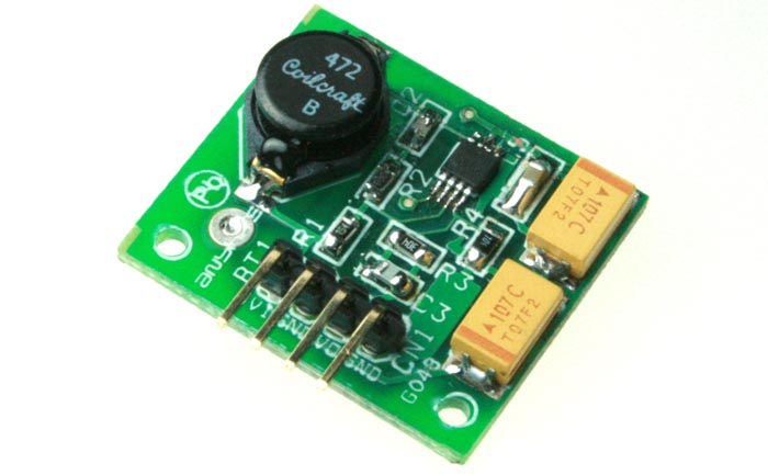
photo_4

Installation

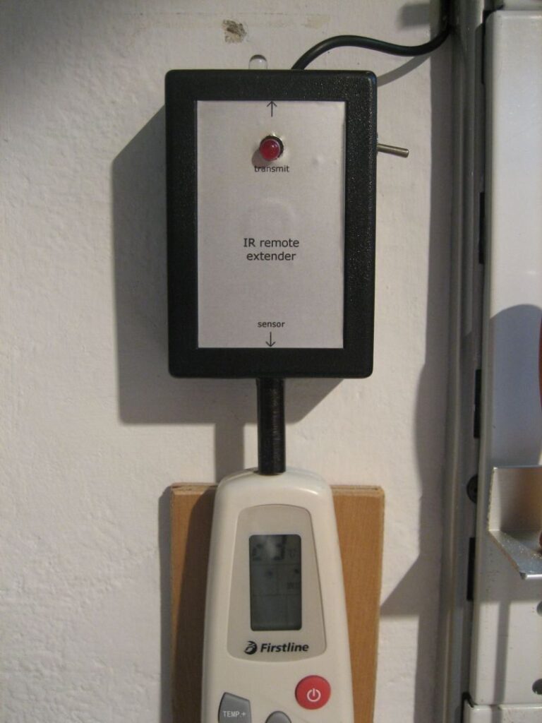
We installed the circuit on the wall the way you see on the photo below. You can see that remote control led is optically isolated from surround. You can also notice that one LED is remotely placed near the device we would like to control.

photo_5

References

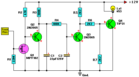
Simple Touch Switch

schematic


Description

The MPF102 (Q1) can be replaced with a NTE451 or ECG451, but still widely available. JFET-N-CHAN, UHF/VHF AMP.
The 2N3565 (Q1/Q2) can be replace with a 2N2222(A), BC107, BC108, BC109(A/B/C), NTE123A, or ECG123A.
The TIP31 (Q3) can be replaced with a NTE196 or ECG196, but is a common type and widely available.
NO suffix.

The ‘Touch Plate’ can be anything non corrosive. I use a silver quarter. You can also use a small relay instead of the #53 bulb. The phone number for DigiKey is 1-800-Digi-Key.

Parts

R1 22Meg resistor
R2 47K resistor
R3,R4 100K resistor
R5,R6,R7 2K2 resistor
C1 Capacitor, 22uF, 25V
C2 Capacitor, 22uF, 25V
Q1 MPF102
Q2,Q3 2N3565
Q4 TIP31
La1 Bulb, #53

iButton electronic lock

Sch

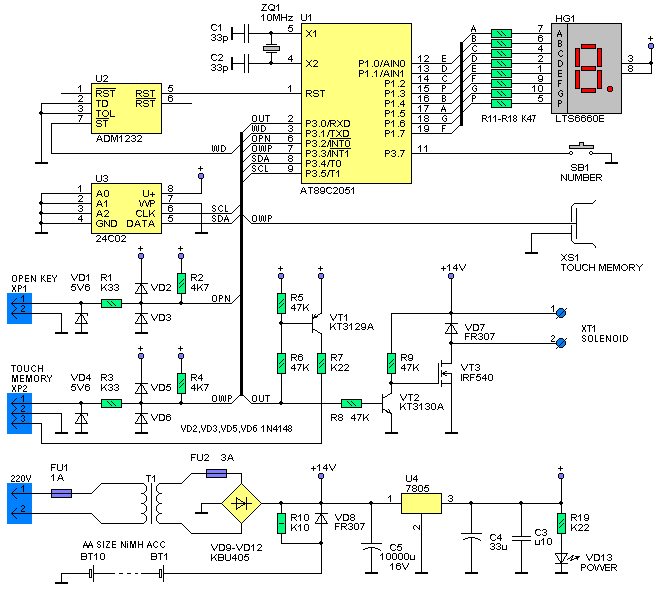
Fig.1 Schematic diagram of iButton electronic lock

Since iButton DS1990A introduced in market from Dallas Semiconductor (MAXIM), it has been used in many applications concerning security, access control systems etc. In this project we will use iButton as a key to an electronic lock. This electronic lock can use many different kinds of iButtons and can store up to 9 different keys. One of the keys is the master key and is permanent stored in memory. With the use of master key we can add or remove slave keys.

This electronic lock can be used with any type of iButtons you may already have, since the only thing needed is the internal serial number, that’s different for every iButton. The command used to read the serial number is the same for all iButtons. The iButton family code that goes with every iButton, can be anything and is calculated as part of the whole serial number. We must also notice that DS1990A series iButtons are the cheapest.

Logo

iButton

This electronic lock designed to work stand-alone and it’s easy to construct. What the user sees (outside of the door for example) is a iButton socket and a led. From inside the door, we can open it using a simple push button. For the actual lock of the door a solenoid and a bold are used. Solenoid must be rated at 12Vdc. iButtons serial numbers stored in memory can be removed and updated when needed. One master key is used to manage the rest of them. Totally a number of 9 different keys can be stored in memory.

Schematic diagram is shown at figure 1. The circuit is build around an Atmel AT89C2051(U1) microcontroller. The port 1 (P1) of mcu is used to connect a 7-segment common anode led display. This led display will be used on the programming of additional keys. For the same reason a push-button labelled SB1 is connected on P.3.7. Storage of iButtons serial numbers is done on a 24C02 EEPROM (U3). It is connected on P3.4 (SDA) and P3.5 (SCL) of U1. The external iButton socked is connected on port P3.3 via XP2 pin array. The rest of components VD4, R3, VD5 and VD6 are used for protection of mcu ports. One pull-up resistor R4 is used as required from 1-wire protocol. An additional iButton socket is connected parallel with the predefined at pins XS1. This one is used for programming the keys. The door OPEN button is connected on P3.2 through XP1 connector, using the same protection components as above. The solenoid that does the lock is connected on XT1 connector. Solenoid is controlled from a power MOSFET IRF540 (VT3). Diode VD7 is added to protect MOSFET from voltage strikes due to solenoid inductance. Transistor VT3 is controlled from VT2, which reverses the logic state that’s appears on P3.0, so on VT3 we have output 0V and 12V. This additional transistor is useful as it translates the mcu logic levels to 0V and 12V, capable to drive the solenoid.

A led is used to indicate the state of the electronic lock, which is controlled from the same pin as the solenoid, using transistor TV1. This led is connected to the board using the same pin array XP2. But we need to ensure that the circuit will always work without supervision. For that reason we added ADM1232 (U2) that does the mcu reset pin control. This chip have a counter and voltage test circuits inside it. On pin P3.1 mcu produces pulses when it works right. If for a reason mcu freeze then U2 send it a reset pulse and work is resumed.

This electronic lock has it’s own power supply on board, consisting of transformer T1, bridge rectifier VD9-VD12 and voltage regulator U4. As power backup an array of 10 AA batteries is used (BT1-BT10). Total capacity is 800mAH. When the circuit is connected on main voltage the battery pack is charged via R10 with a current of 20mA. This current is equal to 0.025C (where C is the batteries capacity) and that’s a very small current depending on total capacity. That’s put the battery on a steady charge to compensate losses among time and no charge completion detection is needed. That can be done as the excess energy is consumed in heat, that can not harm batteries as its low.

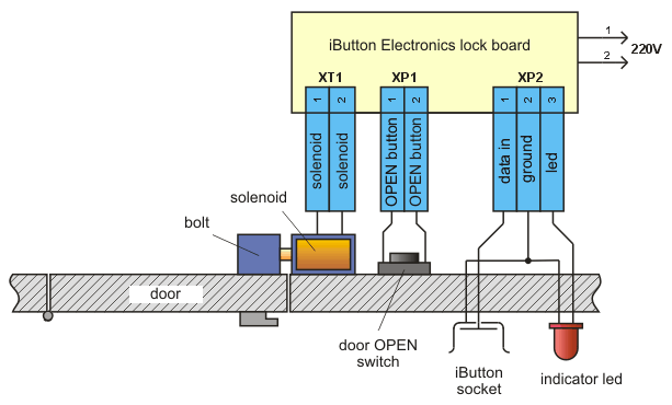
Overall board dimensions are 150х100х60mm. The most components are placed on the board, including the transformer. Batteries are placed on battery holders. In the place of AA batteries we could use a 12V sealed Lead – Acid battery. External components are connected on board with 2 or 3 pin connectors. Part numbers HG1, SB1and XS1 are used only in programming mode so can be placed inside the plastic enclosure. Led VD3 can be placed on the face of enclosure, to indicate proper powering of board. A connection diagram is show on figure 2.

Block

Fig.2 Connection diagram

When the door goes open, a 3 sec pulse is triggering the solenoid. When we press the door open button the door remains open as long as we push it.

The electronic lock can register 9 keys, plus one master key. Master’s serial number is stored inside mcu. The rest of keys are stored on the external memory under slot 1 to 9. To add or remove a new key you should have the master key. Also master key can be used to open the door.

Man_P

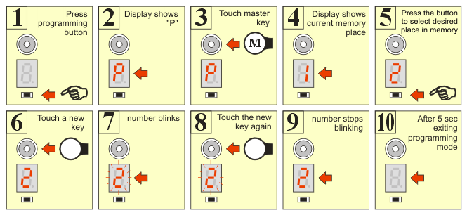
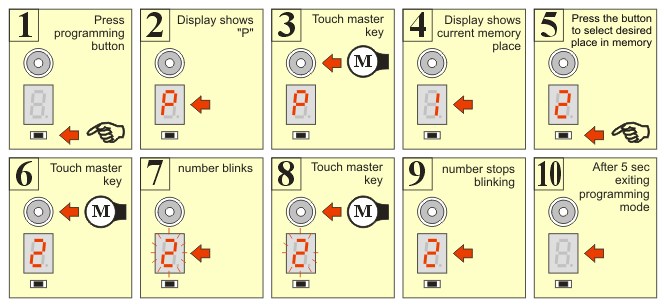
Fig. 3 Programming steps for adding a new key


To add a new key, the following steps should followed:

  • Press programming button.
  • Led displays letter «P» that indicated you entered programming mode
  • Touch the master button in socket.
  • Led displays number «1». That’s the current selected slot in memory.
  • Push the programming button to select a different programming slot for your new key.
  • Touch the new key to the socket.
  • The number on led display blinks, indicating ready to program.
  • Touch again the new key to confirm registration to memory.
  • If successfully registered the display stops blinking.
  • After 5 seconds, the program exits from programming mode.


The programming procedure to register a new key is displayed schematically on figure 3.


If you want to register more keys, then from step 9 you can go directly to step 5. These steps can be revised as many times as you like.

If after step 7, you find out that you selected wrong slot number and you don’t want to loose that key, press programming button or just wait 5 seconds. When you press the button the slot number increases by one and memory hasn’t changed yet. If you wait 5 seconds, programming mode will exit and nothing is going to register in memory.  Generally in any programming step, you can wait 5 second to exit programming mode.

To remove an already registered key, you follow an almost same procedure, using only the master key. Basically, it’s like registering the master key on the memory slot you would like to erase. This procedure is shown on figure 4.

Man_D

Fig.4 Programming steps for removing a key.

During programming mode, the door will only open with the press of the OPEN button. Also, because the two iButton sockets are connected in parallel, you should avoid simultaneous touch of keys on both sockets.

Master’s key serial number is stored on mcu’s program memory, beginning from address 2FDH. The length of serial number is 8 bytes. The serial must be equal that is printed on top the iButton case, reading from left to right. On memory address 2FDH the control byte is registered, then on address 2FEH – 303H the next six bytes are registered, beginning with most significant byte. Finally the family code byte is stored on address 304H. For example a complete serial code should look like: 67 00 00 02 D6 85 26 01

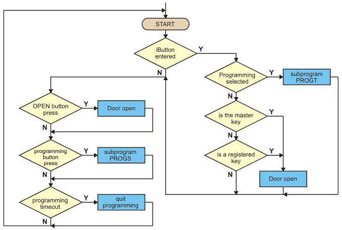
The software block diagram shows on figure 5. The program starts, asking if a key has entered. If a key is entered, then it goes on reading the internal serial number. The next step is to check if this is the master key or another key already registered in memory. If the key is verified then the door is opened. Also the OPEN push button is checked, and if it’s pressed the door opens.

Main

Fig.5 Software block diagram

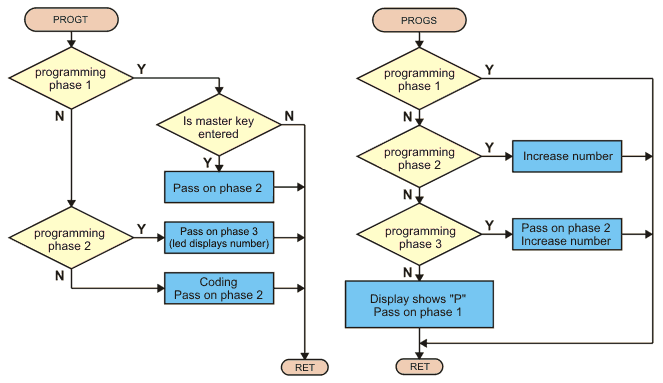
For the programming mode there exists two subprograms: PROGT and PROGS, whose block diagrams show in figure 6. The first is called when the serial number is read, in the programming phase and the second is called when the programming button is pressed. Programming of a new key is completed in three phases. When we press the programming button, we enter the programming mode. In this state the led displays «P» and the serial number of the key is checked to see if this is the master key, because this key is required to proceed on programming steps.

If this is the master key, we proceed on phase 2. Now, led is displaying the number of current selected memory slot, changing by pressing programming button. If we touch the key again, then it is registering on memory and we pass to phase 3. If we touch another key, this is also registered and we pass to phase 2. With the press of the button, we pass on phase 2 without registering any key.

If we don’t touch anything in a period of 5 seconds, the program exits from programming mode.  Block diagrams of figure 5 and 6 are simplified, but they give as an overall sense of program functionality.

It’s upon your desire to extend the capabilities of this program, as it’s open source, to fit your special needs.

Prog

Fig.6 Programming mode subprograms block diagrams

Water Level Alarm

photo


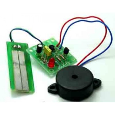
This project is a water level alarm.

Description

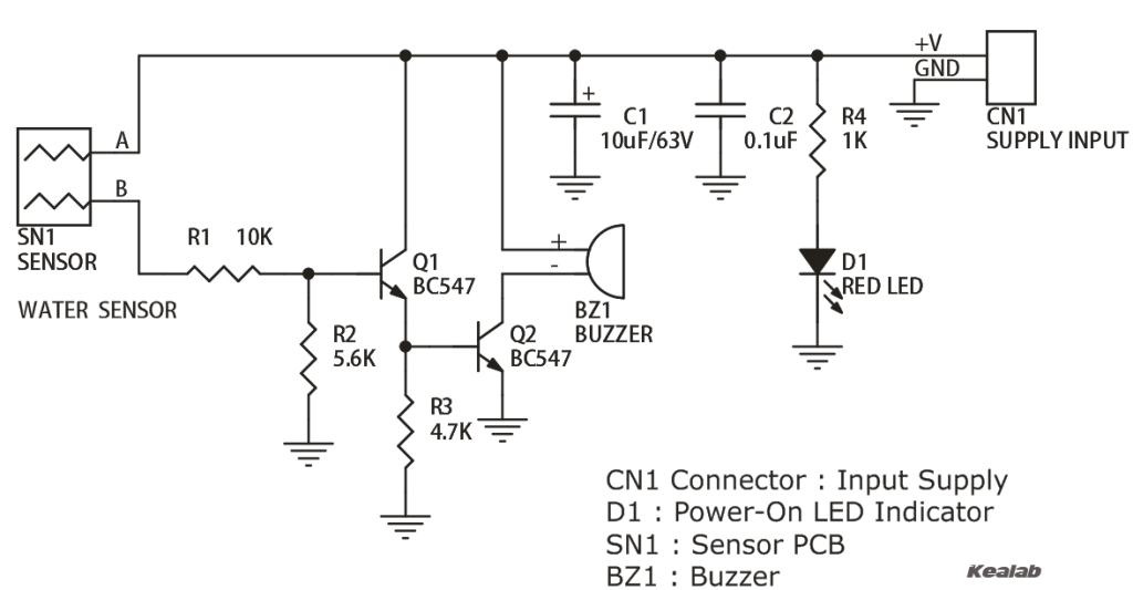
Water Level Alarm is a simple project to detect and alarm once the water level in tank or Aquarium reaches at certain level. Circuit is based on popular NPN transistor BC547 which act as switch, Sensor also made on PCB, when the water reaches the sensor PCB, base of transistor connected to positive supply, in consequence transistor act as switch and activate the buzzer.

Specifications

  • Input: 9 VDC @ 40 mA (Supply range 5V to 12V DC)
  • Works good with 9V PP3 Battery
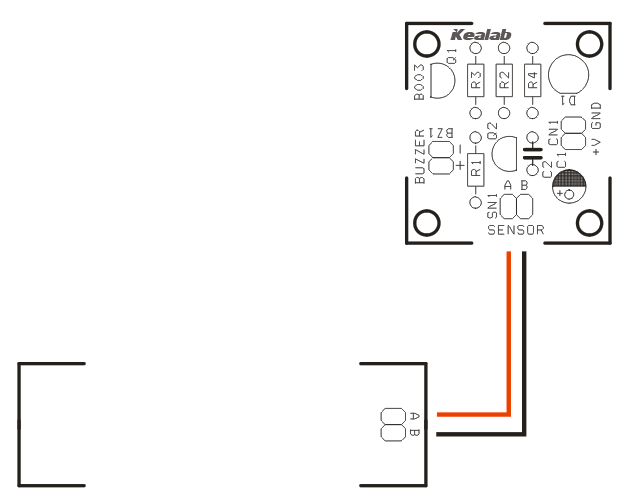
  • Project has two PCB ( 1. Sensor 2. Buzzer driver)
  • Output: Buzzer
  • Buzzer Included
  • Terminal pins for supply voltage
  • Power-On LED indicator
  • Four mounting holes of 3.2 mm each
  • PCB dimensions 32 mm x 35 mm

Schematic

schematic


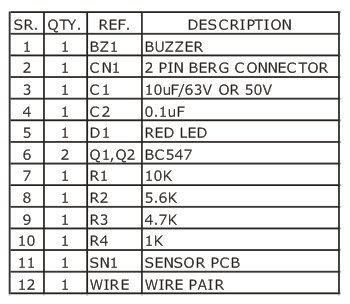
Parts

BOM

Connections

Connections

AMP – Arachnoid Mobile Platform

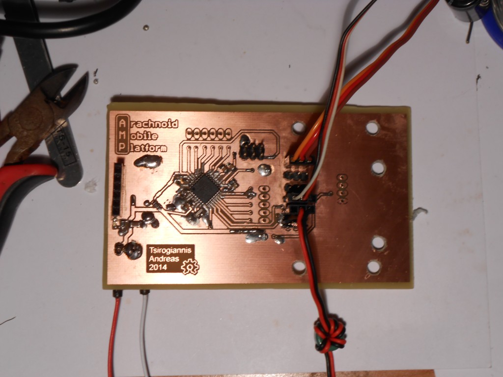
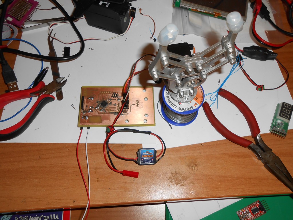
photo_2

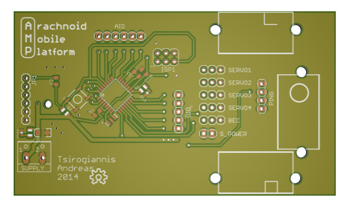
The Arachnoid Mobile Platform is an open source robotics development platform used to make small autonomous moving robots. It can be either configured as a four-legged robot, or as a two wheeled robot. The PCB board holds all the electronics and mechanical components, and also serves as the chassis of the robot.

Project Status: Current build is rev 1.1 assembled  8/2/2014

Description

The Brains

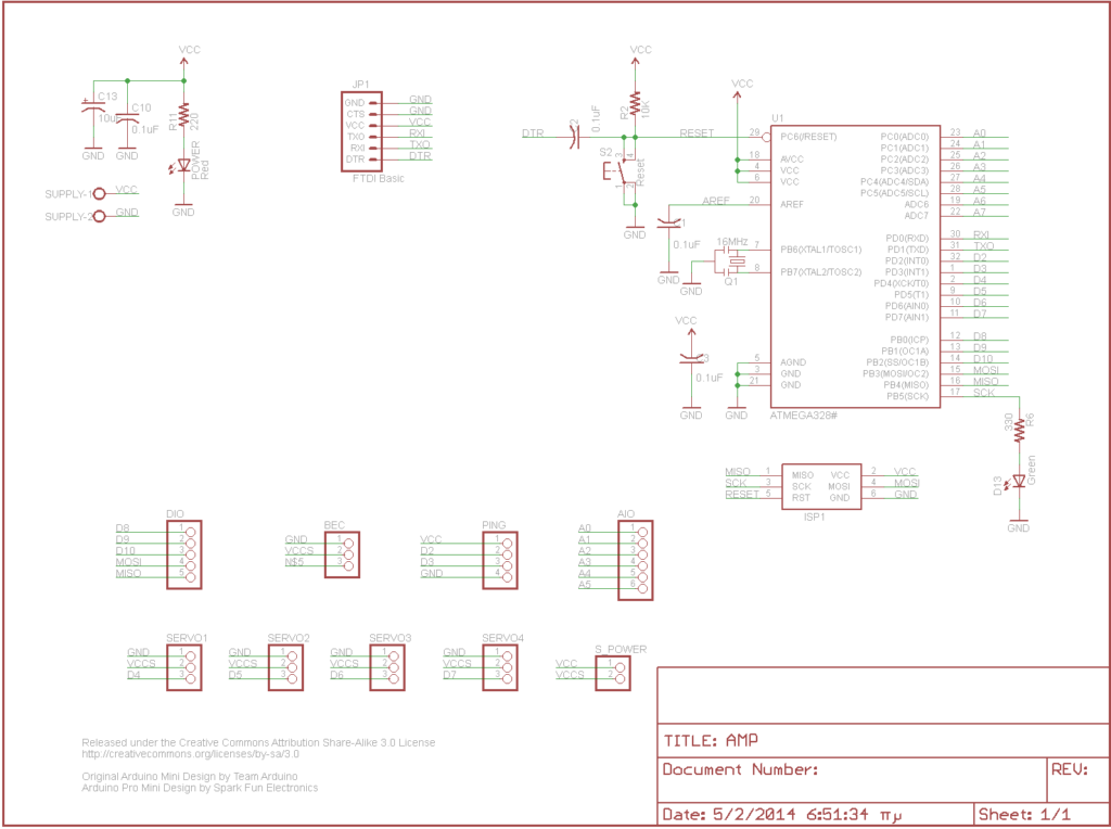
The whole project is based on an ATmega328-AU (The SMD version of the infamous ATmega328) and is flashed with the standand Arduino pro mini bootloader. Consequently, the board can be easily programmed using the Arduino IDE platform. As for the programming hardware, there are two interfaces for the user to upload his/her code. There is an FTDI headerwith the standard pinout (on the leftmost side of the board marked “FTDI master”), and an ISP header (marked as “ISP”) for using with a compatible Atmel SPI programmer. The tool used here for uploading the code to the board is a classic FTDI FT232 USB to serial interface board. The microcontroller runs on 5V DC.

Movement

The robot uses 2 continous rotation servos for its movement when configured as a wheeled robot, and three continous rotation servos when configured as a four-legged robot. Aditionally another is used for panning the ultrasonic PING sensor for obstacle avoidance mentioned below. All the servos used in this examle are HXT900 9g servos, from hobbyking.com. Any standard 9g micro  servo should be fine for this project (provided it is bought/modified as continous rotation for the drivetrain).

Headers and sensors

The board contains 4 headers for direct servo connection (marked as “Servo 1 through 4”) on the board as well as as an ultrasonic HC-SR04 sensor direct interface (marked as “PING”). The ultrasound sensor mounts on the center servo which allows it to turn in a 30-50 degree radious in order to “scan” its surroundings and find the path with the least obstacles in place.  Additionally, all the remaining digital and analog I/O pins, are brought to their respective headers for future expansion (Digital I/O is brought to the “DIO” header and analog IO is brought to the “AIO” header).

Power

A single 5V power source is necessary to run the entire board. The supply voltage can be provided either to the screw terminals directly, or through the “BEC” header, using a standard hobby UBEC (the name comes from “battery ellimination circuit”, just a fancy name for a 2-3 cell lipo battery to 5volt regutator). The one i found luck with is the cheap and marvelous 5V/3A that hobbyking sells  (www.hobbyking.com). Beneath the BEC header there is a two pin jumper that isolates the servo and the microcontroller supply. It can be used for either powering the servos from a different heavy-duty power source or disconnecting the servo load from the micro in order to flash it with new firmware.

Software

The software is currently in developing stage and is going to be public available when finished. Feel free to write your own code and upload it to electronics-lab.com.

Schematic

schematic

Photos

3D_pcb_top_th

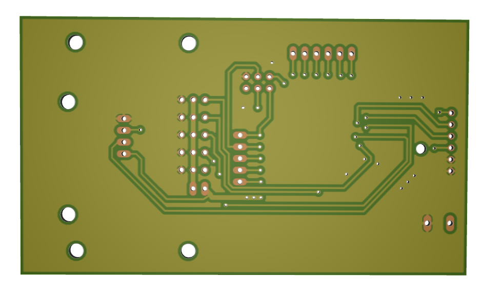
3D_pcb_bottom

photo_1

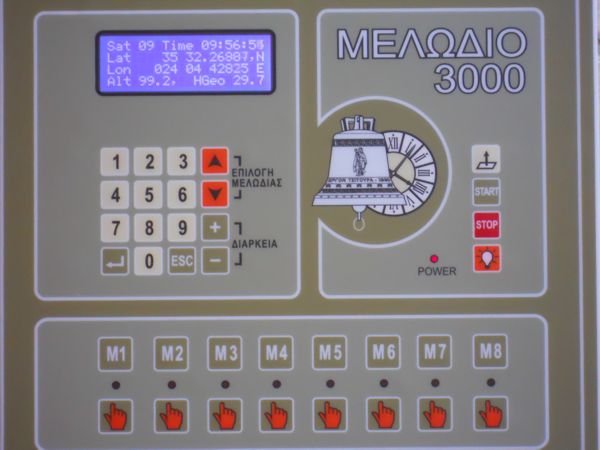
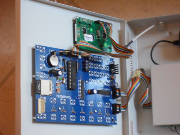
Church bell Controller

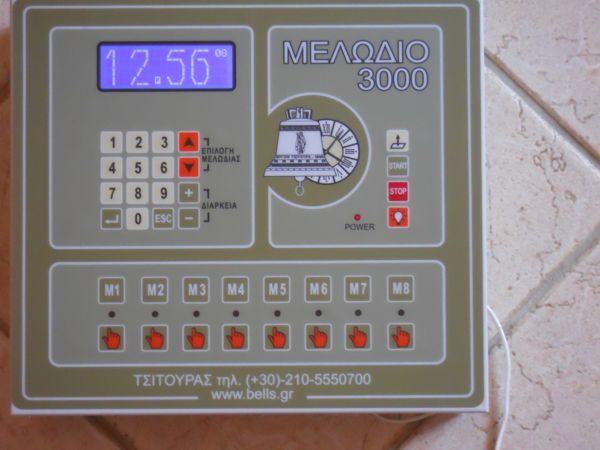
photo_7


Description

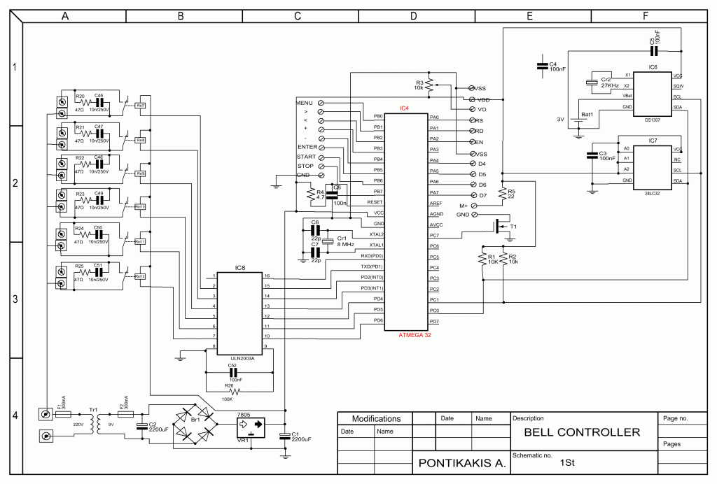
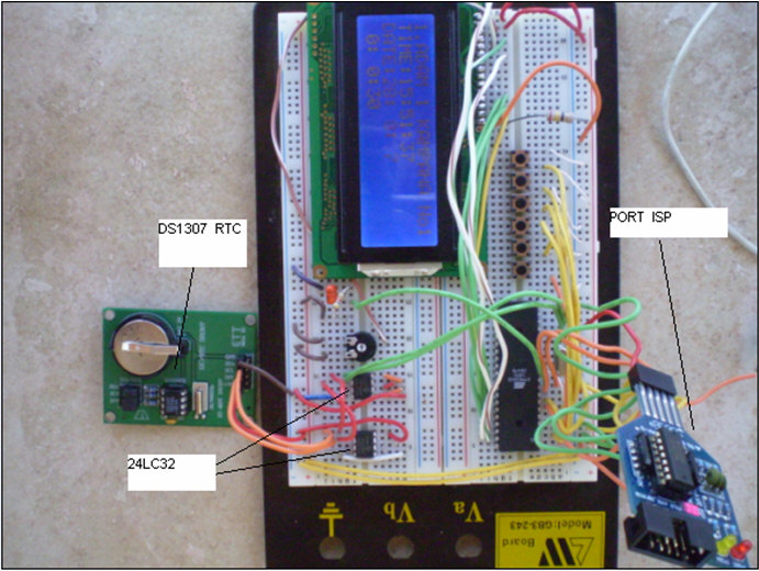
This circuit is a church bell controller. Basic component is an ATmega32 microcontroller. At the circuit 1 24LC32 eeprom memories is being used.

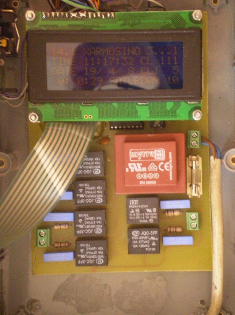
As control I created a menu who will be appeared on 4×20 LCD (Liquid Crystal Display). The menu browsing can be done by 6 buttons at the face of the circuit’s box (Menu, Up, Down, Enter, Start, Stop). The all firmware binds about 30Kbytes flash memory and can be increased by adding new features-functions. This program has been written in C with CVAVR compiler.

The idea of this circuit is being given by a friend of mine who has an foundry and he is building bells. I have made the PCB by my self.

Features

  • More 75 different melodies (ADAM, PANYGJRJKO, AGJORJKO, etc)
  • Control of electrometrical clock of church with the production of pulse of duration 1Sec each one minute.
  • Automatic correction in case of power loss.
  • Percussion of clock each half but also entire hours, with possibility of choice of hours of silence (for tourist regions and hours of common quietness).
  • Manual correction of electromechanical clock.
  • All regulations become with the help of guidance (menu, up, down, enter, start, stop)
  • When it runs a rhythm we have the possibility of increase or decrease her speed, the information will stored in memory 24LC32.
  • Display time (DS1307), with backup battery.
  • All the in formations are displayed on 4X20 LCD.
  • Control up to 5 bells and 1 clock.
  • The user create his own program

Schematic

Bell_controller_sch

Photos

Breadboard


photo_1

photo_2

photo_3

photo_5

photo_6

2.4V to 5V Step Up DC-DC Converter

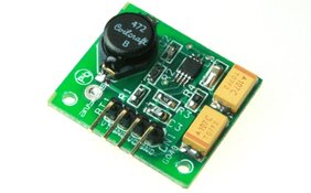
Step Up Dc-DC

This project is a step up DC to DC power converter able to convert 2.4V – 5V to 5Vdc.

Description

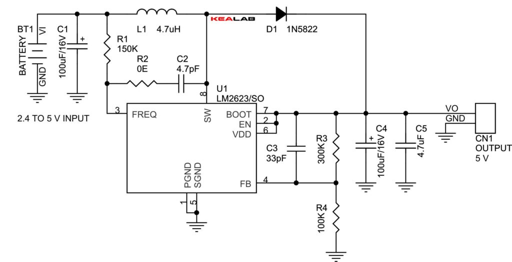
This project has been designed around Texas Instrument’s LM2623 IC, The LM2623 is a high efficiency, general purpose step-up DC-DC switching regulator for battery powered and low input voltage systems. It accepts an input voltage between 2.4V to 12V volts and converts it into 5V DC. Efficiencies up to 90% are achievable with the LM2623.

Features:

  • Good Efficiency over a very wide load range
  • Very low output voltage ripple
  • 2.4V to 5V (Possible Input Supply up to 14V operating voltage)
  • 5V output voltage (Other output voltages possible by changing R3 and R4)
  • 600mA output current

Application:

  • Hand held instruments
  • Cameras, PDA, Cellphones
  • White LED driver

Schematic

image description

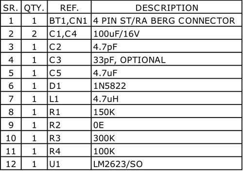
Parts List

image description

+/-12V Dual Power Supply

Product_Image

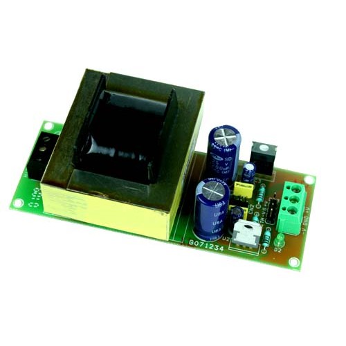
This project is a solution to power up most of devices or projects requiring dual (+/-12V) power supply.

Description

Symmetric +/-12 VDC power supply has been designed for audio applications, can power up microphone pre-amplifier, audio buffers, audio mixer, distributions amplifier, headphone amplifier, VU meter and few o other equipment or projects required dual supply.

Specifications

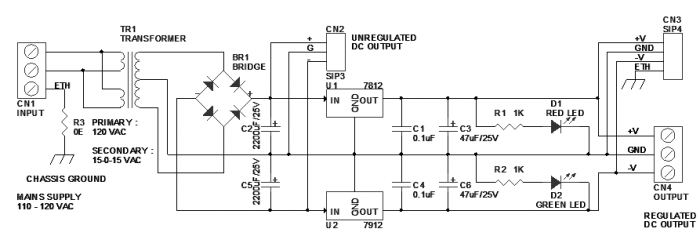
  • Mains supply input 240 VAC
  • Step Down Transformer 15-0-15V AC @ 350mA.
  • Output +/- 12 VDC Dual, 350 mA
  • Regulated Low ripple DC output
  • Earth connection for chassis ground
  • Onboard regulator for stable supply
  • Dual output LED indication
  • Supply input & output via screw terminal connector
  • Dual unregulated output +/- 22 VDC via berg connector

Schematic

Schematic


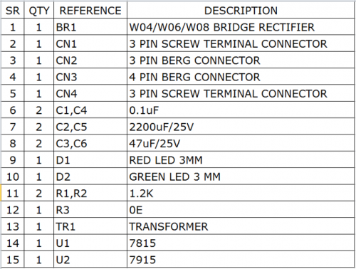
Parts

BOM_th

Dual Adjustable Power Supply

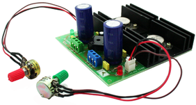
004_PIC

This project is a solution to power up most of devices or projects requiring dual (+/-) adjustable power supply.

Description

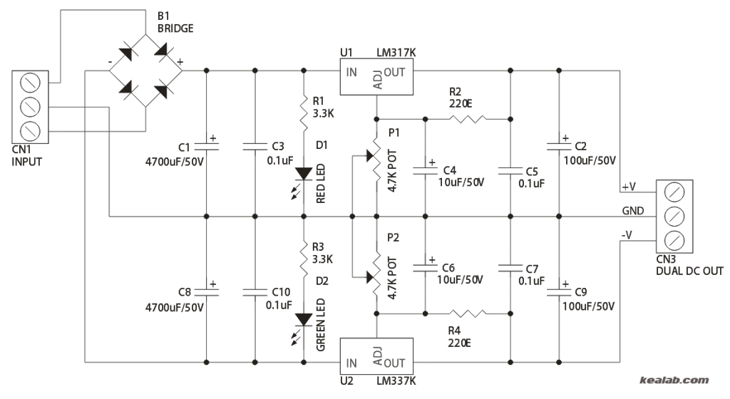
The circuit is based on LM317 positive and LM337 negative voltage regulators. LM317 series of adjustable 3 terminal regulator is capable of supplying in excess of 1.5A over a  1.2V to 30V DC output range, due to TO3 package of  IC and large heat sink the power supply can handle maximum load  current.

  • Output: +/- 1.2 to 30V DC
  • Output Current: 1.5Amps
  • Supply Input: 24V-0-24V AC, 2Amps Center tape Transformer
  • CN1: Transformer Connections
  • CN3: +/- Dual Supply Outputs
  • P1: Positive Voltage Adjust
  • P2: Negative Voltage Adjust
  • D1: Positive Power Indicator
  • D2: Negative Power Indicator

Schematic

004_Schematic

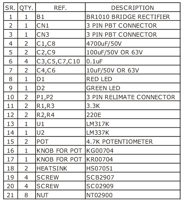
Parts List

004_BOM

9V to 48V DC-DC Converter

photo_1


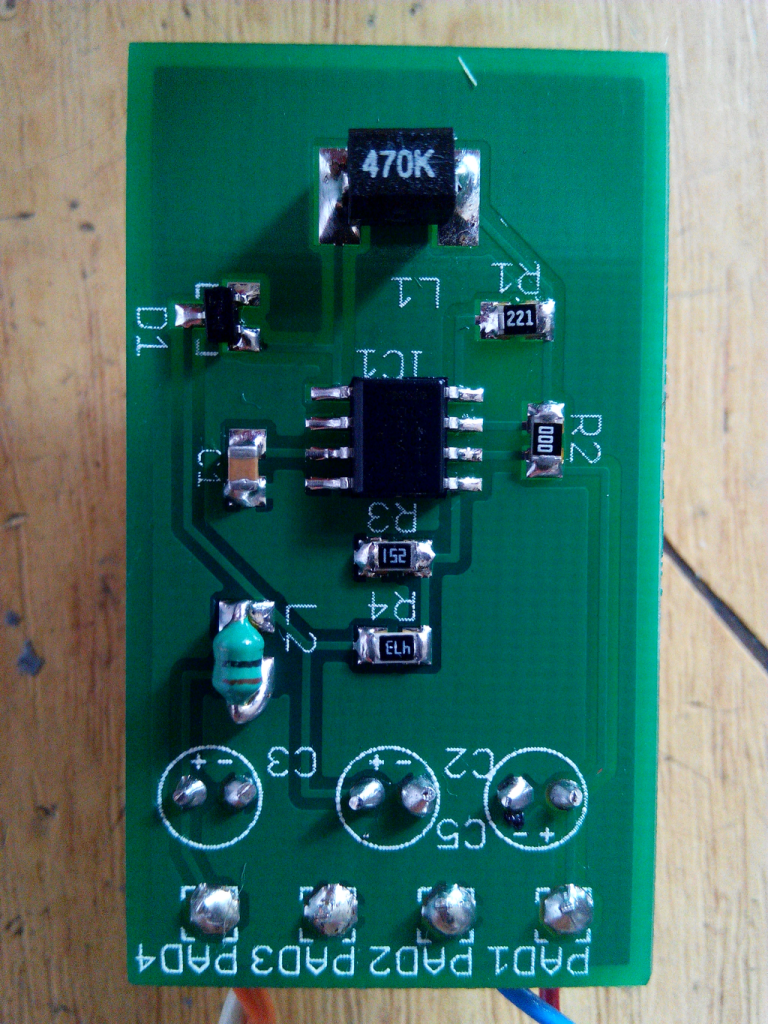
This project is a 8-12Vdc to +48Vdc DC-DC converter based on MC34063 switching regulator.

Description

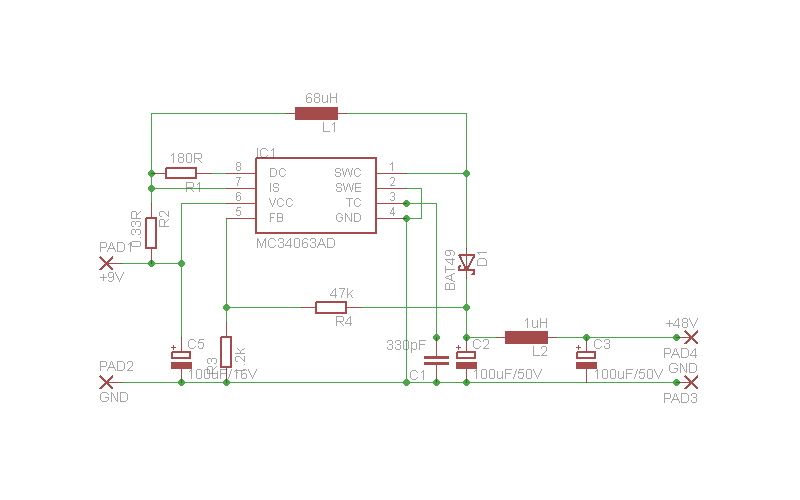
It’s a simple project of a DC-DC converter to make a phantom power supply for professional microphones. It can deliver 15-20mA at 48VDC. It ‘s based on MC34063 DC-DC step-up, step-down and boost converter. Input is between 8-12V DC and the output +48VDC/10-20mA.

Schematic

Schematic

Photos

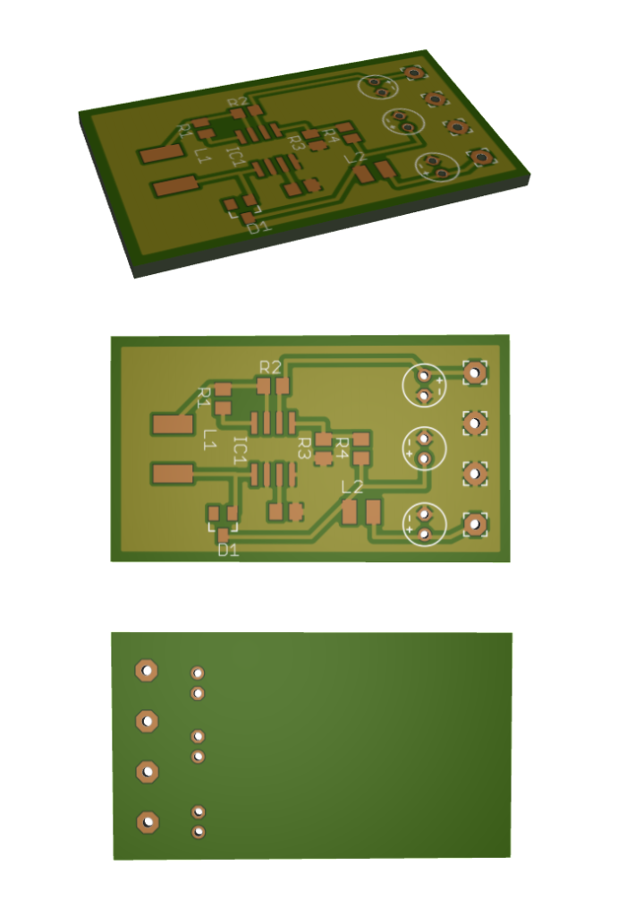
3D_PCB

3D PCB renderings

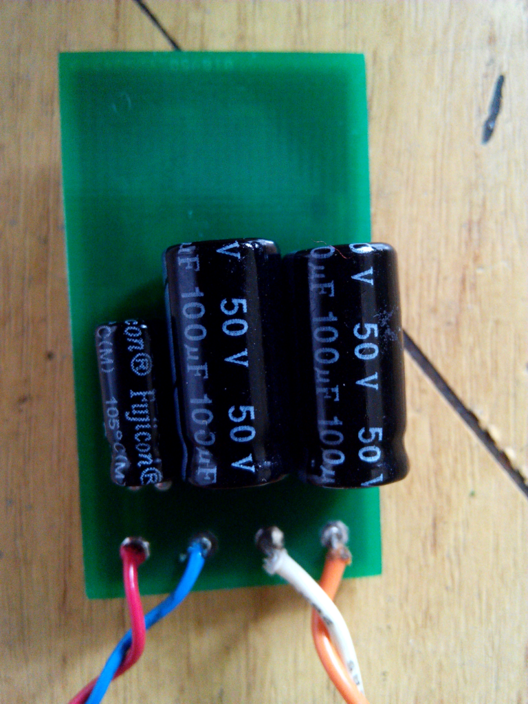
photo_2

MC34063 Datasheet

TOP PCB Companies