LED Binary Clock – Arduino Shield Compatible

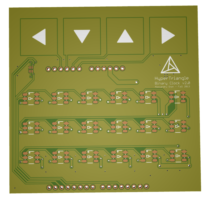
3D_PCB_1

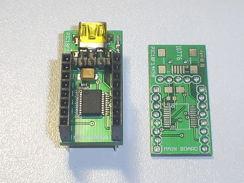
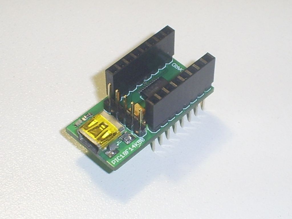
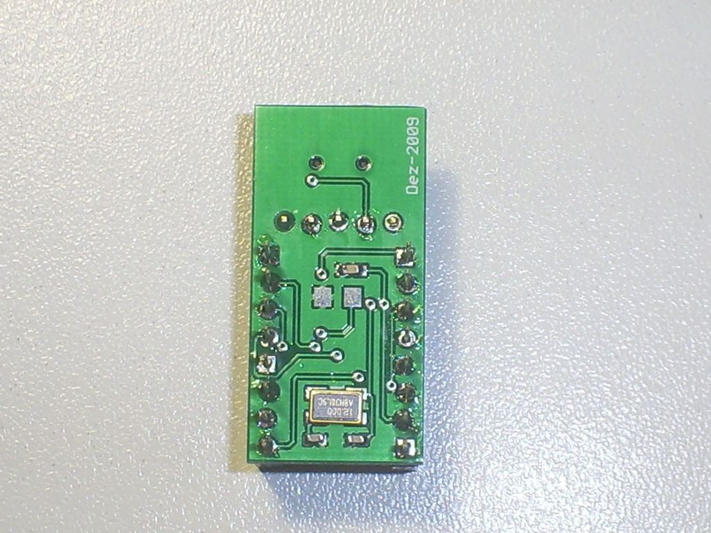
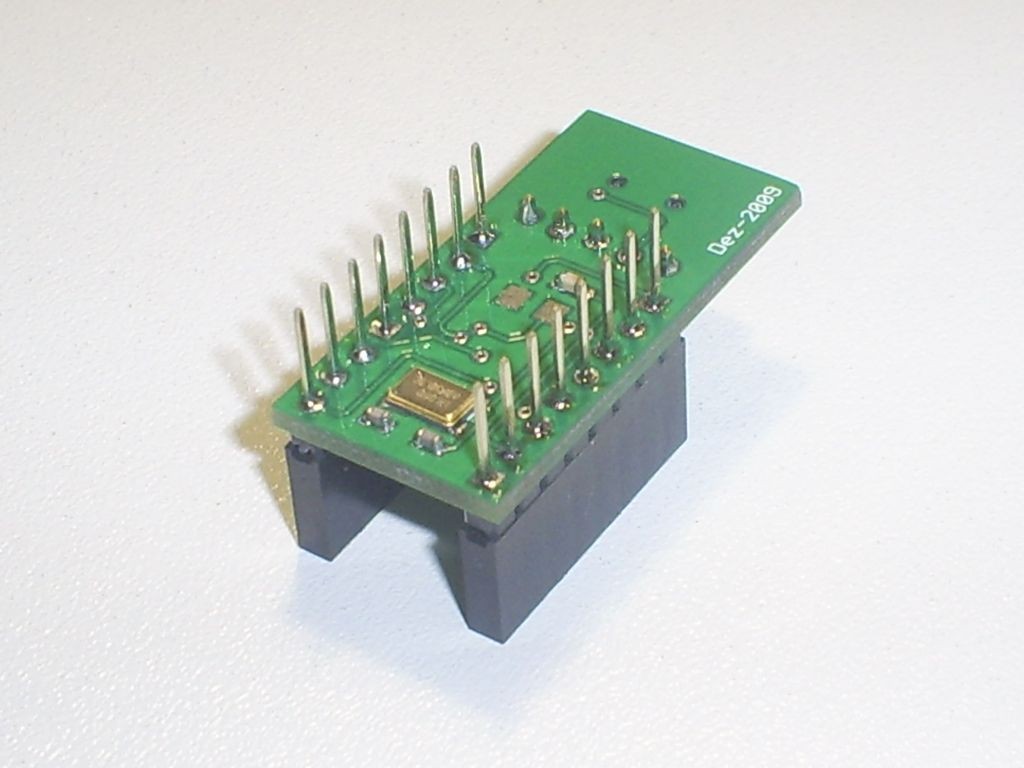
This shield is meant to be used as a Binary Clock on top of an Olimexino-5510. Other ‘duinos might work too.

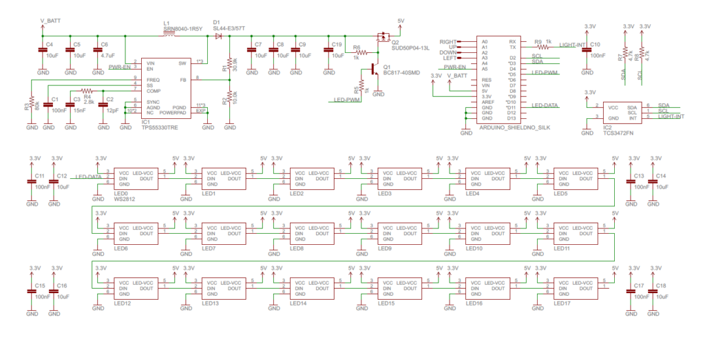
Schematic

schematic

Description

LED Matrix

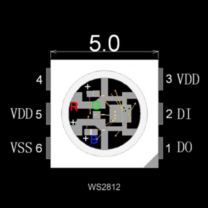
The main feature of the Clock is the 6×3 WS2812 RGB led matrix. These leds contain a little controller that accept a serial protocol for the color data and they handle the PWM. They’re also chainable meaning that only one pin(D11, LED-DATA) is required to quite all of them. The protocol is described in the WS2812 datasheet, there exist a couple of libraries that handle them, including one for Arduino. In my case i’m using an ASM library for the MSP430.

led_ws2812

Power Supply

The Olimexino-5510 has a connector for a battery. But it just connects the battery to the 5V rail, the battery could go as low as 3V. The WS2812 aren’t meant to run that low, specifically the Blue led get a lot dimmer. In order to fix this I incorporated a SMPSU that can get 5V from the battery voltage. It could in theory handle as much as 2A. The design was done with TI Webench, all parts are the same as the suggested ones.

The WS2812 leds are very bright, so in the darkness this might be a problem. One could dim them by sending them a darker color but this reduces resolution. Q2’s purpose is to PWM is the 5V that the LEDs in order to dim them externally. This essentially gives another scaling factor for the brightness. It’s a similar principle to how dynamic contrast works in TVs.

Capacitive Touch Pads

This shield contains 4 touch pads for UI purposes. The MSP430 chips have a nice peripheral where one can make an RC oscillator out of any pin, by measuring the frequency of this oscillator one can determine the capacitance of the touch pad. TI offers a library for capacitive touch: http://www.ti.com/tool/capsenselibrary

Light Sensor

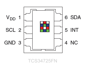
The shield also has a light sensor, meant to measure ambient brightness. One can use this to make the display’s brightness match the room. The sensor is connected via I2C, since neither the Arduino nor the Olimexino-5510 have I2C exposed on the pins I will have to do a software solution for this. The TCS34725FN sensor is also capable of measuring RGB color; I’m sure something fun can be accomplished using that.

TCS34725FN

Olimexino-5510

The olimexino-5510 chip contains an MSP430F5510. The board has USB capabilities(I’ll make use in that in order to sync the clock with the computer).

Parts

D1
L1
U1-power
U2-sensor
Q1-pmosfet
Q2-npn
2x Male Header Pins(40 pos)
C1, C10, C11, C13, C15, C17 6x 100nF
C4, C5, C7, C8, C9, C12, C14, C16, C18 9x 10uF
C2 12pF
C3 15nF
C6 4.7uF
R1 30.9k 1%
R2 10.0k 1%
R3 82.5k
R4 2.8k
R5,R6 2x 1k
R7,R8 2x 4.7k
Charging Resistor for olimexino 2k
18x WS2812
Olimexino-5510
6600mAh battery


Open Source 3.2” TFT Smart Display

smart_display_1

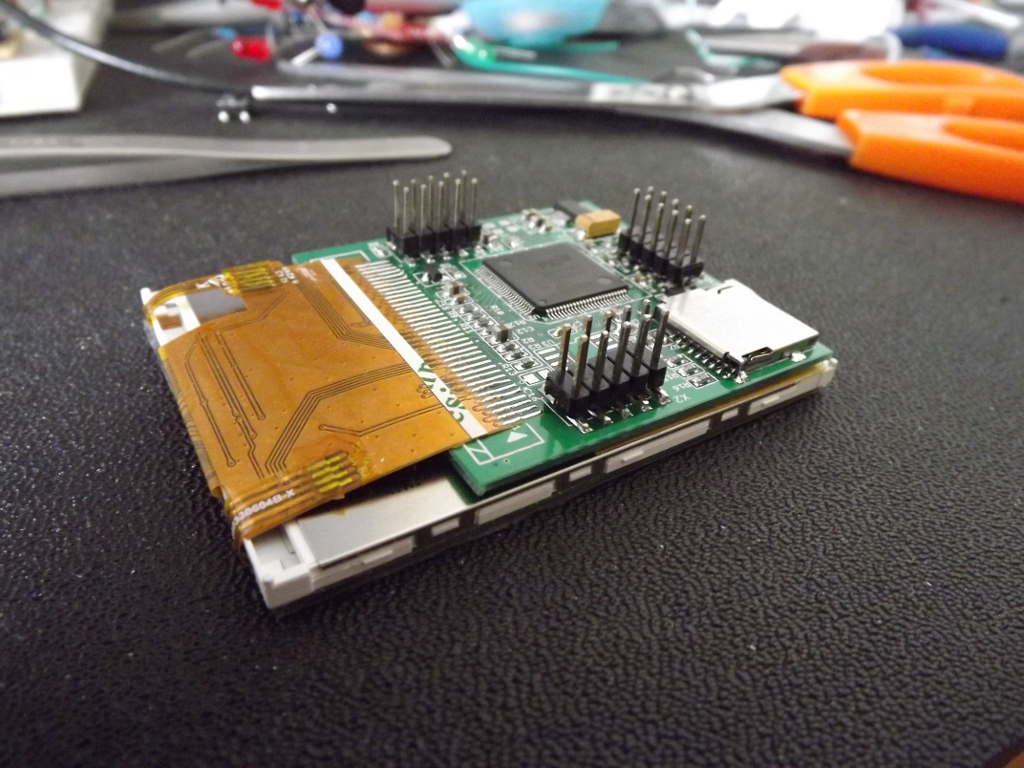
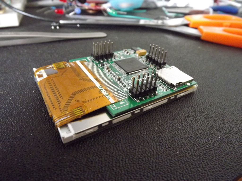
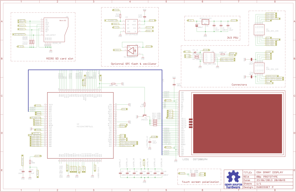
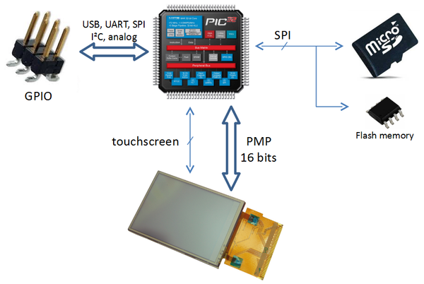
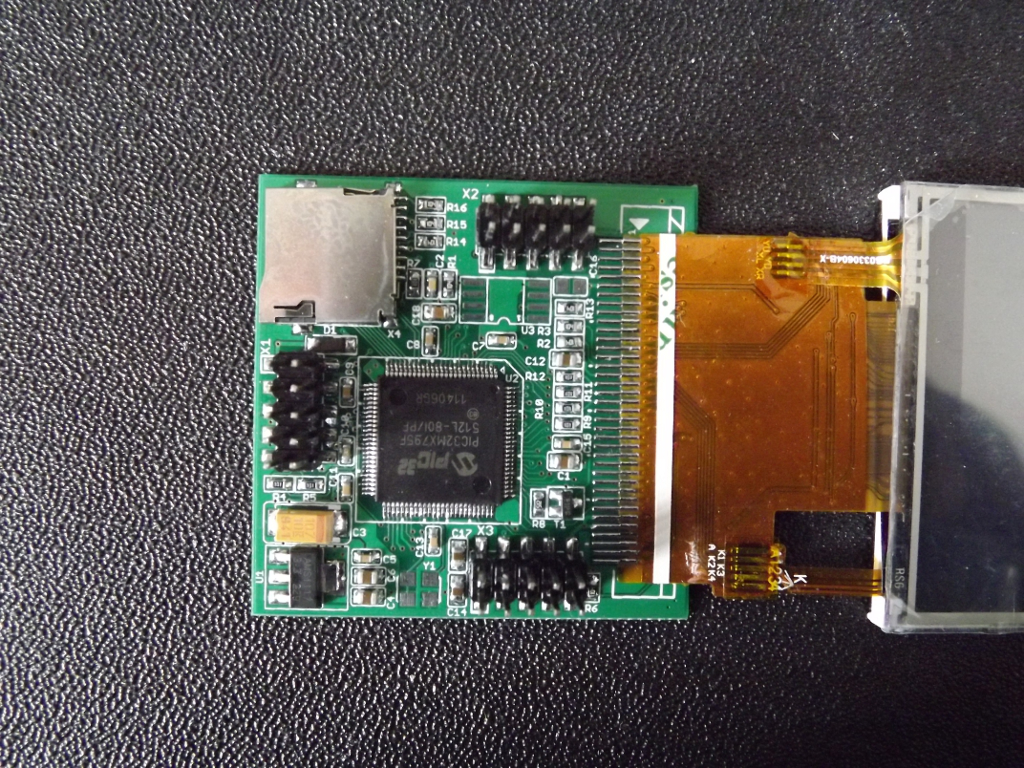
This project is an open source 3.2″ Smart TFT display board. The board is based on a PIC32 and a 3.2′ TFT with touchscreen (ILI9320 controller, using 16bits PMP). The software has two main parts. One that produces the 2D functions and a GUI with various widgets (buttons, check boxes, sliders etc).

Schematic

smart_display_schematics

Description

A new version of 3.2″ TFT Smart Display project can be found here

In the beginning, I just wanted to play with these cheap TFT screens available on eBay (displaying some pictures & text, nothing more); step by step, I finally designed a PCB and a built a consequent software with many 2D basic functions and even a small GUI.

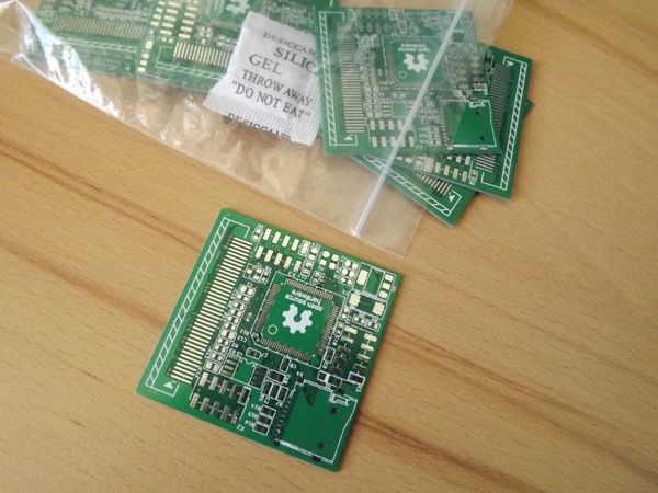
The board is based on a PIC32 and a 3.2′ TFT with touchscreen (ILI9320 controller, using 16bits PMP). The PCB is 4.9 x 4.9 cm, 2 layers (=> $15 / 10 units at seeedfusion).

About the software: I’ve first tried to use some parts of code provided by Microchip, but their library looks like quite complex from my point of view (some files with more than 5k lines, with too much #ifdef…. ><“). As a result, I rewrote a new software, from scratch; this software is composed of 2 main parts:

– P2D: 2D functions (drawing a line, put some texts & sprites, draw filled polygons, memory buffering…)

– GUI: small GUI with some basic widgets (buttons, checkbox, graph, …). Each widget has generic attributes (disabled, notified, focused, …), can be grouped and linked to signals (e.g. emit a signal when the widget is pressed)

The project is under OSHW / GPL3.

arch

PCB

smart_display_2

reception_pcb

Demo Videos

Digital & Binary clock with thermometer & hygrometer

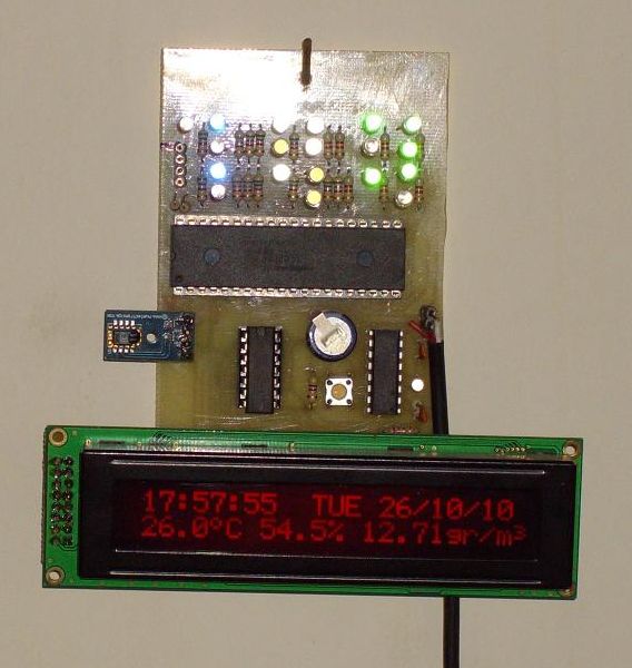
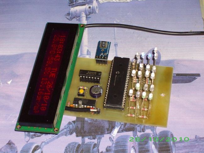
Photo_1

Here we have a clock. It’s not “another clock”. It has digital and binary output. It also has a thermometer and a hygrometer. It’s not “another thermo-hygrometer”. It display’s absolutely humidity (gr/m3) also.

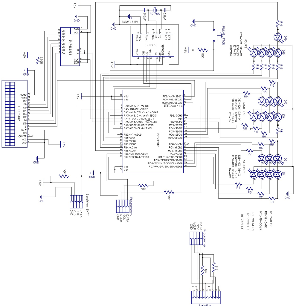
Schematic

Schematic

MCU

I build it around Microchip PIC16F917, with internal Oscillator at 4MHz. I also build a serial port programmer, so I can programming it on-line, using the DL4YHF WinPic.

Clock

I use a RealTimeClock Maxim DS1305. The RTC backup power is a supercapacitor (0,22F). I test  it for 4 weeks, works fine. For this reason it don’t have the capability to change the time, but you can do small-corrections. Once you push the button, the seconds change to 30, with no effect to minutes, hours etc. The routine is in lines 1878-1887 “sec30“.

You set the time when you program the PIC. You have to program two times. The first time without line 91 (goto  rdtime). The routines setDS andsettime is execute.

SetDS is setting RTC’s control and trickle charger registers. In the settime routine, you set the time. After this, you add line 91 (goto  rdtime) and you reprogram it. Now the routines do not execute. RTC can keep the setting and time at least for 28 days. The routines DST3 and DST10 are for DaySavingTime. The check register is flag, 1. The checking routine is in lines 434-460. In the last Sunday of March, the 02:00 o’clock became 03:00 o’clock. In the last Sunday of October, the 02:00 o’clock became 01:00 o’clock. I set the RTC for 12H mode, leds for 12H and display for 24H.

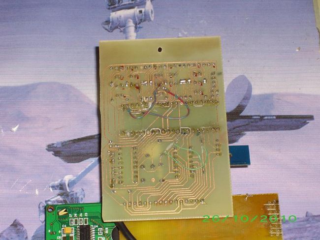
Photo_2

Temperature – Humidity

I use a digital humidity and temperature sensor Sensirion SHT11.
I bought it in a PCB, with the pull-up resistor and decoupled capacitor ready in place.
Measurements make every 10 seconds.
At 00, 20 and 40 seconds it measures the temperature and calculate the temperature and Absolutely Humidity (“gr/m3” grams at cubic meter of air).
At 10, 30 and 50 second it measures the humidity and calculate the Relative Humidity (%).
The check register is flag, 0. The checking routine is in lines 464-475.
The measure temperature routine is in lines 477-514 “measTEMP” and lines 625-714 “measure“.
The calculate temperature routine is in lines 1793-1820 “calcTEMP“.
The measure Relative humidity routine is in lines 560-590 “measRH” and lines 625-714 “measure“.
The measure Absolute humidity routine is in lines 515-555 “measAH“.
The calculate Relative humidity routine is in lines 717-1470 “calcRH“.
The calculate Absolute humidity routine is in lines 1473-1728 “calcAH“.

Photo_3 (1)

LCD display

I use a Chinese display 2line, 24row, with backlight. I drive it with a sift register T.I. 74164.

LED display

I use bright leds. 7 green with 8,2K resistors for seconds, 7 white with 5,6K resistors for minutes and 5 blue with 560R resistors for hours. The maximum current for leds is about 17mA, so I don’t have to drive them with transistors.

MultiKey – One Wire Keypad

Photo_1

Introduction

This is a simple and easy to make serial keypad. The microcontroller will output the number of the push button pressed.

This project can be used for many different purposes. Probably the most used application would be to interface to any electronic project that requires a keypad. There are several ready made keypads on the market, but those work with matrix connections and require 7 pins for a 12 button pad. For new programmers, matrix keypads can be a bit tricky to program.

My circuit can use from 4 up to 12 push buttons with only one wire connection ( plus ground pin ) making possible to use a small microcontroller like an 8 pin to use this keypad. It’s also built in a setup mode where it’s possible to change the key output rate. This setting is saved in the microcontroller’s memory.

Another use for this is to, for example, connect to the computer and use it to control applications or even games.

Using any RS232 to keyboard software it’s possible to assign the input signals and convert them to keystrokes.

Schematic

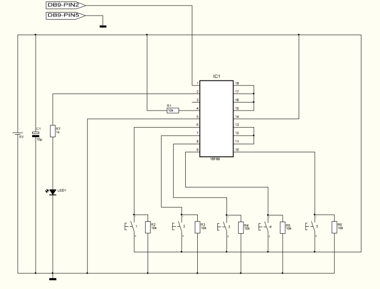
The schematic shown bellow is for the 5 button version.

Schematic

Notice that pins 11,12,13,15,16,17 and 18 are connected to ground. For each button added just remove the ground connection and connect the pin to a push button and add the resistor the same way as the first buttons.

Parts List

R1                   10K ohms resistor
R2                   10K ohms resistor
R3                   10K ohms resistor
R4                   10K ohms resistor
R5                   10K ohms resistor
R6                   10K ohms resistor
R7                   1K ohms resistor
C1                   10uF capacitor
Led1                SMD green or red led
IC1                  16F88 microcontroller from Microchip
S1                    Push button
S2                    Push button
S3                    Push button
S4                    Push button
S5                    Push button

 
Others:
 
Box
DB9 connector
PCB
Hex program for the microcontroller
 
For 12 push button version:
 
R8                   10K ohms resistor
R9                   10K ohms resistor
R10                 10K ohms resistor
R11                 10K ohms resistor
R12                 10K ohms resistor
R13                 10K ohms resistor
R14                 10K ohms resistor
S6                    Push button
S7                    Push button
S8                    Push button
S9                    Push button
S10                  Push button
S11                  Push button
S12                  Push button

How it works

For the first time I recommend to connect it to any pc and using the terminal program select 9600 Baud, no parity, 8 for byte size and 1 stop bit. These are the settings for both pc terminal or receiver microcontroller. To enter the Setup mode the S4 button should be pressed and held when turning the power on. The led starts to flash and S1 is used to increase the rate while S2 is used to decrease the rate. The minimum rate is 10ms and the maximum rate is 2550ms. It will increase/decrease 5ms each button press. Pressing and holding S3 will test the setting and will display the rate speed both on led and RS232. Button S4 will save the setting into microcontroller’s memory, exit the setup mode and enter the normal mode. In normal mode, when pressing one of the buttons it will flash the led and output the corresponding button number via RS232.

Hex Programm

The Hex program named Multikey must be saved in the device’s memory ( 16F88 )

Testing

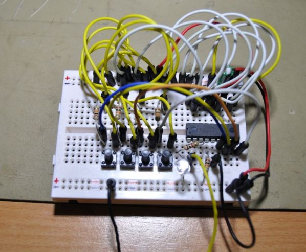
I’ve assembled the minimum button setup ( 4 buttons ) on a breadboard and connected directly to my PC RS232 port. I didn’t use any level converter, such a max232, because it normally works very well without it. In some cases it’s required to have the level converter. Turned the power on and pushed the buttons. The output was too fast so I turned the power off. I turned on the power again but this time i entered into setup mode. Increased the rate to 200ms and saved the setting. Tested again and now I get a good response.

MCS08DZ60 Evaluation Board

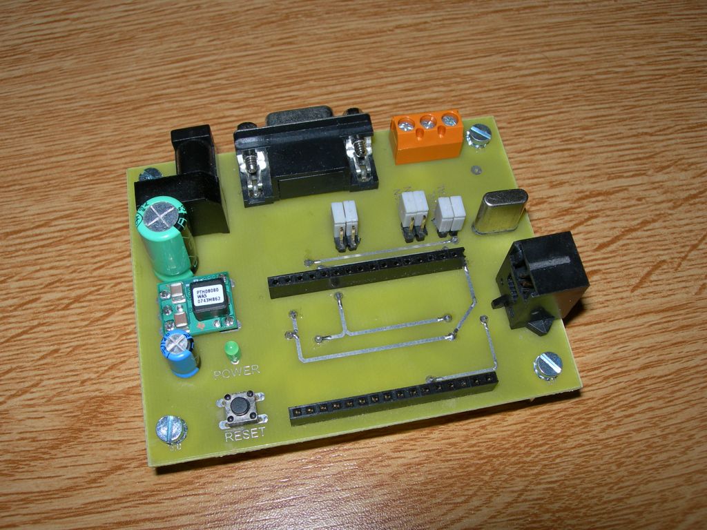
Photo_1

Introduction

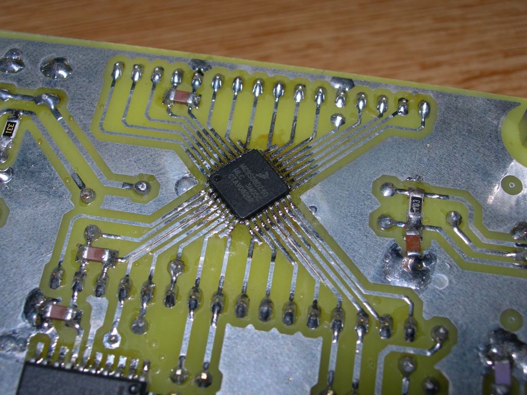
The board shown in this article is build around a recent microcontroller from Freescale. It has some interesting features presented below, and is initially developed to learn with the CAN bus. It is an easy to build board particularly adapted for beginners.

The Microcontoller

The microcontroller used is the 68HCS08DZ60, from Freescale, and coming with an LQFP32 package. It is initially a microcontroller designed for automotive applications. It has some very interesting features:

  • 60Ko of Flash memory;
  • 4Ko of RAM;
  • 2Ko of EEPROM ;
  • Integrated CAN bus controller;
  • Integrated SCI controller with LIN capability;
  • Integrated I2C controller;
  • Integrated SPI controller;
  • Analog inputs, with a resolution of 12bits;
  • Timers which can generated PWM signals;
  • And more…

The Board

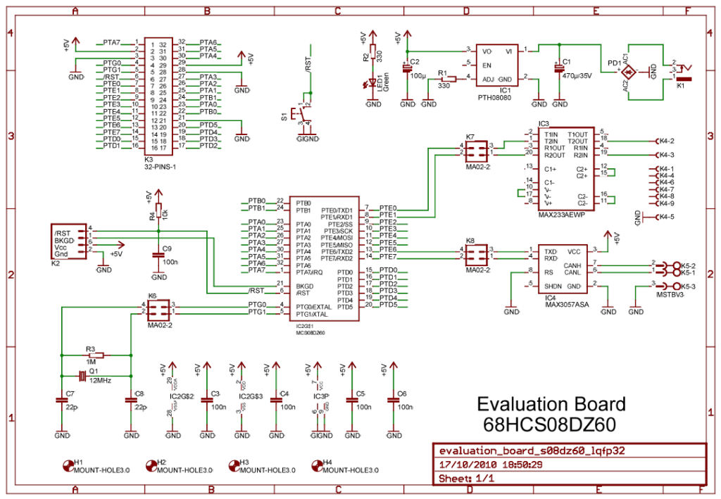
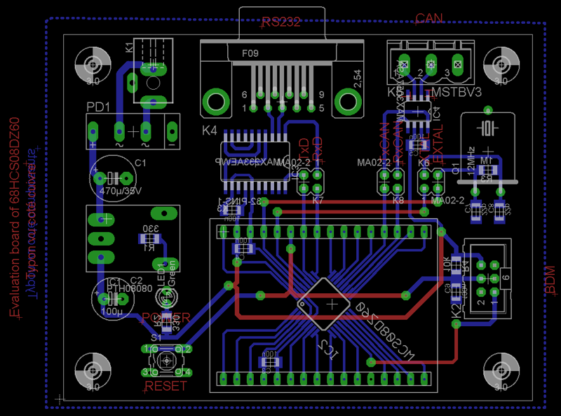
Please, see the schematic of the board.

Schematic

The board has been initially developed to learn with CAN, so a CAN transceiver is available (IC4). The CAN transceiver comes from Maxim, but some other manufacturers provide some compatible CAN transceivers which can be used. An RS232 transceiver is also mounted on the board to get an RS232 interface, to connect the board to a computer. It could be used for debug purpose for example. Both transceivers are connected to the microcontroller throw jumpers, so it is possible to disconnect the transceivers and use the pin of the microcontroller as classical GPIOs. The other parts of the schematic are not so special, we can found:

  • The power supply, build around a DC/DC converter (IC1 ; a classical linear voltage regulator like 7805 can also be used without any modification of the PCB);
  • A LED to indicate that the board is supplied (LED1);
  • A switch connected on the RESET pin of the microcontroller (S1);
  • The crystal (Q1). Note that the crystal is connected to the microcontroller throw jumpers: the device can work with an internal clock and in this case, the pins are available as classical GPIOs.
  • Finally, there are some decoupling capacitors for all integrated circuits.

The power of the board will be applied on K1. Any power supplied can be used if it provided between  8 to 12 Volts AC or DC. K2 will be used to connect the programming cable, and K3 gives an access to all the pins of the microcontroller. K3 is build with two arrays of connectors to plug a module on the evaluation board (see photo #1).

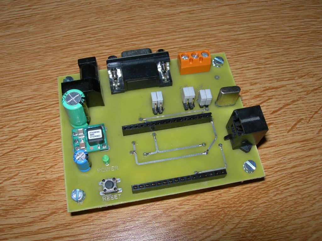
Photo_2

Programming the microcontroller

To program the microcontroller, you will need a programming cable for Freescale HCS08 devices and you will have to download CodeWarrior for Microcontrollers from Freescale Web Site. Open source debugging cable and examples to begin with this board (CAN, 1-Wire, I²C, EEPROM …) are shown on my Web Site: http://myfreescalewebpage.free.fr

PCB

Conclusion

This small evaluation board is easy to build and will enable lots of experimentations. I have make two boards in order to create a small network throw the CAN interface. Of course this board is also interesting if you want to develop application around I²C, SPI, SCI… Remember that the peripherals available on the 8bits devices from Freescale are the same than on the 16 and 32bits devices, like the Coldfire for example. It is why this board is maybe the best way to start programming and learning with Freescale devices.

Microcontroller Clapper Switch

photo_1

Introduction

I always thought the clapper so cool. For those who are lazy like me, turn on or off the bedroom light without getting out of bed, simple clap your hands is amazing. Thinking about it I projected one for me. Several projects of clappers can be found on the Internet, and most of them do not use microcontroller.

I chose to use a micro planning future updates, such as turn on or off the light with 2 claps, the TV with 3 claps, DVD player with 4 and so on. Another update can be a time to turn off the device automatically.

Hardware

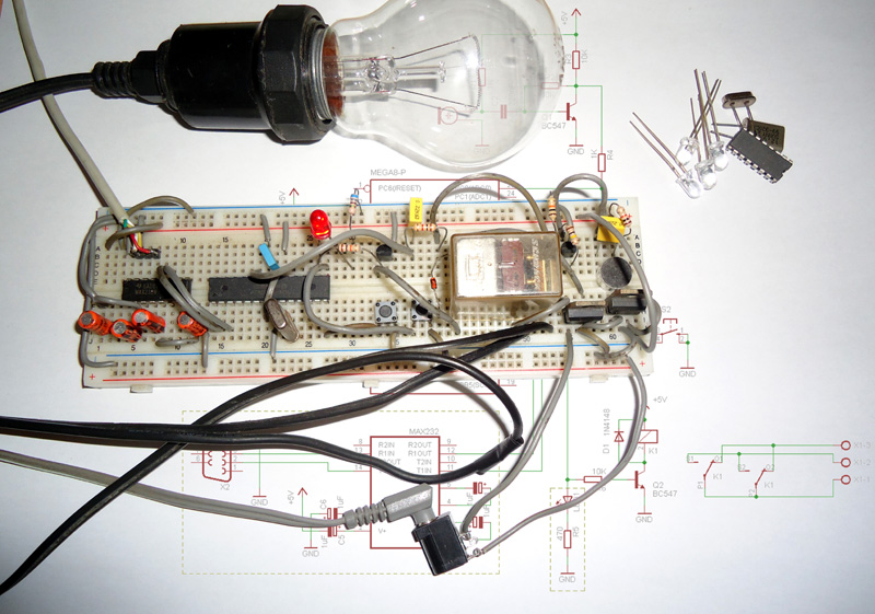
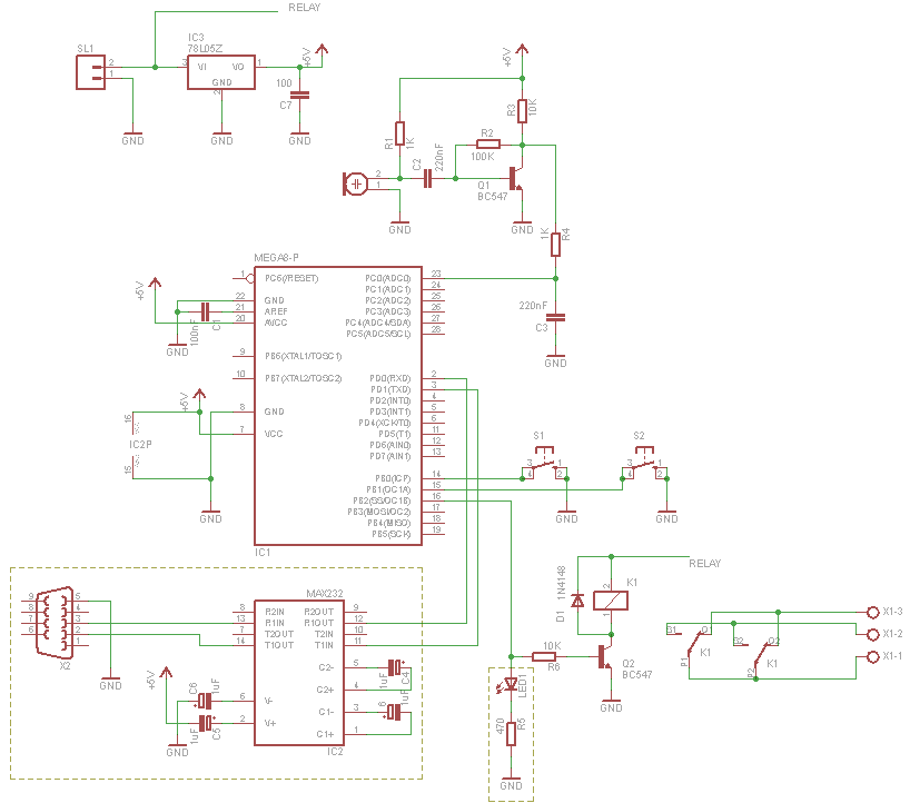
The hardware is very simple, just a microcontroller, a electret mic, a relay and some discrete components. The microcontroller is the brain of the project, I used a atmega8 because it was the only I had available.

The signal is captured by the mic and amplified by the transistor (BC548), this signal run through a lowpass filter that remove the high frequencies and go to mega8 ADC. To keep the circuit simple, only one transistor is used on signal amplification. Two buttons are used to up or down the sensibility of the signal. You can see the complete schematic below. The components on dotted line are optional.

The circuit can be powered with 7 ~ 12V and the relay must be for that voltage.

Schematic

Software

The software was written in C using AVR Studio and WinAVR library. The ADC is read constantly, and the returned value is compared with a variable. This variable can be changed if the user press the button S1 or S2.

So, the user can increase or decrease the intensity of the signal necessary to trigger the circuit. If the value of the ADC is less than the variable, nothing happens, otherwise the timer0 is activated and begins counting. At each timer overflow, a variable called timer is incremented.

The value of variable timer is compared with three constants, burst_time, ready_time and time_out. If the value of the variable is equal to the constant burst_time the value of global variable burst become 1. If the value of timer is equal the constant ready_time the value of variable burst becomes 0 and variable ready becomes 1. If value of timer is equal time_out all the variables become equal to 0.

When another clap is detected, if burst = 1 then the microcontroller clear all variables and start the loop again. If burst = 0 and ready = 1 the output is toggled.

The relay only close when the time between a clap and another is approximately correct, thus reducing the chances of the light turn on or off accidentally.

The flowchart below help understand the software.

flow

USART

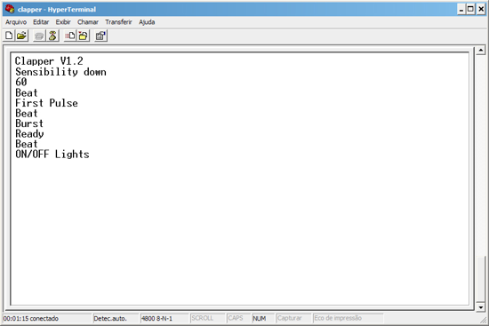
The USART is used to debug the code and help understand how the software works.

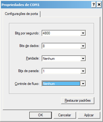
clapper_config_hyperterm

The hyper terminal config

clapper_hyperterm

Clapper working!

Arduino Solar Day Night Controller

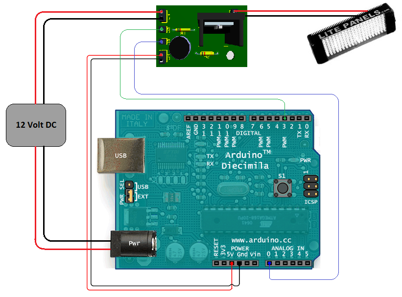
Complete

Introduction

This is an Arduino controlled light sensing switching unit. Its main use is to control solar lights to turn on when it is dark outside, but it can work in many more applications. This guide will walk you through every aspect of the building process. Prior knowledge of the Arduino unit is not necessary since the code and schematic have been supplied for you. This project would be fairly complex to build without an Arduino; it is a good example of how a microcontroller can make a circuit far less complex, with less hardware trial and error.

Specs

  • Input Voltage Range: 7 to 18 Volts DC
  • Switching Power: 3 Amps*
  • Light Range: Variable, Very Bright to Dark

*Adding a Relay can greatly increase the switching amperage.

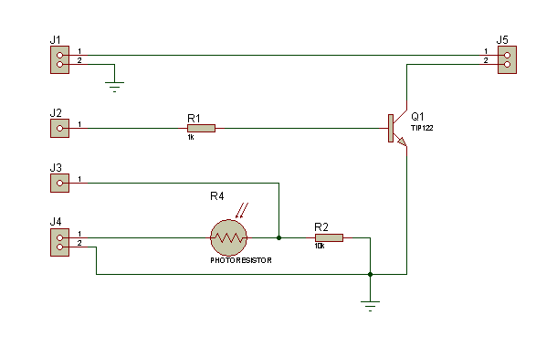
Shematic

Explanation

This project has three main sections, the Arduino unit, the software, and the circuit.

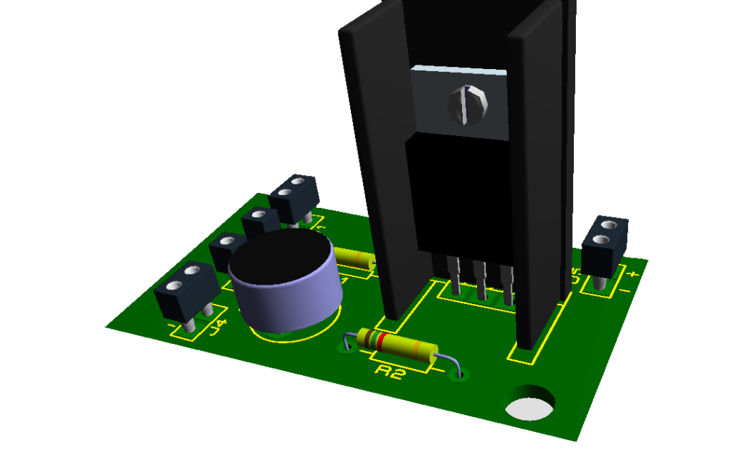
PCB_3D_Side

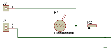
The Circuit is composed of two sections, the light sensing and the power switching. The light sensing part consists of a photo-resistor R4, connected like a voltage divider to R2. Since the resistance of the photo-resistor changes depending on the amount of light that is shining on it, the voltage divider’svoltage ratio changes depending on the amount of light present. The voltage going through this part of the circuit is 5 volts dc, supplied from the Arduino board to J4 of the circuit. So the voltage divider is dividing the voltage between the maximum 5 volts, to the minimum 0 volts. The Arduino senses this voltage on its “Analog Pin 0” that connects to J3 on the circuit. This is called “analogRead,” it divides the 0 to 5 volts by 1024 (10 bits, or 2^10) so it can sense a change in voltage as small as .0048 of a volt.

Shematic_1

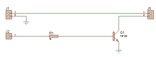
The power switching section of the circuit is quite simple; it uses a NPN switching transistor Q1, that is digitally controlled by the Arduino board from ‘Digital Pin 3’ connected to the circuit through J2. It switches the negative leg of the supply voltage from J1. J5 is where a low voltage light or anything you want turned on and off is connected.

Shematic_2

here is no R3 on the schematic, my apology I labeled the photo-resistor R4 on accident, sorry. I included two different PCB bottom copper designs, one has a ground plane and the other does not. Use whichever you prefer. 

I won’t go into the parts of the Arduino, mainly because it is already a well-documented unit. The picture at the top should make it fairly obvious to see how it is connected. The main thing to look out for is the PWR SEL jumper between the USB and the PWR connector, needs to be switched to EXT, if it is not powered from the USB. If there is something you don’t understand, you will get much more help from their homepage:http://arduino.cc/en/Guide/HomePage

The software is in a zipped folder called ‘Code.zip‘ and it works like this:

flow

Parts List

Quantity Reference Description
1 R1 1k Ohm 1/8 Watt Resistor
1 R2 10k Ohm 1/8 Watt Resistor
1 R4 Photo-Resistors (276-1657)
1 Q1 TIP122 Darlington Transistor
1 . TO-220 Heat Sink
1 . Arduino

Helpful Links

LED UV exposure box

UVbox12


Introduction

I have been using the toner transfer method for about 9 years with great results. Occasionally I would need a board with finer traces and I would use UV method. My exposure setup allowed only a single sided board to be made and it was composed of a 30cm UV tube, some holders, a table, board and film. Exposure time was rather long as the tube was far away from the board.

A few months ago I was looking for some LEDs at one of my suppliers and found that the also had UV LEDs. My mind went directly to upgrading my not so great setup, so I began looking on the internet for info. It turns out some other people have done it, and this instructable confirmed it was really possible. A LED UV box has a clear advantage over a tube one: it can be made in any size, depending on the needs.

I bought 25 LEDs and began to experiment. This way I was able to find a compromise between LED density (spacing), distance between LEDs and board and cost. I wanted something compact, I don’t make large PCBs and those 30cm tubes were not right for this job.

Note: Don’t look directly into the UV LEDs. It may harm your eyes.

The LEDs

The LEDs are OSSV53E1A from OptoSupply and they have an 140° angle. This means that the first plane with uniform density can be obtained at a shorter distance from the LED, for a given spacing between LEDs which means smaller height for the board. Their peak wavelength is 405nm, which is higher than recommended by the boards’ manufacturer. Results showed they emit sufficient UV light in the responsive spectrum of the photo resist to allow for a perfect exposure.

I wanted to use a common voltage so 3 LEDs in series with a 91Ω resistor are connected to 12V to ensure a 20mA current.
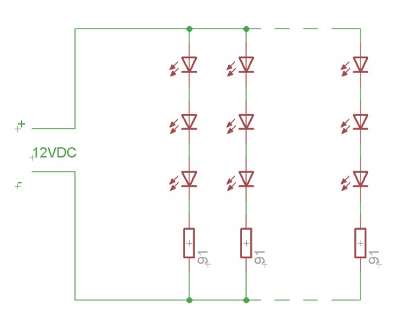
array_schematic

The final setup will contain a LM317 for stabilizing as I don’t plan on using my variable regulated supply all the time. There is another reason for this, due to the non linear nature of the LEDs, varying 12V with +/-5% creates much larger current variations which influences the required time. Putting a regulator on the box simply allows more flexibility in choosing the power supply. 

On the bottom board I have added red LEDs. These LEDs help me align the top and bottom films. I have used low brightness, cheap, matte LEDs as I have to look into them when aligning the films. Connection is similar, 3 LEDs in series with a 220Ω resistor, except for the last row which contains 2 LEDs and a 330Ω resistor. These are not really necessary, aligning the films can be done in a dim ambient light.

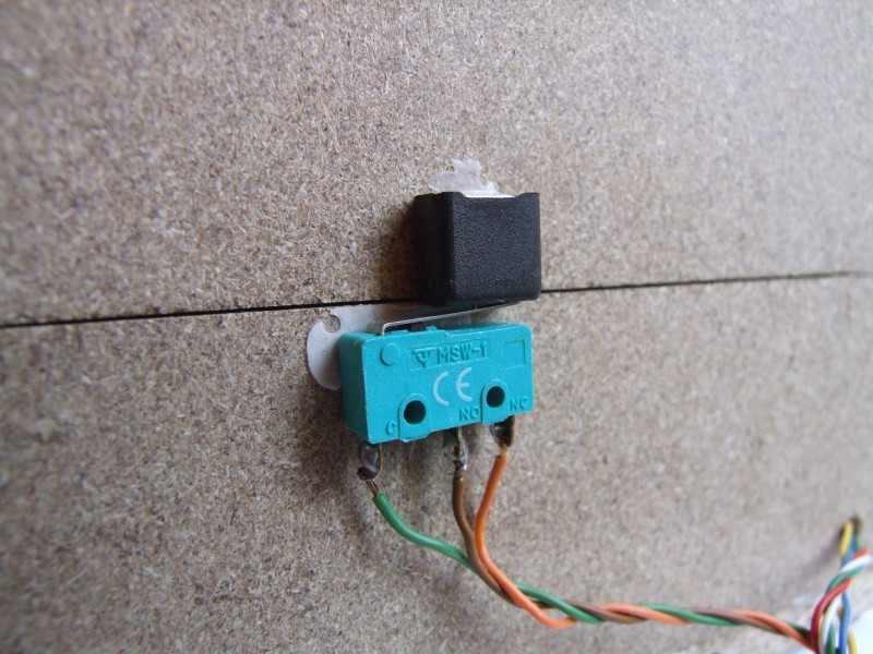
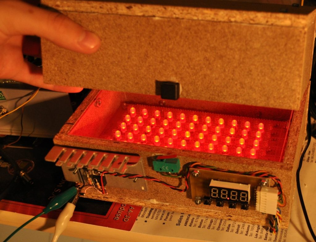
For safety reasons and extra functionality I added a switch to turn off the UV light when the box opens, turn on the red light and stop the timer. This makes the box more high tech and gives it a professional behavior.

LED spacing

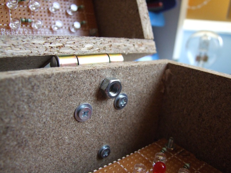
I used nuts glued on the interior walls of the box to hold the bottom 4 mm thick plexiglas panel. The choice was simply of what was easily available: nuts.  Don’t use normal glass as it blocks ultraviolet light. There is no top panel mounted, because it is part of the aligning procedure: I put the first film on the bottom, then the board and the second film is taped to a smaller piece of plexiglas. Aligning means aligning the smaller piece of the plexiglas so that the two layers overlap perfectly. Having the film attached to it makes it easier. Extra markings outside the board help this (ghost vias). Part two should contain a more detailed tutorial on making double sided boards. 

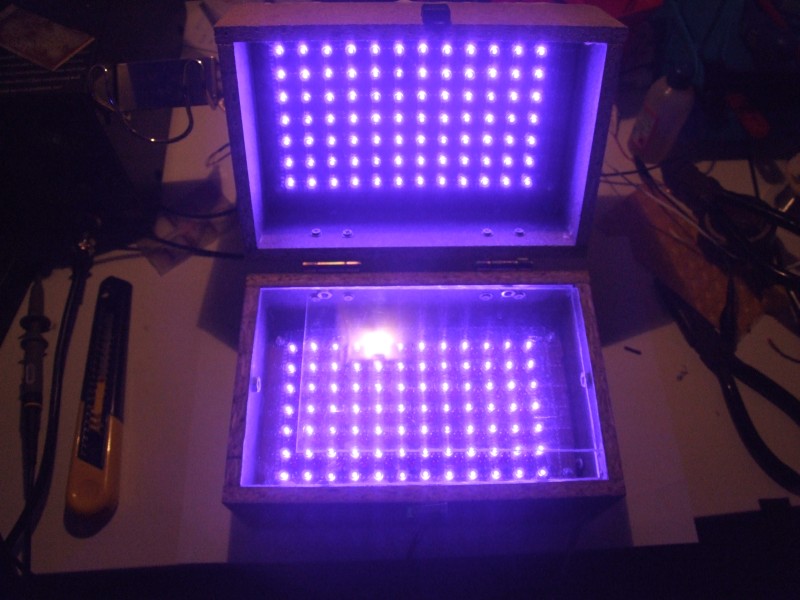
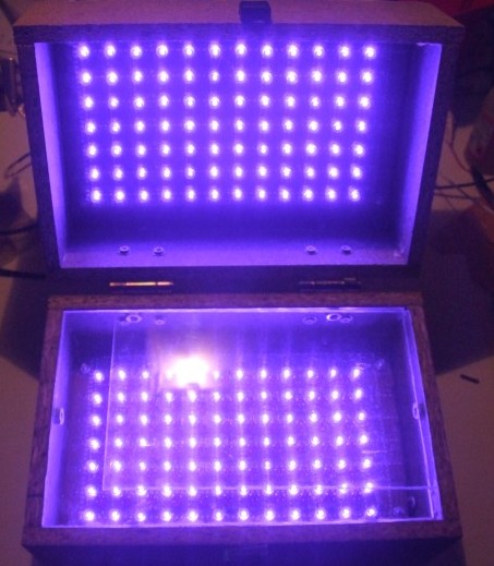
The final assembly allows an area of about 10x15cm of board size, with the interior dimensions of the box being 18cm long, 11cm wide and 5.5cm deep for each of the two halves. Exterior dimensions will depend on the thickness of the material used. Each board contains 7×12 UV LEDs, with 3 and respectively 4 holes between them( the actual spacing between the center of the LEDs is the same). The distance between the top of the LEDs and the board is 3.5cm, including the 4mm plexiglas panel. Check out the detail below to see the LED arrangement on a normal 0.1″ or 1.27 spaced board:
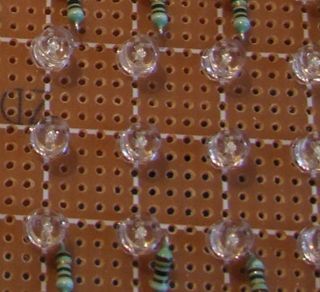
led_distance_detail

Exposure

Exposure results:  I tested with a small board from 2 minutes up to 8 minutes. Starting with the minimum of 2 minutes proved not to be the best idea, but my long exposure time old setup made me choose this value.
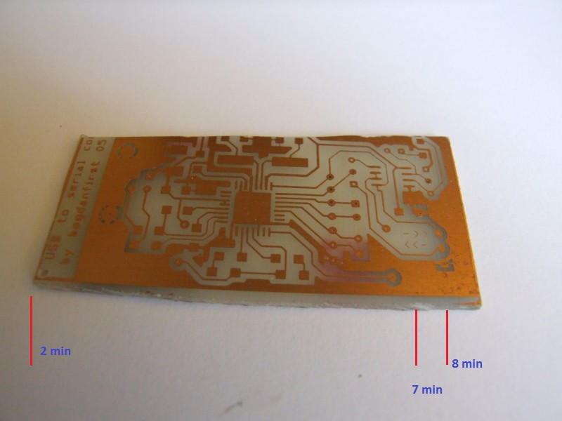
timed

What you can see in the picture above, from 2 to 7 minutes exposure if perfect. At 7 minutes some over exposure starts to show up, only in large copper areas, due to the fact that the film was printed with a laser printer. This result is very different from what I have obtained when using a fluorescent tube: below 12 minutes it was clearly underexposed and above 14 it was clearly overexposed, leaving only a small interval where it was right. 

So far I have made 4 boards with 2 minute exposure and they came out perfect. When free time will be available I will investigate what the results are for less than 2 minute exposure. As any time between 2 and 7 minutes seems to work, there is no immediate need for a timer. Still, part two should contain a basic circuit for this.

Gallery

The finished panels:
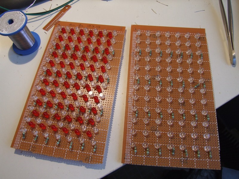
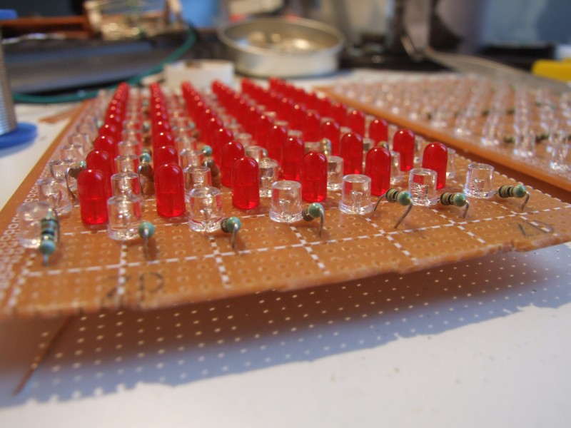
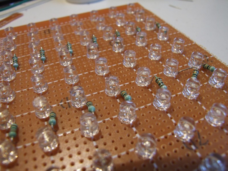
UVbox1

UVbox2

UVbox3

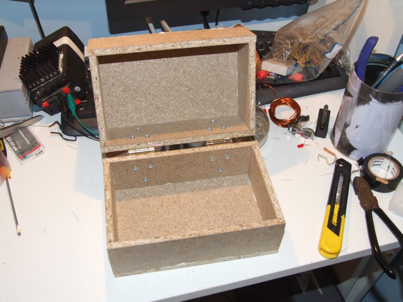
The box:

UVbox4

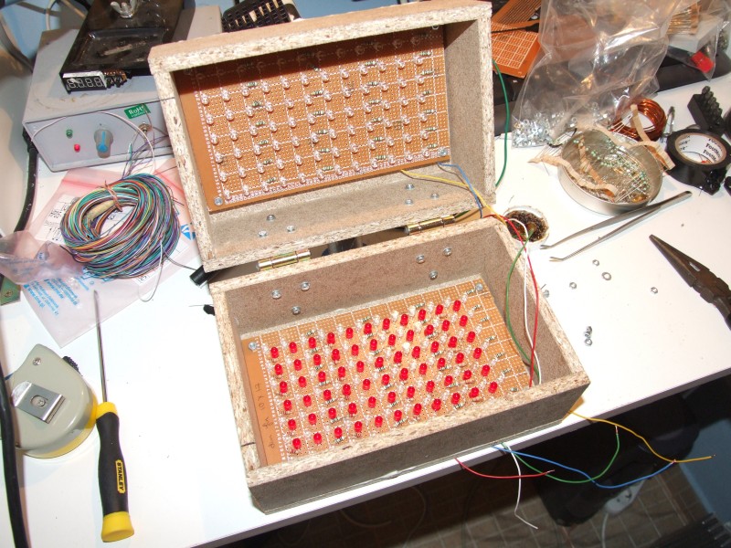
Panels installed:

UVbox11

Bottom plexiglas panel installed and a nut:
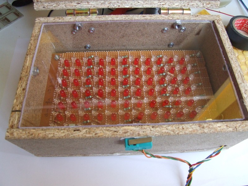
UVbox5

UVbox8

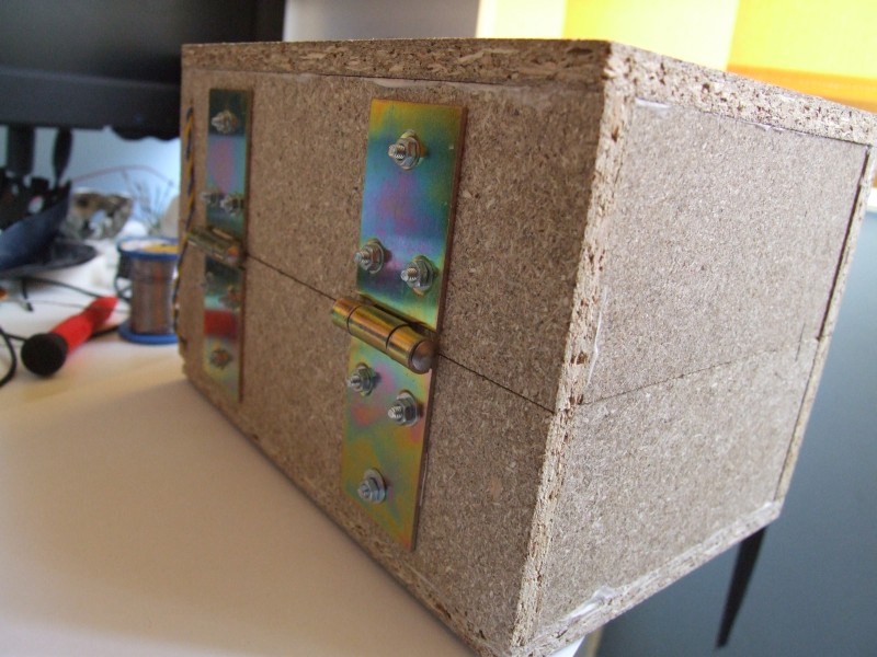
The back:

UVbox7

The safety switch:

UVbox6

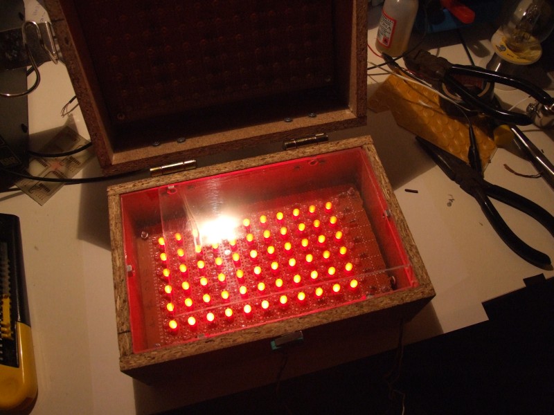
RED on:

UVbox10

UV on (switch is not used):

UVbox9

Build your own

To build your own you first must decide what the required size is for you. With my setup, boards up to 10 x 15 cm may be exposed. For this, you will need the following materials:

  • 168 UV LEDs,  OSSV53E1A;
  • 56 91 ohm 1% 0.25W resistors(5% is also ok);
  • 66 red diffused LEDs;
  • 18 220 ohm resistors for red LEDs;
  • 6 330 ohm resistors for red LEDs;
  • 2 prototype boards, 13 x 25 were the smallest size I found that fitted;
  • 1 switch for the lid capable of 1.5A minimum;
  • 2 hinges;
  • 1 box;
  • misc: screws, nuts, glue etc.

The box may be made of your choice of material. I’ve built it out of two identical halves, with interior dimensions 18 x 11 x 5.5cm each. The material is 8mm thick OSB, for which you will require the following parts:

  • 4 11 x 5.5cm pieces;
  • 4 19.6 x 5.5cm  pieces;
  • 2 19.6×12.6cm pieces.

The timer

Continuing the development of my UV exposure box I have designed and built a countdown timer.

There are a few others out there for the same purpose, but I wanted to add some more features to make things better.

As I have mentioned in the previous post, safety was a big concern for me so I added a switch that should prevent turning on the UV LEDs when the lid is open.  Of course, this is not enough, so the switch has to work along with the timer ensuring that everything goes smoothly.

The key features that I wanted:

  • Exact time display
  • Adjustable time, 10 second resolution
  • Start/pause function
  • Automatic pause and UV LED turn off when the lid is open
  • Some predefined available values for easy access.

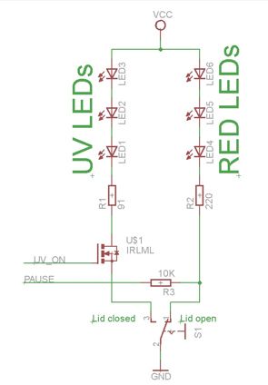
Implementing the safety measures is easy, as the switch on the box could be made to connect either the RED or the UV LEDs.  The timer needs to control the UV LEDs, so I have used a MOS transistor. It also needs to know the state of the box lid. I have built a circuit that can achieve all this. The concept schematic can be seen below:
timer_principle_th

The schematic shows, symbolically, the red and UV LED arrays through the basic cell that is repeated on the panels: a series of three LEDs and a resistor. As you can see, there is no way to turn on the UV light when the lid is open, even if such a command would come from the microcontroller. The microcontroller can turn the UV light on via the MOS transistor only when the lid is closed. This is controlled through software too. In order to sense whether the lid is open or not, the microcontroller monitors the state of the cathode of the red LED array. When the lid is open, this is shorted to ground and the micro sees a low logic level. When the lid is open the red LEDs will conduct current and force the microcontroller to see a high. This current is small, limited by the 10K resistor and therefore the LEDs do not appear to be on. I could have chosen to leave the red LEDs on all the time as this does not influence the functionality of the exposure box, but it adds extra consumption and more heat needs to be dissipated by the lower panel.

Although it is not totally justified, I decided to go the full effort and make this timer with a display. There could be many more ways to do this starting from a simple 555 circuit. I wanted the circuit to be a challenge for the box itself, so small SMD parts are used wherever possible.

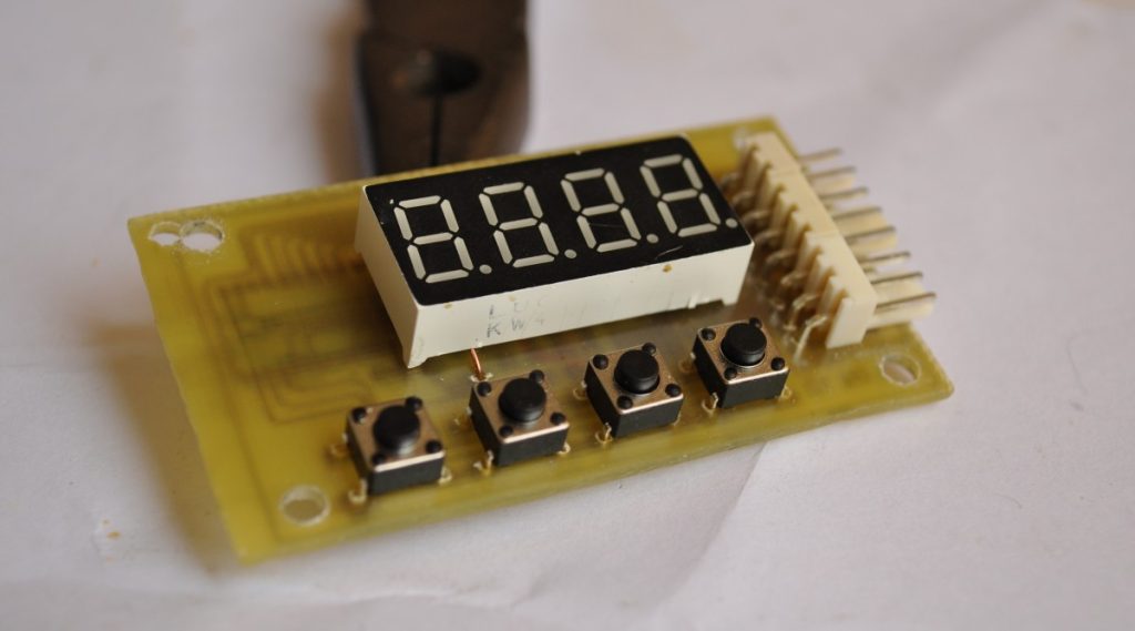
The display is a KW4-361ASB from Luckylight. It is small, 9mm digit height and has 4 multiplexed digits. There were two basic criteria for selecting this particular part, first I wanted it to be small and efficient so that a small current is enough for a bright display and second I wanted it to be multiplexed as this simplifies board layout.

I choose an ATTiny2313 microcontroller as it has all the features needed to implement all the tasks: sufficient pin driving capability, a timer, enough pins and memory. It’s got an internal oscillator too, but as I missed it, the tolerance is within 10% which I consider too high for this project. I have later added a crystal on the board but adjusted the starting timer value on my particular circuit to compensate for the internal oscillator deviance. This was easy as I knew that the refresh frequency for the display should be 50Hz, so a frequency meter was all that I needed. I believe that this should not fluctuate and no future compensation will be needed to maintain the error at a small value, maybe less than 2-3%. I do suggest using a quartz crystal, but this is not mandatory, you may use my method or simply accept the maximum 10% tolerance.

To turn on the UV LEDs I have used a TSM2302 MOS transistor which has a capability of 3.6A, more than enough for both the boards. Other transistors may be used, such as IRLML0060TRPBF.

Other than this, there are 4 buttons on the board, a 7805 regulator and connectors. The 4 buttons have the following functions, from left to right: START/STOP the timer, UP – adds 10 more seconds, DOWN – subtracts 10 seconds, MEM – recalls some preset values from the memory.

Because software allows flexibility in connecting the display, I chose to make the connections as easy as possible for the PCB layout, and this is why the schematic is not very straightforward.
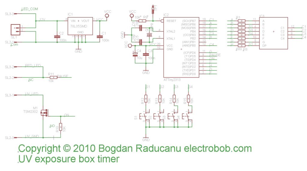
schematic

The connection of the lid switch and LED arrays is shown below:
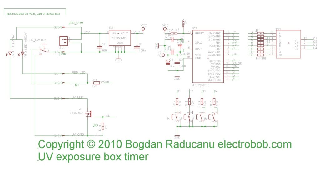
schematic_with_box_connections

Because the box was functional, I decided to make the PCB a challenge for it: Small display, small SMD components. The finished PCB is shown below, the board is very compact and measures less than 6×3.5cm:
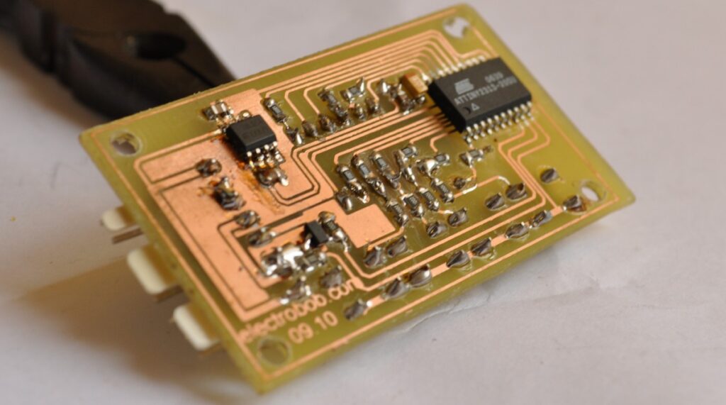
timer_pcb_finished

You may wonder why there is no programming connector. The reasons are two: I wanted to make it as compact as possible and the fact that it is the type of circuit that requires a single programming (For the end user). As all the pins required for programming are connected to the display it is easy to connect a few wires to the programmer, as you can see I did in the picture below:
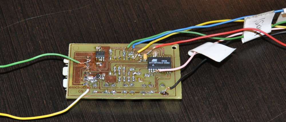
timer_programming

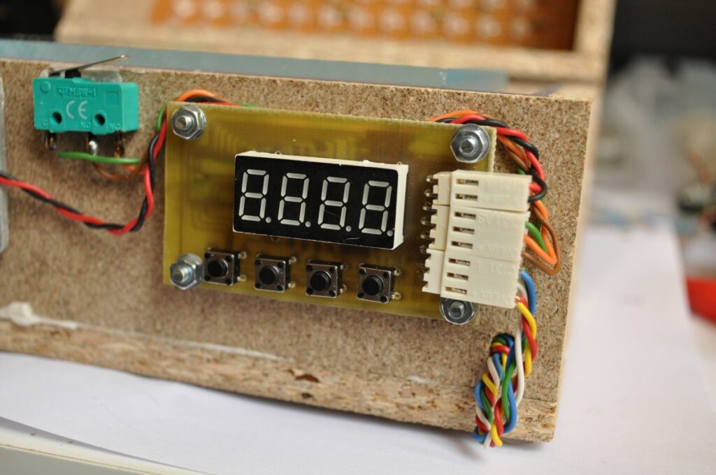
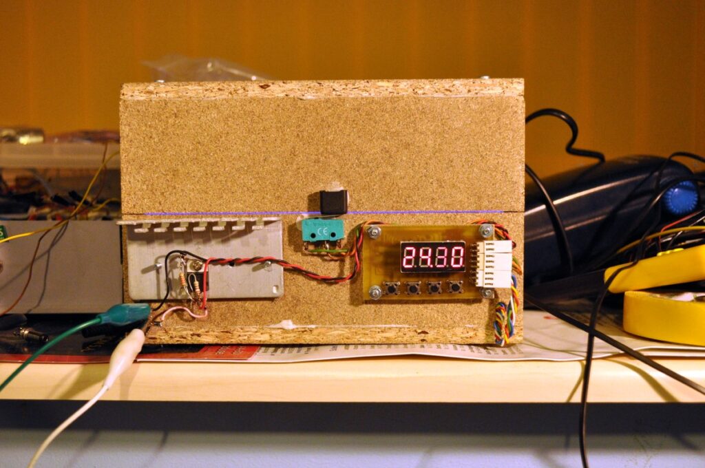
The finished timer:

timer_front

LM317 voltage regulator and heatsink also mounted on the box:
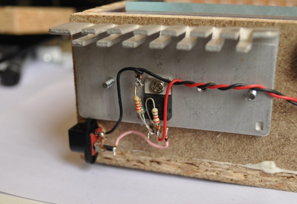
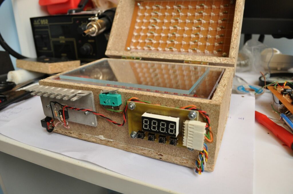
LM317_and_heatsink_mounted

I’ve used 2 nuts on each of the mounting screws between the heatsink and the box to ensure good air circulation:
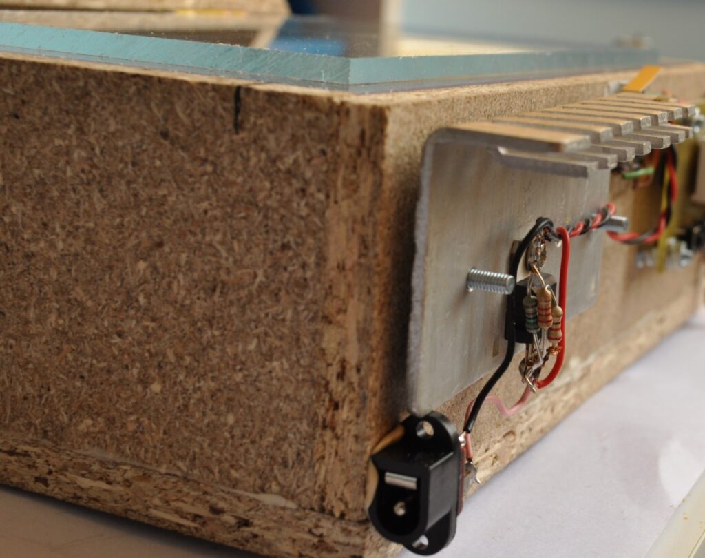
heatsink_spacing

And, of course, a 3A protection diode, just in case:
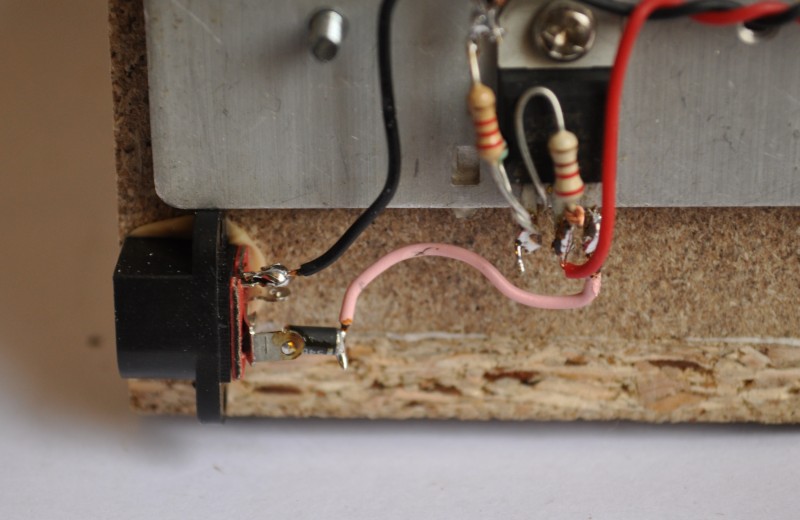
protection_diode

The mounted timer:

timer_mounted

The final result:

finished_box

First test:

first_test

Checking the safety measures, red turns on, UV off, timer stops:
safety_checking

OSCCAL Value Finder

photo_1

Introduction

When working with microcontrollers that require a factory calibrated osccal value stored in memory, it’s very normal that once in a while this setting could be lost during an upload of a new program or when accidentally erasing the device.

I’m no exception and erased many times this value by mistake in several devices. Once this value is erased, it’s not possible to recover it unless it was written on a sheet of paper or in our own memory and use it to record it back.

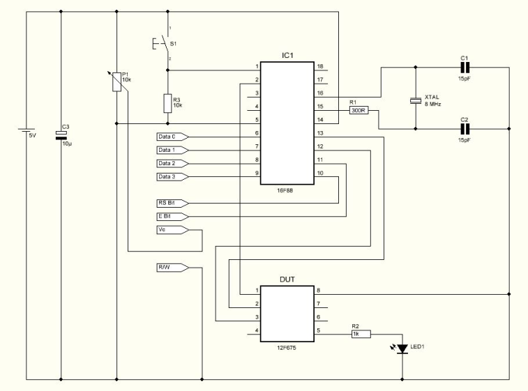
This project has the ability to calculate what is the appropriate osccal value for the 12F675 microcontroller.

Schematic

Schematic

Parts List

R1                   300 ohms resistor
R2                  1K ohms resistor
R3                  10K ohms resistor
P1                   10K Potentiometer
C1                   15pF capacitor
C2                  15pF capacitor
C3                  10uF capacitor
Led1               3mm green led
LCD               8X2 LCD
XTAL            8Mhz cristal
IC1                 16F88 microcontroller from Microchip
S1                   Push button

Others:

Box
8 PIN IC SOCKET
PCB
Hex program for the microcontroller

How it works

The program loaded in the 12F675 device which has no osccal value will force a pulse on GPIO.4 and it will make a loop while increasing the osccal value internally.
GPIO.5 will send the current osccal value used for each pulse sent. Because the device has no calibrated osccal value, the pulse will be variable. The circuit will wait until it receives the correct pulse. When the correct pulse is received, it will stop the test and display the osccal value used when the correct pulse was measured.
 
The value displayed is in Hexadecimal format which means it can be used without conversions directly to the device’s memory.

HEX Program

The Hex program named Oscfind1 must be saved in the 16F88 microcontroller’s memory before soldering on the PCB.
 
The Hex program named Oscfind2 must be saved in the device’s memory ( 12F675 ).

Testing

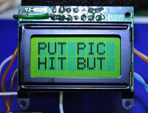
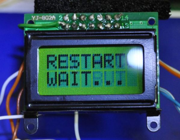
Turning on the circuit, it will display the name of the project and then it will display the message “ Put Pic – Hit But “. At this point it’s possible to place the 12F675 device on the socket and press the push button.


photo_2

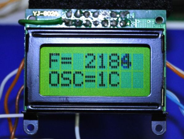
Pressing the push button S1 the circuit will start to measure the signal from the 12F675 device and will count the pulses. The display shows the pulse signal being measured and the current Osccal value.

photo_3

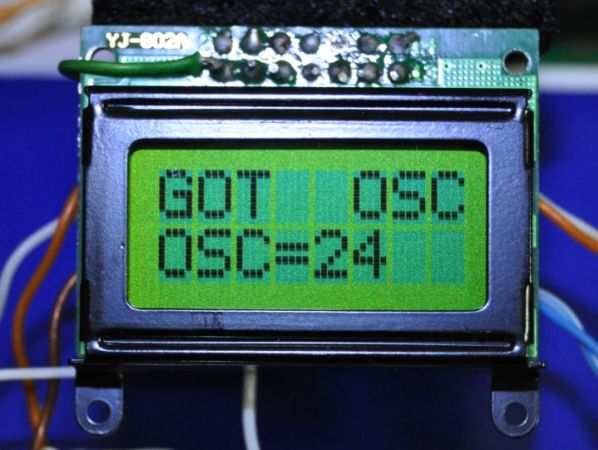
When the pulse sent by the 12F675 device matches the requested pulse length the circuit will stop the device and display the recommended osccal value.

photo_4

Since the circuit controls the power of the 12F675 device, at this point is possible to remove the device from the socket and place a new one. Pressing S1 the circuit will start a new test.

photo_5

Conclusion

This is a very interesting circuit for the microcontroller beginner. Not only for recovering lost osccal values but also to understand some microcontroller characteristics.
The crystal must be a good quality crystal or precise results may not be ensured.
The circuit uses an 8X2 LCD making it a portable project.

USB Low Pin Kit

SAMSUNG DIGIMAX A503

Introduction

USB is very common interface today. If you look around, many of devices today comes with a USB port. Computers, printers, routers, usb keys, etc. All this devices have a USB controller inside. These devices can be divided in two groups:

  • USB Host (like a computer, routers, modern LCD TV’s);
  • USB Device (like flash drive, mouse, keyboard);

Most of hobby electronic projects still are in RS232 serial communications world. Think in that great market,
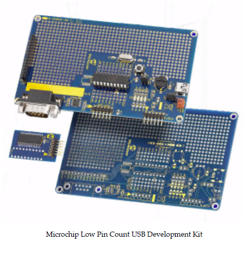
Microchip create a very smart line of microcontrollers, USB capable, to move your projects to future. They have great introductory kits, one of them is the “Low Pin Count USB Development Kit”.

microchip_low_pin_count

These boards contain a PIC18F14K50 microcontroller and can help you to grow up your USB knowledge and with a few steps you still able to create a mouse device, a USB temperature meter or a USB-Serial converter.

My Project

My idea is create a little board with most of Microchip kit, but less parts then all these boards. Only the basic
components to get the microcontroller up and running the Microchip USB Library examples. PIC18F14K50 is a really
basic device and after some research I found what you can do and what you can not do with it:

  • What you can do: USB HID (Human Interface Devices) like mouse, keyboards, sensors, serial-usb converters, etc
  • What you can not do: USB storage devices, like USB flash drives

USB storage is a problem because of memory limitations on PIC18F14K50 family.

Design

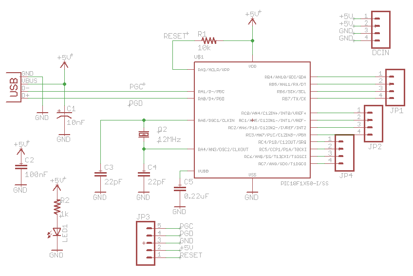
The circuit design is very simples. Basically all you need is

  • PIC18F14K50;
  • 12MHz Crystal;
  • USB connector;

The circuit still have a ICSP header for device programming and debugging. It’s USB powered, so you can pay
attention on current drain (500mA max.). See below:

Schematic

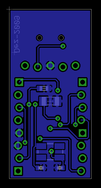
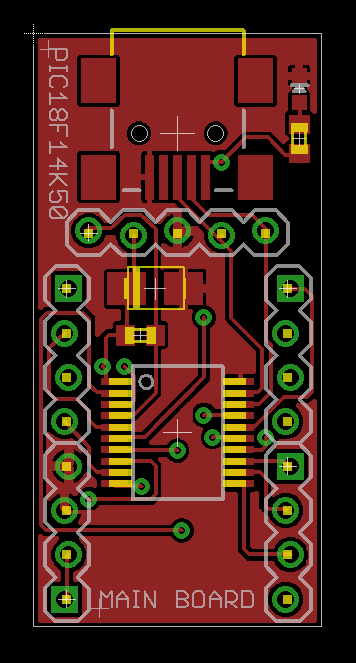
The board is very simple and clean. I want a little device to put on breadboard or stay alone, with headers to
connect wires and breakout boards. I don’t put a RESET switch on board because I think it’s not necessary (does your mouse have a reset button?). The final design you can view above:

board_bottom_layer

Bottom Layer

board_top_layer

Top Layer

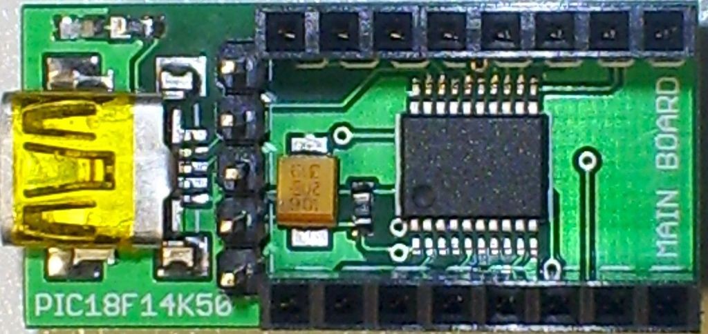
SAMSUNG DIGIMAX A503

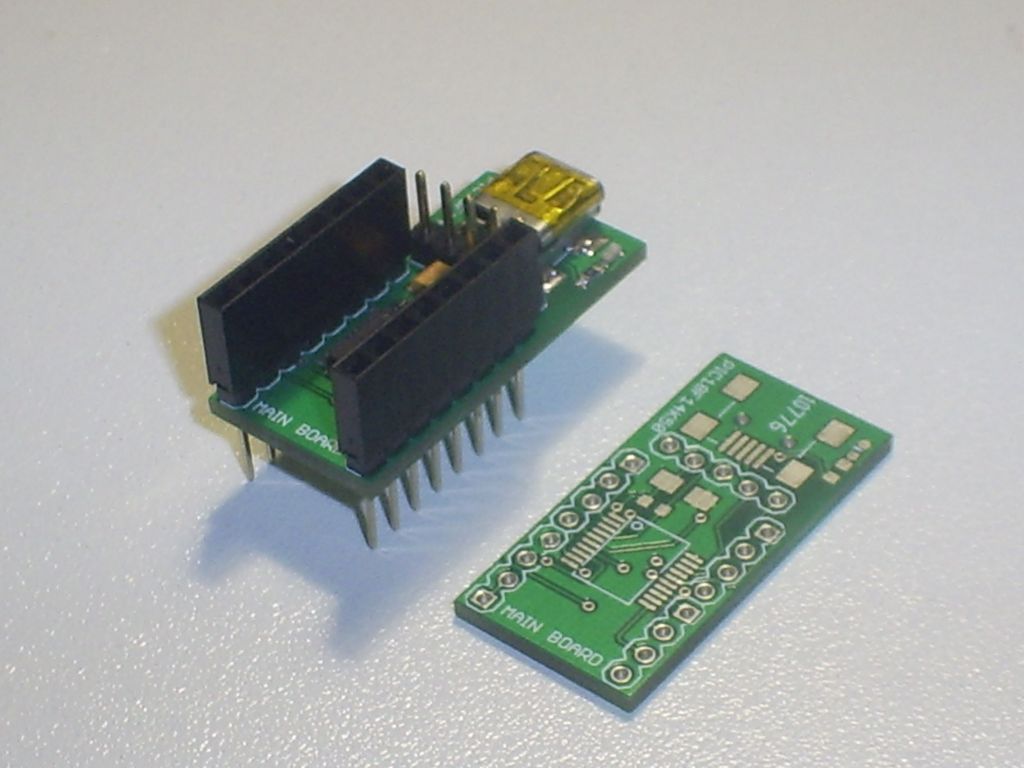
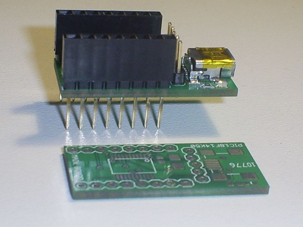
Real board after solder

Conclusion and Tests

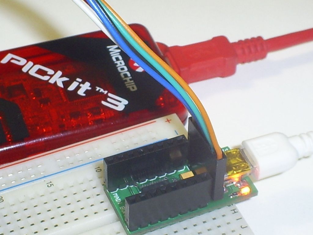
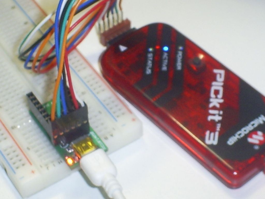
After finish the project I make some tests. The board is very functional and easy to use. To program it I use my PicKit3 program, directly in ICSP connector:

SAMSUNG DIGIMAX A503

Programming via PicKit3

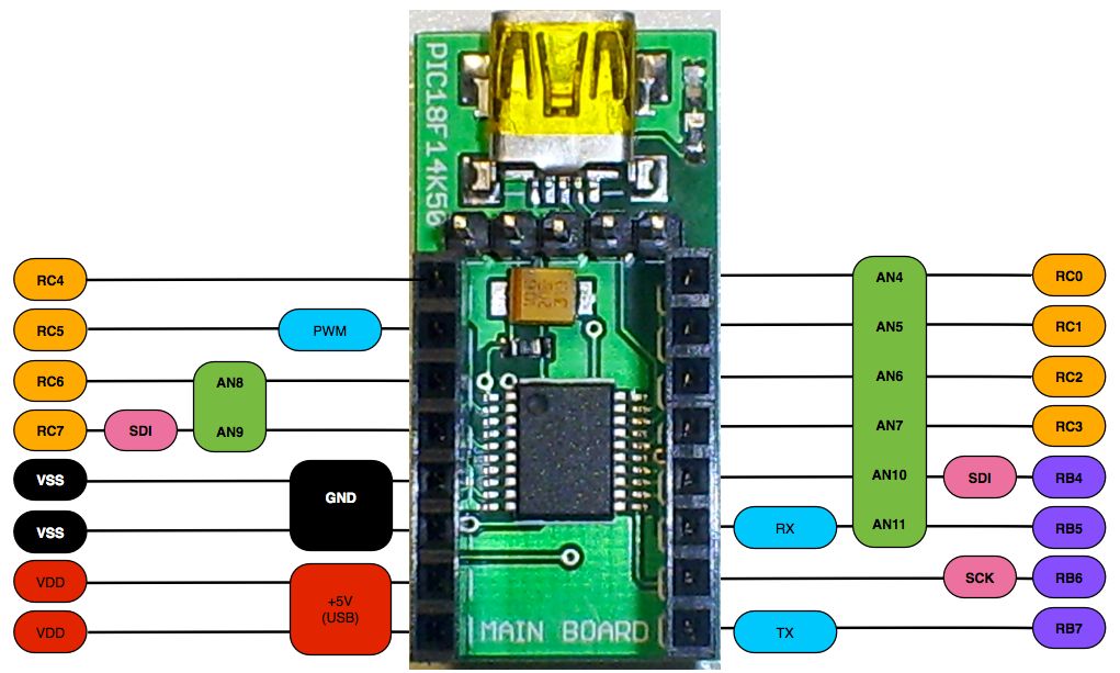
Because the board space, there’s no labels on MCU pins, so I draw a little card to help my mind:

USBLowPinKit_ReferenceCard

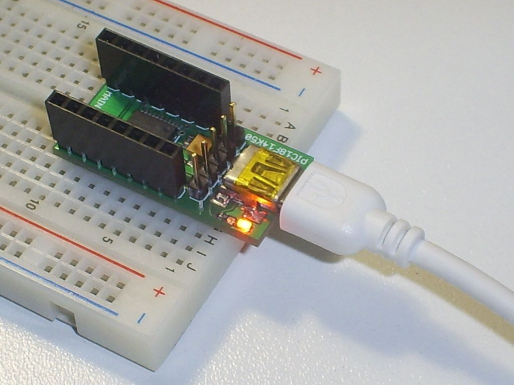
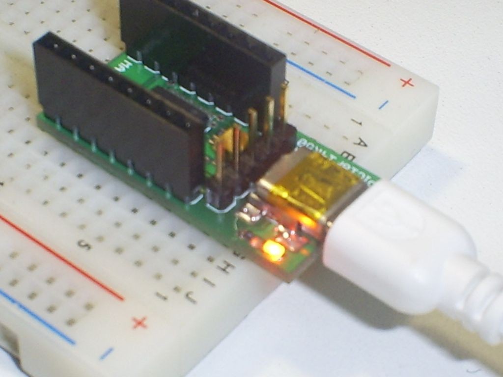
I’ve used long terminal header, to plug it in breadboard. See the next pictures:

SAMSUNG DIGIMAX A503

SAMSUNG DIGIMAX A503

After some tests I’m very happy, because:

  • All Microchip original kit projects work with my board;
  • My knowledge on USB grow up;
  • The board is very small, so designs like a mouse with accelerometers is easy to implement;
    Rodrigo

Photos

board

SAMSUNG DIGIMAX A503

SAMSUNG DIGIMAX A503

SAMSUNG DIGIMAX A503

SAMSUNG DIGIMAX A503

SAMSUNG DIGIMAX A503

SAMSUNG DIGIMAX A503

TOP PCB Companies