EPROM adapter for ATMEL 89 Series Flash Microcontroller

sch

Devices

The EEprom programmer software supports the following devices.

28C16 28C256 28C17 29C256 28C64

Hardware

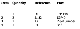
Diode D1 and resistor R1 provide the VDD isolation when programming the 24 pin devices. The jumper J3 must be shorted for 24 pin devices, and open circuit for 28 pin device programming. Following EEPROMs are pin compatible with their EPROMs version,

28C16 —> 2716

28C64 —> 2764

29C256 —> 27256

The software for this adapter is located here: http://chaokhun.kmitl.ac.th/~kswichit/E2RomPgm_web/PgmE2w.zip

Parts

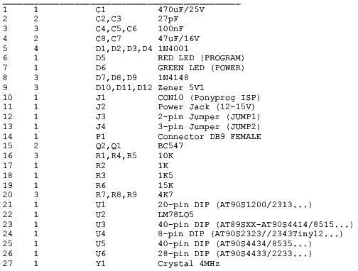
parts


ATMEL 89 Series Flash Microcontroller

Programmer Ver 2.0

The original and true author of this programmer is M Asim Khan. asimkhan@sat.net.pk

Original plans can be found at: http://chaokhun.kmitl.ac.th/~kswichit/Pgm89v2/Pgm89_2v0.html

The required software for this programmer is located at:

http://chaokhun.kmitl.ac.th/~kswichit/Pgm89v2/Pgm89w.zip

With an optional adapter at J1 and a different software it is possible to program some parallel EPROMs like the 28C16, 28C17, 28C64, 28C256, 29C256. The software for this adapter is located here: http://chaokhun.kmitl.ac.th/~kswichit/E2RomPgm_web/PgmE2w.zip

More info for the EPROM adapter in another document (PDF 198KB) that can be found in downloads.

Also check EPROM adapter for this programmer.

Parts

parts


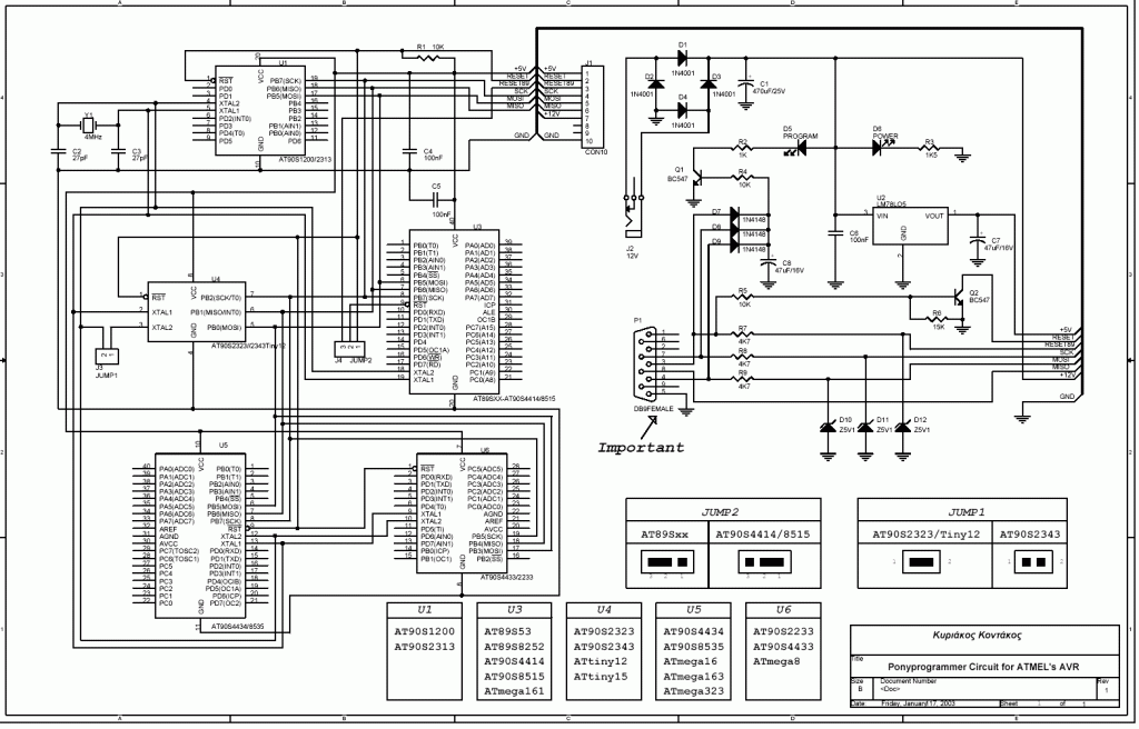
Ponyprog Circuit for ATMEL’S AVR

schematic

The ATMEL AVR programmer works with the Windows program “Ponyprog” which works under 95, 98, XP, … and can be found athttp://www.lancos.com/prog.html

On board the AVRs that can be programmed are those in the schematic. For other members of AVR family or the rest programmable ICs that Ponyprog can program, there is the J1 connector (CON10) which allows expanding the programmer’s hardware. See Ponyprog’s site for other’s ICs Ponyprog circuits. The JUMP1 jumper is there to connect the crystal’s circuitry to the 8-pin AVRs or to disconnect it. Some AVRs have internal RC oscillator and an external XTAL is not allowed or needed. Check the JUMP1’s table and the datasheet for the AVR of your choice for more details. The JUMP2 jumper is there to allow programming a member of the AT89Sxxxx family or the AVR’s AT90Sxxxx & ATmegaxxx family.

parts

PlayPIC

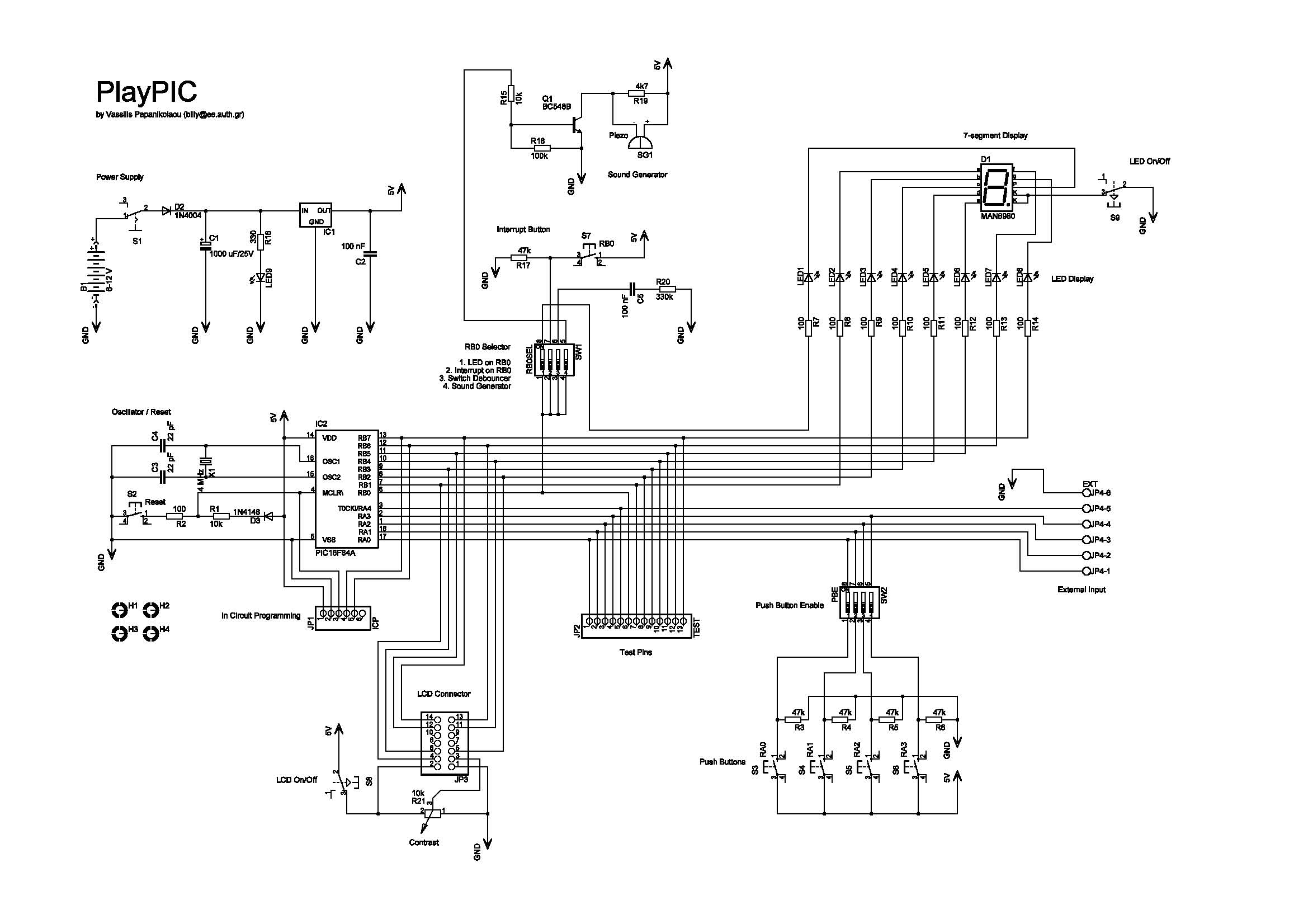
PlayPIC Schematic


A Tutorial Board for the PIC16F84A Microcontroller.

This is a new design of a tutorial board based on the popular PIC16F84A microcontroller. It features eight single leds, a 7-segment display, an LCD display and five push buttons. It is an ideal solution for the beginner to take his/her first programming steps in the world of microcontrollers. Having an in-circuit-programming (ICP) header, it can be easily reprogrammed without unplugging the microcontroller each time, provided that the programmer also supports this feature (like OziPic’er).

Connections

PIC16F84A Feature
RA0 JP2 – S3 – JP4
RA1 JP2 – S4 – JP4
RA2 JP2 – S5 – JP4
RA3 JP2 – S6 – JP4
RA4 JP2 – JP4

PIC16F84A Feature
RB0 JP2 – LED1 – 7 Seg (dp) – S7 Debounce – Buzzer
RB1 JP2 – LED2- 7 Seg (a) – LCD RS
RB2 JP2 – LED3- 7 Seg (b) – LCD R/W
RB3 JP2 – LED4- 7 Seg (c) – LCD E
RB4 JP2 – LED5- 7 Seg (d) – LCD DB4
RB5 JP2 – LED6- 7 Seg (e) – LCD DB5
RB6 JP2 – LED7- 7 Seg (f) – LCD DB6
RB7 JP2 – LED8- 7 Seg (g) – LCD DB7

Description

  • S1 switches the board on and off. When on, the indicator led LED9 is lit.
  • S2 resets the microcontroller.
  • S8 switches the LCD display on and off
  • S9 switches the eight individual leds AND the 7-segment display on and off.

Push buttons S3 to S6 correspond to RA0-RA3 inputs. They are enabled or disabled by the SW2 dip switch.

The SW1 dip switch enables or disables the following features :

  1. Connects RB0 (used as output) to LED1.
  2. Connects RB0 (used as interrupt input) to S7.
  3. Enables the debouncing circuit for interrupt switch S7.
  4. Connects RB0 (used as output) to the buzzer.

This dip switch must be either 1000 or 0100 or 0110 or 0001.

The 7-segment display is always connected to the individual leds. Its seven segments correspond to LED2 to LED8 (RB1 to RB7) and the decimal dot to LED1 (RB0). This correspondence enables the 7-segment display to work together with the interrupt switch S7, which is connected to RB0.

  • JP4 is an 6-screw external input connector for RA0-RA4. When used, the corresponding input switches S3-S6 must be turned off by SW2. Last screw is ground.
  • JP2 is a 14 pin test terminal. A voltmeter or logic analyzer can be connected any time to monitor the signal traffic in the circuit. Last pin is ground.
  • JP1 is the ICP header. When in-circuit-programming is performed, the board must be OFF (by S1), as well as the LCD (by S8) and leds (by S9).
  • JP3 is a 14-pin connector for the LCD module. Contrast can be adjusted by trimmer R21.

The board can be powered either by a 9V battery or a 6-12 V power supply.

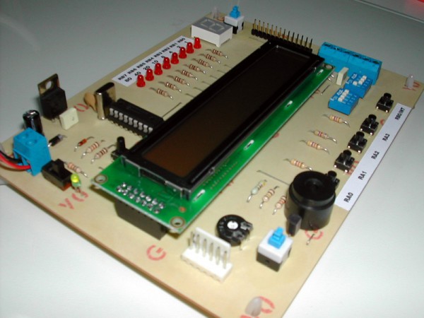
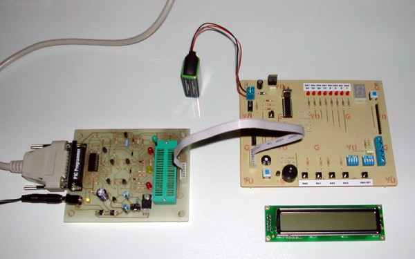
PDF versions of the schematic and PCB are included. The board has been sucessfully build and it is depicted on the following photos.

PlayPIC 1 Small

PlayPIC 2 Small

The right photo shows the in-circuit-programming procedure with the help of an appropriate programmer (like OziPic’er) which features an ICP header. In order for the procedure to work correctly, the LCD module has to be disconnected from its socket during programming.

Any futher ideas, comments and corrections are mostly welcome to billy@ee.auth.gr

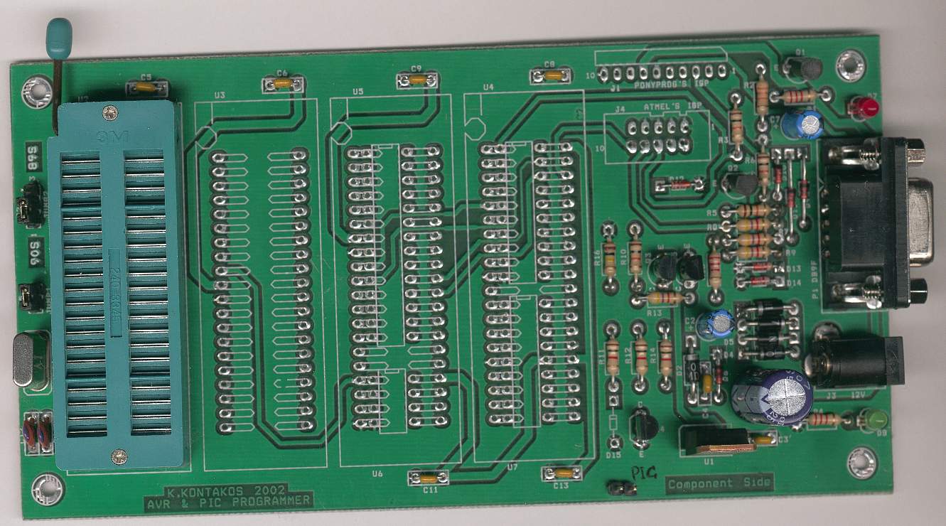
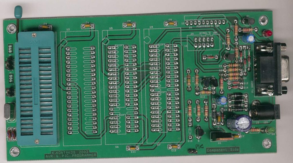
Ponyprog Circuit for AVR & PIC16F84

ponyprog_assembled

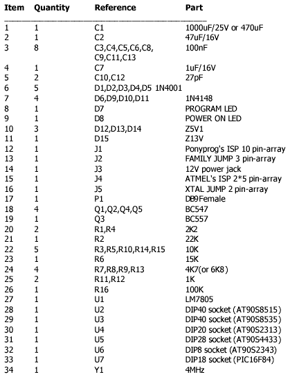
parts

Schematic

schematics


Comments

All resistors are 1/4W.The circuit is powered by 9…15V DC or AC. When In Circuit Programming (ISP) connectors are used, is possible the programmer to be powered from target’s power source. Diodes D2 and D6 protect the regulator LM7805, when target’s power is used.

‘ XTAL JUMP ‘ is used to cut XTAL when the AVR has internal RC oscillator enabled.

‘FAMILY JUMP’ is used to select which ATMEL’s family to program, AVR series (ATtinyXX, AT90SXXXX, ATmegaXXX) or 8051 series (AT89Sxxxx).

‘PIC JUMP’ is used to switch between Microchip’s PIC and ATMEL’s microcontrollers. With jumper ON only PIC can be programmed, while OFF can program ATMEL’s microcontrollers. If you don’t need to program PICs, you can leave their board area unsoldered. The PCB has been designed so that DIP sockets or ZIF sockets can be used. Because of its cost, it is recommended that only one ZIF is used combined with some pin-arrays to switch between the four different places.

The board must be connected to a PC COM port through a 9 pin to pin cable and work with the below application:

‘PonyProg2000 – Serial Device Programmer

Copyright (C) 1997-2001 by Claudio Lanconelli

E-mail: lancos@libero.it

Download last version of PonyProg2000 at the address:

http://www.LancOS.com ‘.

Supported microcontrollers are:

ATMEL’s AVR series

ATtiny12, ATtiny15, AT90S1200, AT90S1200A, AT90S2233, AT90S2313, AT90S2323, AT90S2343, AT90S4414, AT90S4433, AT90S4434, AT90S8515, AT90S8535, ATmega8, ATmega16, ATmega161, ATmega163, ATmega323, ATMEL’s 8051 series, AT89S53, AT89S8252

MICROCHIP’s PIC series

PIC16x83, PIC16x84, PIC16F84A

And some other programmable ICs (memories, microcontrollers) which Ponyprog support but need a board adapter to be programmed through ISP connectors. For more information see Claudio Lanconelli site .

PIC diode tester

check_diode

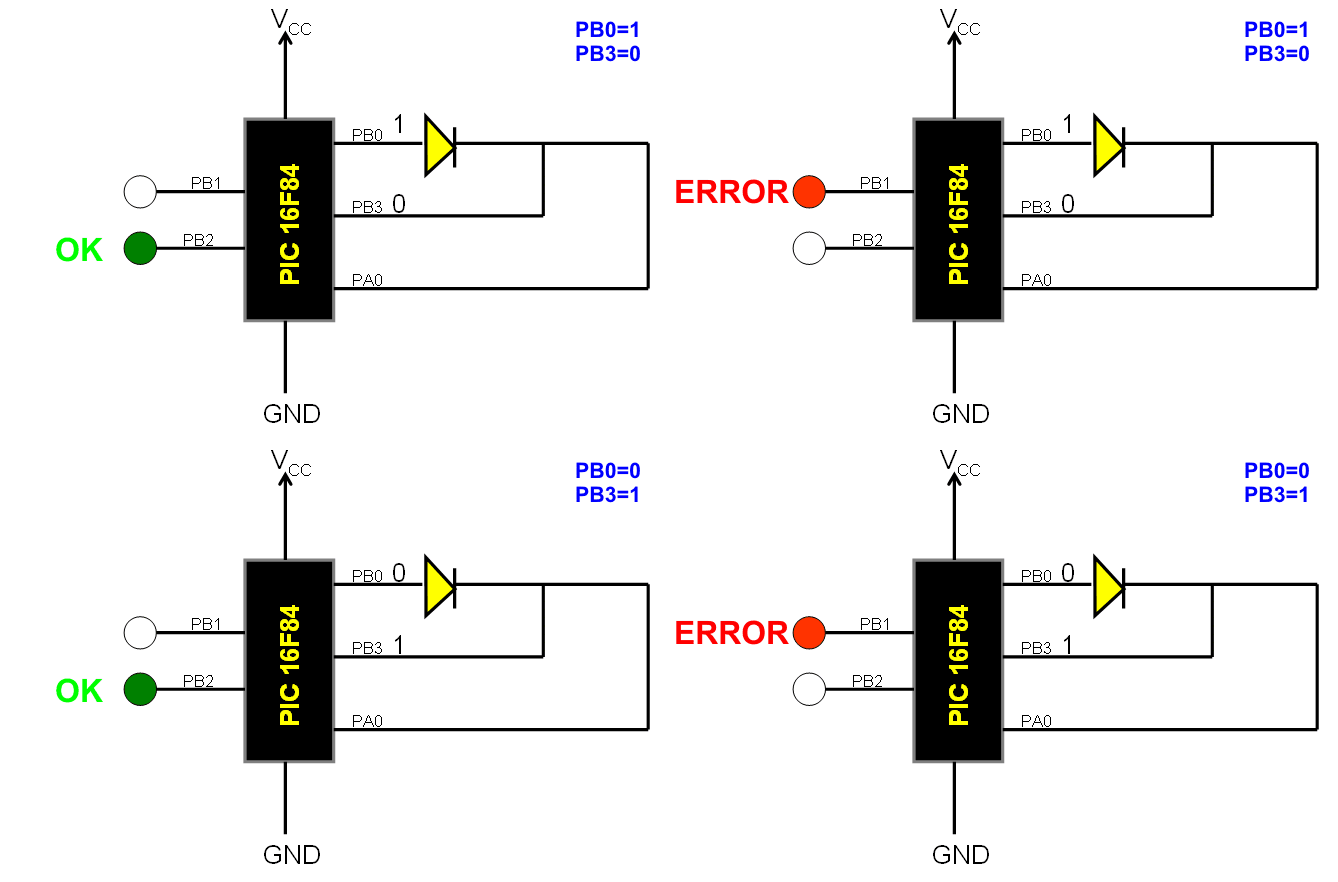
This is a simple use of the PIC 16F84 about a diode tester.

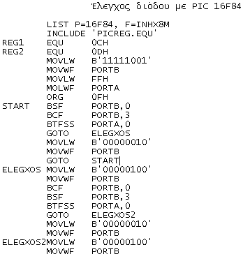
Test procedure : We set «1» to PB0 and «0» to PB3. If diode is ok and opens, then at PA0 we have «1». If PA0 is «0», then the the diode has problem. With the program we manage what the PIC will do in each situation . If PA0 is  «1», green led lights wich means that the diode is OK and if PA0 is «0» red led is lighting and the diode is problematic.

Test continuous as follows: We give «0» at PB0 and «1» to PB3. If diode is OK and opens, then at PA0 is «1». If PA0 is «0», then diode has problem. If PA0 is «1», green led lights that means that diode is OK and if PA0 is «0» the red diode is lights that means the the diode is problematic.

code

XBMC USB Controller

Photo-2

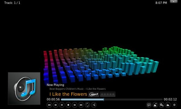
Fig.1 – XBMC Audio Player

For Media Center PCs

OpenHardwareLogoXBMC is a cross platform Media Center Application with 10-foot UI. In this project we develop USB port base controller for XBMC application. Main functionality of this controller unit is to provide remote control interface, LCD base player information panel and rotary encoder base controller for XBMC. With this given hardware design and software programs, user may be able to control XBMC without using standard input devices such as keyboard and mouse.

This device is design to work with XBMC Version 10.1 (codename Dharma) or newer versions. Older version of XBMC may not work this system because of the differences in its Web Control Interface. This system is design to work with XBMC – JSON RPC interface.
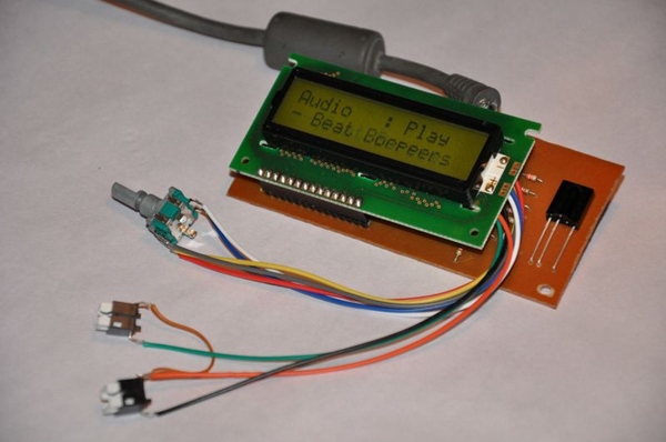
Photo-1_th

Fig.2- XBMC USB Controller

Microchip’s PIC18F4550 is a main hardware controller of this system. This microcontroller is used for USB interfacing, as LCD driver, IR base remote control data decoder and as a driver of the other input devices (such as rotary encoder and push switches). XBMC Controller’s USB interface is design to work as a USB HID class device.

This system is design to work with Microsoft Windows Operating Systems and we test this system in Windows XP Professional editions and some few Windows XP Embedded editions also. Supplied firmware of this system is design to work with Sony SIRC 20bit infrared protocol and supplied ini file is configured for Sony RMT-V408 remote controller.
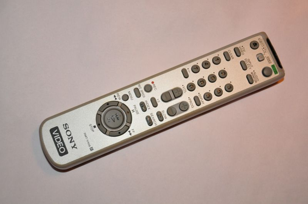
Photo-3_th

Fig.3- Sony RMT-V408 Remote Controller

Software Content

This system consists with two main software modules:

1. PIC18F4550 base software (firmware): This software module is developed using MikroC version 4.60.

2. Windows XBMC control application: Developed using Delphi 7 and work as a “virtual” Windows Service Application.

Before work with this system end user need to configure controller application for his/her remote control and for his/her software setup. This configuration file is located at \Controller\release folder with filename “mcci.ini“.

This ini file contains 3 main sections such as “xbmc“, “device” and “keymap“.

xbmc” section contain 3 parameters:

Address: IP address of the system where XBMC is installed. (In most of the configurations this parameter value set to defaults as 127.0.0.1)

Port: Port number assigned for XBMC web interface. (This value is need to verify with your XBMC network settings)

Location: full path and filename of the XBMC executable file.

device” section contain 2 parameters related with the USB controller. If your using default firmware, these values must be VID = 33824 and PID = 1.

If you alter firmware with different vendor ID and product IDs, make sure to change these values also.

keymap” section is used to assign functionalities to the remote control buttons. Key and the value formats for this section are described in below.
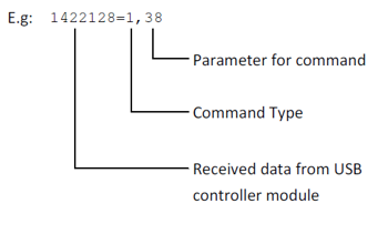
Diagramm-1

Command Type: Specify the type of the command as integer value. Valid command types are:

keymap” section is used to assign functionalities to the remote control buttons. Key and the value formats for this section are described in below.
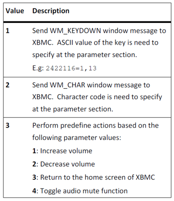
Diagramm-3

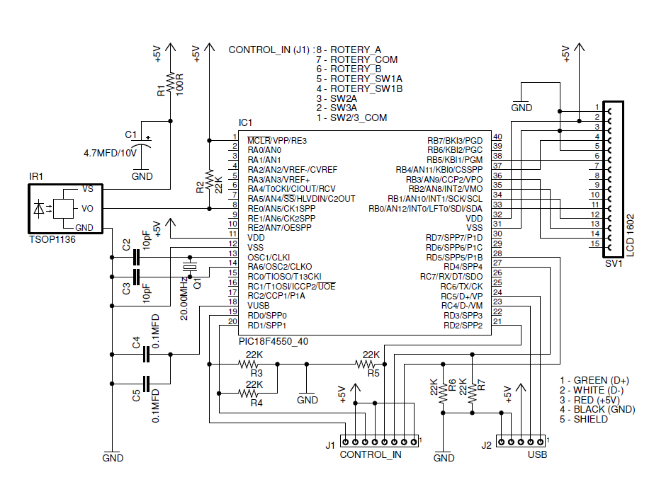
USB Controller – hardware connections

This given PCB design have 2 external connectors. J1 connector is used to connect rotary encoder and two push switches to the system. Connection diagrams of the J1 is illustrated in Fig. 4. J2 connector is used to connect USB cable to the system. Connections to the J2 is listed in below table:
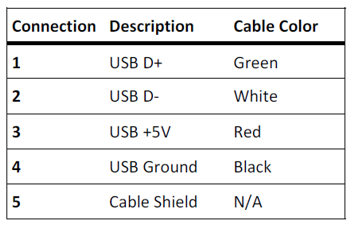
Diagramm-4

For J2 use standard 3feet 28/24AWG USB cable with USB male A connector.
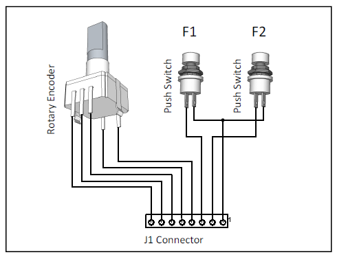
Diagramm-2

Fig.4- Connections to Connector J1

Installation and Initial Setup

Before start the initial setup we assume that target PC may have following minimum system requirements:

  • Windows XP or newer version of Windows operating system

  • XBMC 10.1 or newer version

  • USB 2.0 port

  • Suitable SIRC protocol base remote controller unit

 If the target system meets the above specified requirement, continue the system setup process as follows:

  1. Start XBMC and Click “System” and open “Network” tab.

  2. Under the “Services” change the following options: Allow control of XBMC via HTTP : ON Port : 80 Username : Password : (Clear both username and password fields)

  3. Press “Esc” key.

  4. Close XBMC.

  5. Extract supplied software package and make sure that mcci.ini file is properly configured.

  6. Connect XBMC USB controller to the PC. If device is working properly, Windows automatically detect the device and configure it to the target system.

  7. Start mcci.exe application. If everything is properly configured, XBMC starts automatically.

  8. Check the all XBMC functionalities with remote controller and controls on the XBMC USB controller.
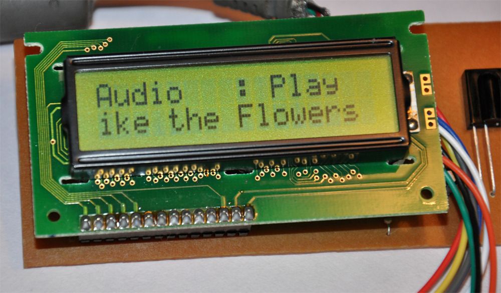
Photo-4

Fig.5- XBMC player information

Technical Specifications of the Device

Please note that all these technical specifications are valid only with the bundled firmware file (Version 1.0.0.31).

  • USB Version : 2.0
  • Device Class : 0x0
  • Vendor ID : 0x8420
  • Product ID : 0x1
  • Manufacturer : Dilshan R Jayakody
  • Product : Media Center Control Interface
  • Product Version : 0.1
  • Power Mode : Self powered 100mA Max
  • USB interfaces : 0x3 – HID class

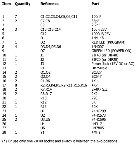
Components List
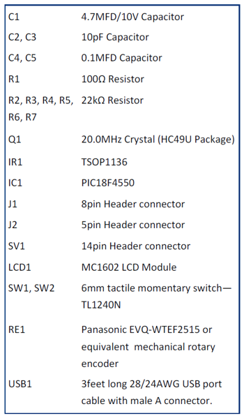
Diagramm-5

References

Schematic
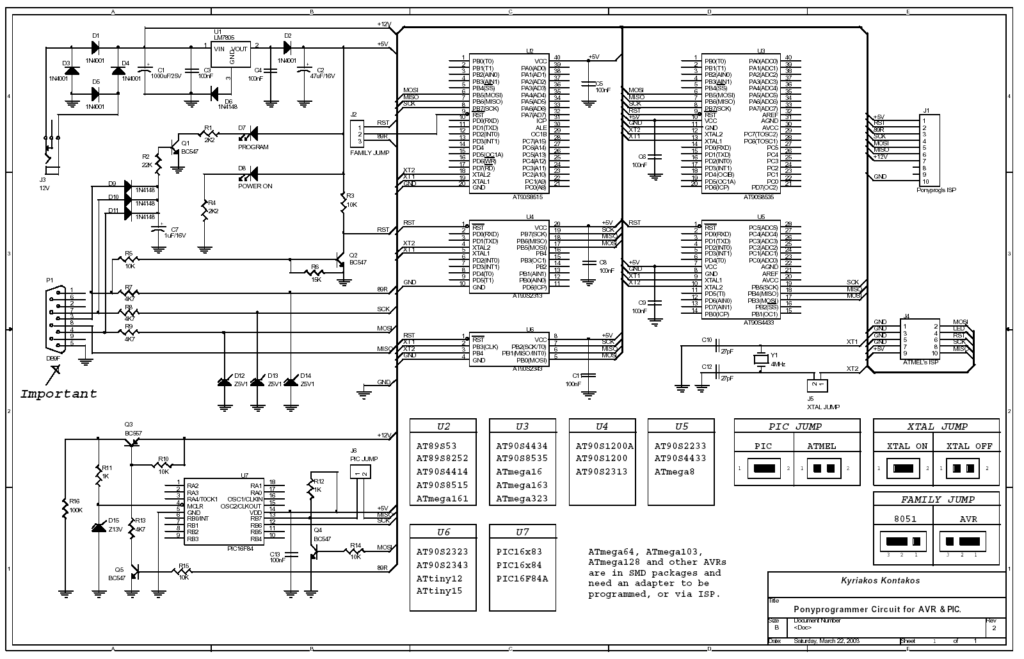
Diagramm-6

Open_Hardware (1)


USB Sound Card with PCM2702

PCM2702

Make a sound card is no more a complex issue. If you use great IC PCM2702 from BURR BROWN / Texas Instruments you can create a fully functional USB sound card. This sound card can be powered from USB port and has one stereo output. You don’t need to install any driver for Windows XP and Vista, because they are already inside. This is really plug and play.

Few months ago I have seen USB sound card called Alien DAC. The construction on the project web page inspired me to build this thing also.

Description

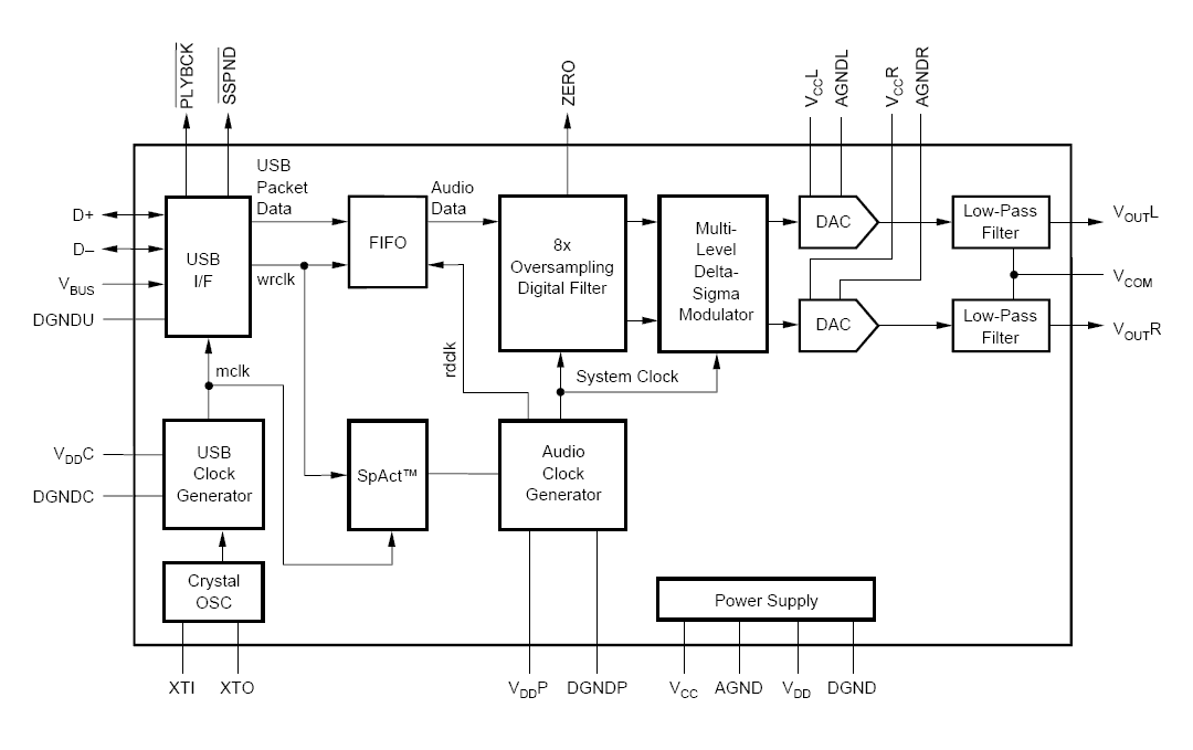
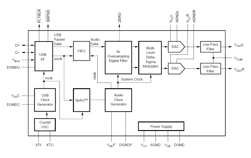
The core of this construction is 16-Bit Stereo Digital-To-Analog Convertor with USB interface PCM2702.

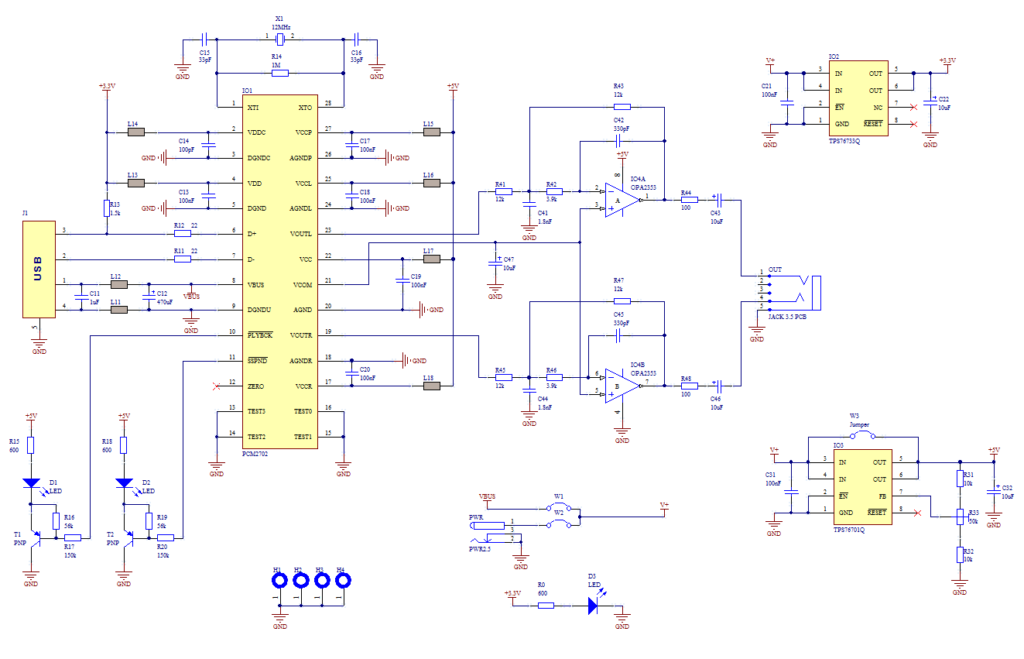
PCM2702 needs only few additional parts to work. The schematic is not complex. Sound card can be powered directly from USB port (jumper W1) or from external power supply (jumper W3). PCM2702 needs two power supply 3.3V (3V-3.6V) and 5V (4.5V-5.5V). I used fixed output voltage LDO TPS76733Q for 3.3V (IO2) and adjustable output voltage LDO TPS76701Q for 5V (IO3). Both LDO are produced by TI, I used this because I had it in my drawer. Any similar LDO can be used. Output voltage of IO3 should be set to little bit lower than input voltage to allow LDO good stabilization, in my case output voltage is set to 4.8V. Output voltage can be set by adjustable resistor R33. In case of low power supply, IO3 can be shorted by jumper W3. LED D3 signalizes power on.

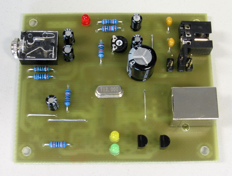
PCM_FRONT

Small ferrite beads are placed before all power pins of PCM2702 and in Vbus and GND of USB. These small beads reduce high frequency hum. I had a problem find this small SMD ferrite beads in local stores but finally I acquire few of them from old hard drive. They are not absolutely necessary, you can use zero ohm resistors instead of them.

Low-pass filter is placed in output signal path to reduce sampling frequency. An OPA2353UA dual op amp is configured as a stereo 2nd-order low-pass filter. Led diode D1 is illuminated when PCM2702 plays audio data received from the USB bus. Led diode D2 is illuminated when USB bus suspends audio data transmission to the PCM2702.

Schematic

PCM_SCHEMATIC


Photos

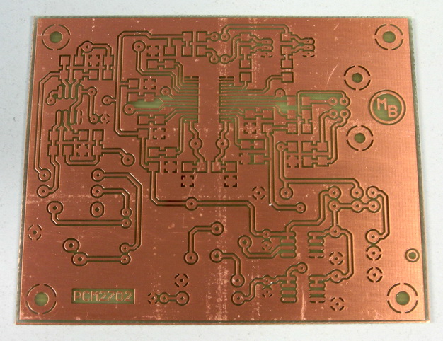
PCM_PCB

Bottom side of PCB (single side PCB, made by standard etching method)

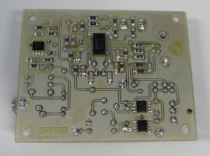
PCM_BACK

Assembled bottom side

Conclusion

This circuit works very well. I only shorted crystal during soldering so the circuit didn’t work, but after removing the short the sound card started to work. I have tested in Windows 2000, XP and Vista. It works in all mentioned systems. Drivers are present in operation system so the sound card is ready in few seconds after you connect it.

During writing this article I have found that PCM2702 is now not recommended for new design, but TI offer even better solution. PCM2704, PCM2705 have same functionality as PCM2702, but they include output filter. They are able to drive directly headphones. Volume and Mute can be controlled through SPI bus in PCM2705 or with pushbuttons in case of PCM2704. PCM2704 and PCM2705 are in TSSOP28 package. PCM2706 is similar to PCM2704 and PCM2707 to PCM2705 but in addition they have I2S bus. PCM2706 and PCM2707 are in TQFP32 package. I recommend using these new chips for new design (look at the TI web page).

Links

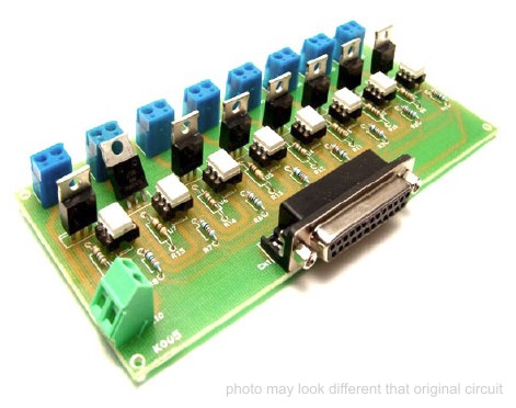
8 Channel LPT relay board

photo

Specifications

Channel Relay Board is a simple and convenient way to interface 8 relays for switching application in your project.

  • Input – 12 VDC @ 336 mA

  • Output – eight SPDT relay

  • Relay specification – 5 A @ 230 VAC

  • Trigger level – 2 ~ 5 VDC

  • Berg pins for connecting power and trigger voltage

  • LED on each channel indicates relay status

  • Power Battery Terminal (PBT) for easy relay output and aux power connection

  • Four mounting holes of 3.2 mm each

  • PCB dimensions 169 mm x 72 mm

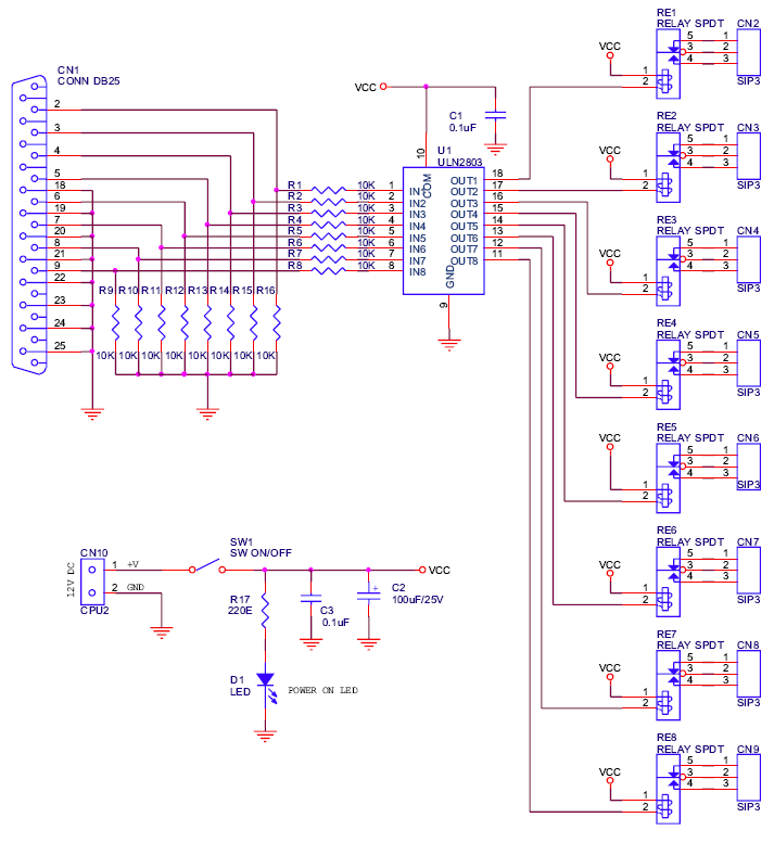
Schematic

schematic

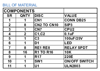
Parts List

parts


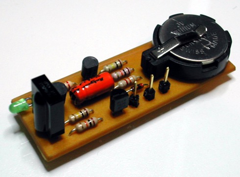
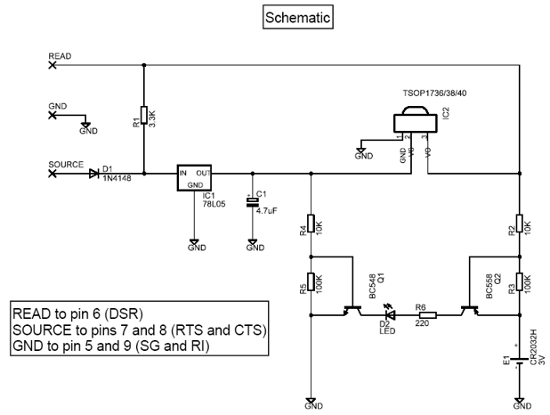
An Improved Infrared Receiver with Status LED

Billy's_Plug


This is the latest version of the Improved Infrared Receiver with Status LED which can control any desktop PC with an ordinary remote control. The project comes along with a small PCB in order to save space. It connects to the serial port as stated in the schematic and uses the freeware Girder (www.girder.nl) software together with Igor’s Plugin (www.cesko.host.sk/girderplugin.htm) to send commands to the PC. The potential uses of this device are countless (control MP3 players, CD and DVD players, radio and TV cards, even move the mouse cursor and shutdown the computer remotely !). Again, note that any ordinary remote control can be used by training Girder to learn its signals !

Schematic

schematic

Parts

R1 3.3K 1/4W

R2 10K 1/4W
R3 100K 1/4W
R4 10K 1/4W
R5 100K 1/4W
R6 220 1/4W
D1 1N4148
D2 LED 3mm
C1 4.7uF/16V Electrolytic
Q1 BC548
Q2 BC558

IC1 78L05
IC2 TSOP 1736/38/40 (may work with Siemens SFH506xx receivers also)

E1 CR2032 3V battery + PCB base
Misc Three pins to connect the serial cable (optional)

The improvements of this project compared to the ones already published in the internet is that it uses regulated power for the infrared receiver module (TSOP 17xx), has improved sensitivity (worked at a distance of about 10 m), and features a status led which is powered by an external battery source and is driven by two transistors. Upon signal reception, the led blinks to provide a visual feedback to the sender.

The PCB features narrow tracks (16 mil) so special care should be paid during the construction. The 4.7 uF capacitor is bent towards the board in order to save height if the circuit is to be placed in a small plastic box.

The Girder software for this project was preferred because it is first of all freeware, it is stable and customizable, features a large number of commands and supports user plugins. It is a bit difficult to learn at first, but after a while it deploys a great number of possibilities that other programs (even commercial ones) lack. Nevertheless, with the right corrections (pin changes) this project may be used with other software (WinLIRC, IRAssistant, Miriam, PCRemote) but no such testing has been carried out yet. This is maybe a good point for further search.

Add-on by nefelodamon@hotmail.com

The receiver also works with WinLirc 0.6.5 ( http://winlirc.sourceforge.net/ ) according to the
following pin connections and declared as a DCD device :

ΙR Reciever Pin Numer
Source 7 (RTS)
Ground 5 (GND)
Read 1 (DCD)

TOP PCB Companies