Infrared Receiver with status led

IR1

schem


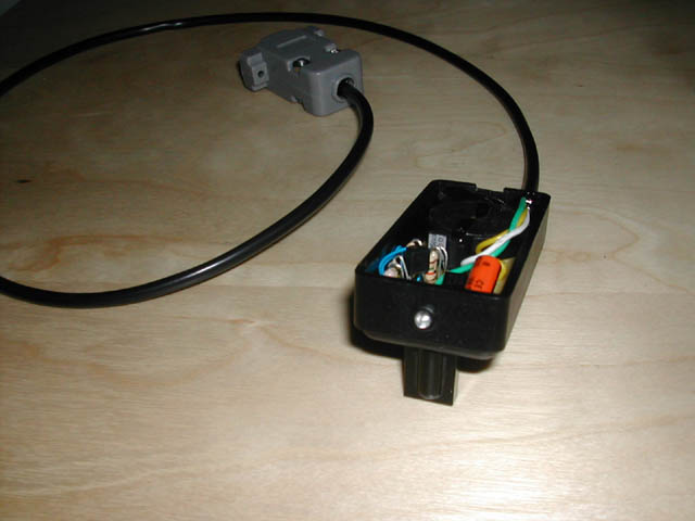
This is a general purpose serial port infrared receiver. With the help of appropriate software (see below) you can control different functions of your pc from a distance. For example you can control your home cinema settings (volume, play, pause, stop etc), your winamp etc.

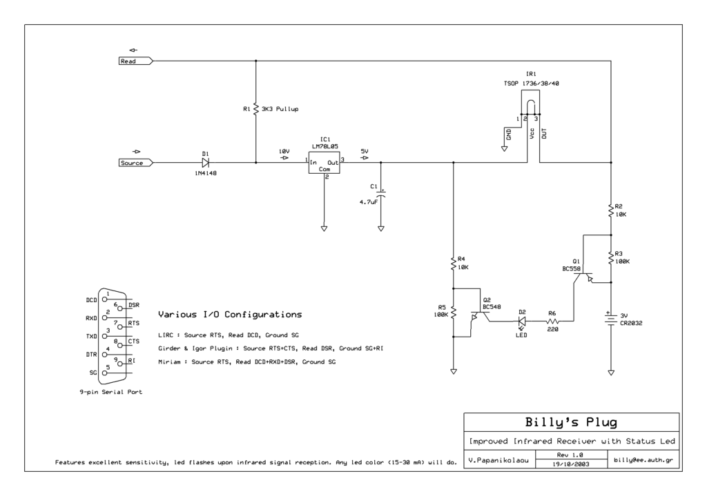
It<align=”center”> uses for receiver TSOP 1738 (38 KHz) but it worked well with TSOP 1736 (36 KHz) and a remote Sony which works at 40Mhz.

The two transistors light up the led when a signal is received. Any kind of led will fit.

The software that can be used are:

Girder + Igor Plugin
WinLIRC
Miriam
IRAssistant

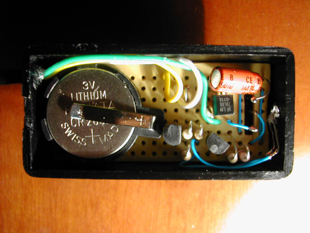
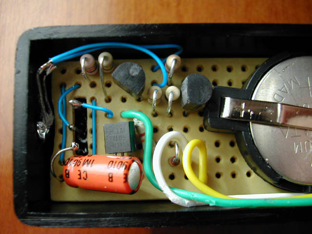
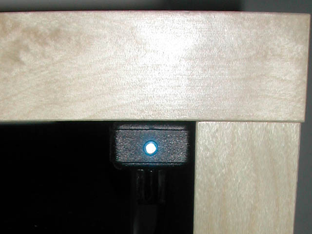
Below are some pictures from the finished device:

IR2

IR3

IR4

LCD2LPT with LIRC

The “LCD2LPT with Lirc circuit is the compilation of two circuits found on the net on a single board. The first is LCD to LPT interface and the second an IR remote control interface using http://www.lirc.org program.

Schematic

schematic_1


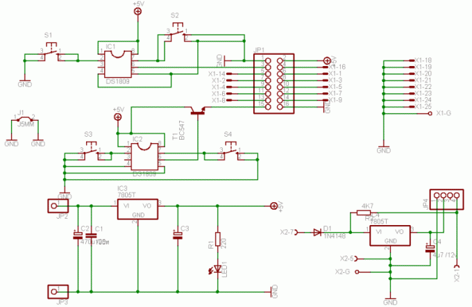
The main circuit for LCD connection to LPT was modified adding a backlight and contrast control using 4 push buttons. Responsible for the adjustment are the two DS1809 ICs made from Dallas-Maxim semiconductors along with 2 buttons for each adjustment.

IC1 with the use of S1(+, Up) and S2(-, Down) controls the Contrast of LCD and IC2 with the use of S3(+, Up) andS4(- , Down) and the help of transistor  T1, controls the backlight intensity.

schematic_2

IC3 is a 7805 regulator that stabilize the power line of the circuit. There is also a filtering capacitor that helps the transient discharge of the circuit preventing any damages to the ICs.

To JP2 you must apply 12V and if you wish you can add a polarity protection diode (1N4007).

For the IR receiver you must read the site http://www.lirc.org. The only thing i have to add up is to remove pin3 during contraction and read the receiver’s IC datasheet to help you out connecting it right.

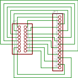
An adaptor for the LCD is also included so you can use a ribbon cable for the connection with the main circuit.

MSF Radio Time Clock

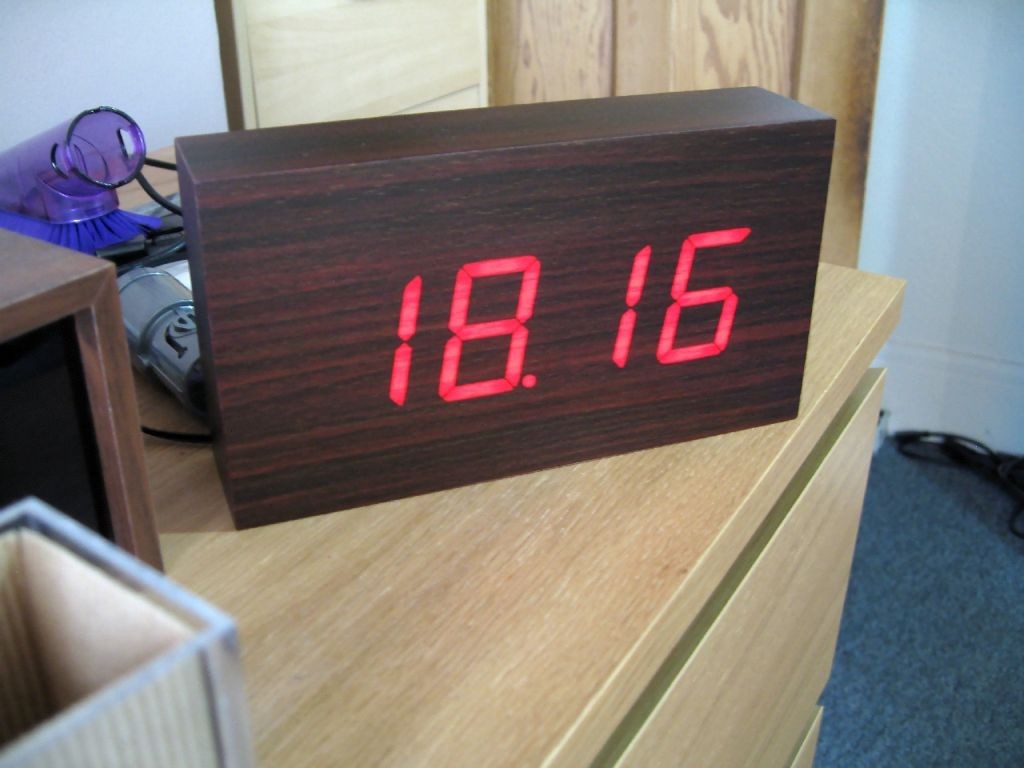
msf_clock_01

Introduction

The National Physics Laboratory broadcasts a time signal, previously known as the Rugby clock but now called “Time from NPL.” Its most commonly known as the MSF signal due to it originally being identified in Morse code those letters. It is broadcast from Anthorn on 60kHz. Many commercial clocks use it to automatically set themselves.

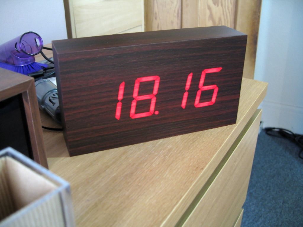
I decided to convert a digital clock I bought into one set by the MSF signal. To make the project more interesting I decided to use the ATtiny2313 microcontroller with only 2k flash ROM and 128 bytes of RAM.

Features:

  • Automatically set by MSF time signal
  • Bright, flicker free display
  • Alarm with choice of 5 polyphonic melodies
  • Hour chime with choice of melodies and no chime between 00:00 and 08:00

Hardware

The original clock electronics used two PCBs, one for the 7 segment LEDs and another for the clock controller and support hardware. I started by tracing the connections between them and mapping out how the display worked.

The display is multiplexed with simple transistor switches for the common anode. Only the middle two 7 segment displays have dots. I connected the anode transistors to the AVR with 2k2 resistors to limit current and the cathodes to a 74HC595 shift register via a ULN2803 Darlington array. I removed the controller IC and all other unused parts.

The AVR uses a 12MHz crystal which is accurate enough for keeping time. In my initial tests on the bench it varied by less than one second per day, but when installed in the clock case it looses about 3-4 seconds over 24 hours. Since the time is re-synchronised with the MSF signal every night that is more than adequate.

An MSF receiver module is connected to the AVR. I bought it for a few pounds and it works very well, although like most low frequency time code receivers it is extremely sensitive to noise. The multiplexed display has to be turned off while it is in use, so it is not possible to see the current time when it is being re-synchronised. I had to use a long USB cable for programming during development because the electrical noise from my PC was interfering.
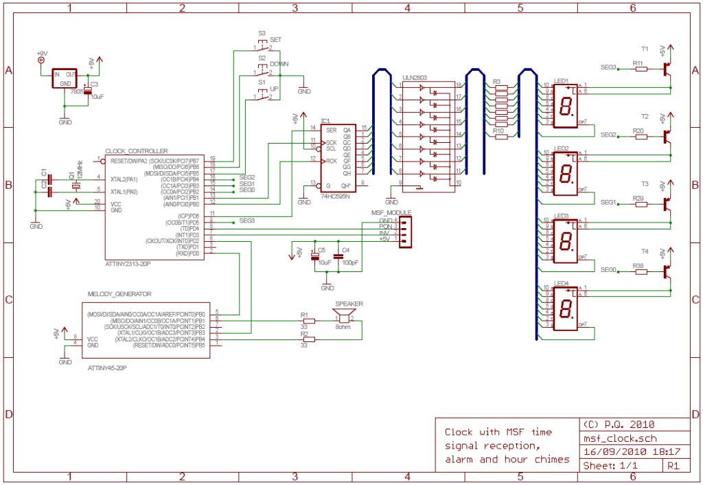
Schematic

Firmware

ATtiny2313 memory use summary [bytes]:
Segment   Begin    End      Code   Data   Used    Size   Use%
-------------------------------------------------------------
[.cseg] 0x000000 0x0007f8   2006     34   2040    2048  99.6%
[.dseg] 0x000060 0x000060      0      0      0     128   0.0%
[.eseg] 0x000000 0x000000      0      0      0     128   0.0%

 Time keeping is via an interrupt that also handles display multiplexing. The display is multiplexed at 100Hz which translates to a 400Hz timer interrupt (4 digits x 100Hz). The interrupt also sends signals back to the main code when minutes and hours increment.
msf01

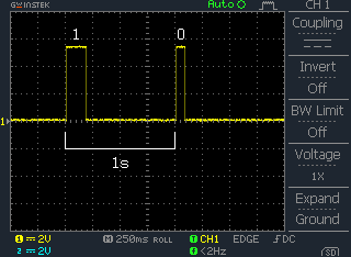
Oscilloscope trace of MSF signal

The MSF protocol represents binary bits with differing length pulses which are generated by switching the carrier signal on and off. The main two are 100ms (zero) and 200ms (one). The start of a minute is signaled with a 500ms pulse and towards the end of the minute cycle the parity bits can be 300ms long.

 MSF bit  Meaning Format
 00  Start of Minute Marker  500ms pulse
 01..16  DUT1 offset
 17..24  Year  8 bit BCD 00..99
 25..29  Month  5 bit BCD 01..12
 30..35  Day of Month  6 bit BCD 01..31
 36..38  Day of Week  3 bit BCD 1..7
 39..44  Hour  6 bit BCD 00..23
 45..51  Minute  7 bit BCD 00..59
 52  End of Minute Marker  Always 0
 53  BST change warning  1 bit flag
 54  Year Parity  Odd parity bits 17..24
 55  Month Parity  Odd parity bits 25..35
 56  Day of Week Parity  Odd parity bits 36..38
 57  Time Parity  Odd parity bits 39..51
 58  BST flag  1 bit flag
 59  Unused  Always 0

For details of the data format the Wikipedia page has some information about the signal which is mostly correct. The NPL documentation is also quite useful.

MSF reception requires fault tolerant code. Even under ideal conditions the signal is likely to contain noise. The decoded signal also has to be validated before being accepted.

The MSF reception routine waits for a pulse to start and then measures the length using a 100Hz timer. It rejects pulses (or drop-outs) of less than 5ms as noise. There is ±20ms leeway when decoding pulse lengths.

Once one complete minute’s worth of pluses have been received they are decoded, sanity checked and parity checked. If the signal looks valid then the decoded data is stored and a second signal is received. If that second signal also passes all checks and gives a time exactly one minute after the first then it is deemed correct and the clock synchronised.

Synchronisation takes place when the clock is first powered on and again at 3AM every night. 3AM was chosen to avoid inconveniencing the user and because there is less RF interference at night.

A note about MSF signal accuracy. The broadcast time is supposed to be within 1ms of UTC. However, there is propogation delay between the transmitter and the receiver which cannot easily be measured or removed automatically. Based on where I live I estimate the delay to be around 275ms. GPS time compensates for this delay.

User Interface

The clock is controlled by three buttons on the back. Since the clock uses the MSF signal to set itself automatically there is no way to set it manually. In any case there is not enough free flash memory to implement a time setting interface.

Holding down the SET button for one second enters setting mode. The UP/DOWN buttons change the setting and SET advances to the next one. The sequence is:

1. Alarm on/off

2. Alarm hour

3. Alarm minute

4. Alarm melody

5. Hour chime on/off

6. Hour chime melody

Buttons are debounced and repeat when held.

Melody Generator

I had planned to make the ATtiny2313 generate alarm melodies and hour chimes, but there was not enough code space left. I decided to modify ChaN’s Wavetable Melody Generator and control it with the 2313. ChaN is a bit of a genius when it comes to implementing things like this in an efficient yet flexible way with a minimum of external hardware required. In fact his WGM only requires an ATtiny45, speaker and power supply to work.

The requirements for the Melody Generator were multiple melodies and chimes. I decided to use music and sounds from Japan Rail (JR) stations. Probably only a 鉄道ファン, can understand why 🙂

wave

I started by creating a new wavetable (actually there is only one instrument so it isn’t really a “table”…) using a sample from the default TiMidity++ set. It had to be cut into two sections, the attack and sustain phases. Typically instruments that are percussive (e.g. pianos, bells, chimes) create a sudden transient sound when hit where the waveforms are non-symmetrical called the attack. They then quickly start to oscillate and fade out as energy is lost, called the sustain. Because the oscillating part of the sound is simply the same waveform repeated with ever decreasing magnitude it is only necessary to store one cycle and reduce its amplitude to zero over the length of the sustain period. This method also makes it easy to vary the length of the sustain.

I found MIDI versions of the melodies and chines I wanted and converted them to text with MIDINOTE. The text was then imported into Excel, re-exported to text in a more suitable format and cleaned up in Notepad++. Finally ChaN’s Perl script was used to convert them to AVR assembler include files.

ChaN’s code was altered to support multiple scores, each with it’s own sustain decay rate. I also added some code to interface the ATtiny45 with the main ATtiny2313 using a very simple protocol. The 2313 pulls an enable line low and then pulses a data line a number of times corresponding to the score it wants to have played.

The hardware is trivial – merely an 8Ω speaker connected directly to the AVR.

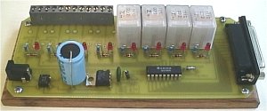
The 8Way Relay Board

8way


This board is designed specifically to control the 5-motor Robot Arm sold by Baycom Technologies. It has no input facilities, but it is less expensive than combining the I/O Board with the Relay sub-Board. If you need lots of relays and no input, this is the way to go.

Parts List

1 x PCB
8 x SPDT 12 volt Relays
1 x PCB mounted DB 25 Socket
1 x ULN2803 Integrated Circuit
1 x 1N4004 Diode
8 x 1N914 Diode
8 x 3mm Red LED
8 x 560 ohm 1/4 watt resistor
1 x 47uF Electrolytic Capacitor (up to 1000uF can be used depending on the power supply)
1 x 0.01uF (approx) Green Cap
1 x LM7812 Voltage regulator (T220 case)
1 x 1 amp Bridge Rectifier
1 x 2.1mm Power Socket
25 pin Serial Cable – Male to Male
12 – 24 volt power supply with 2.1mm Plug

Optional: 8 x 3way PCB mounted terminal mounts.

Assembly

Begin with the smaller items such as the 1N914 doides and then the IC. You can then start on the ‘taller’ items like LEDs, resistors, regulator, bridge, green cap, etc. Once you have the basic components soldered in, carefully install the DB25 socket. Make sure that none of the pins get bent over as you’re trying to wiggle everything into place. It’s a nightmare to unsolder the socket if you make a mistake! Leave the relays until last.

Any 12 -15 volt 1 amp minimum AC or DC power supply can be used.

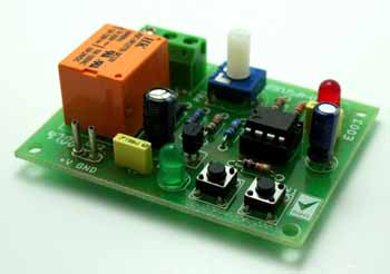
1 to 100 Seconds Timer

1_Sec_to_100_Seconds_Timer_PIC


This project is a 1 to 100 Seconds Timer based on 555 IC

Description

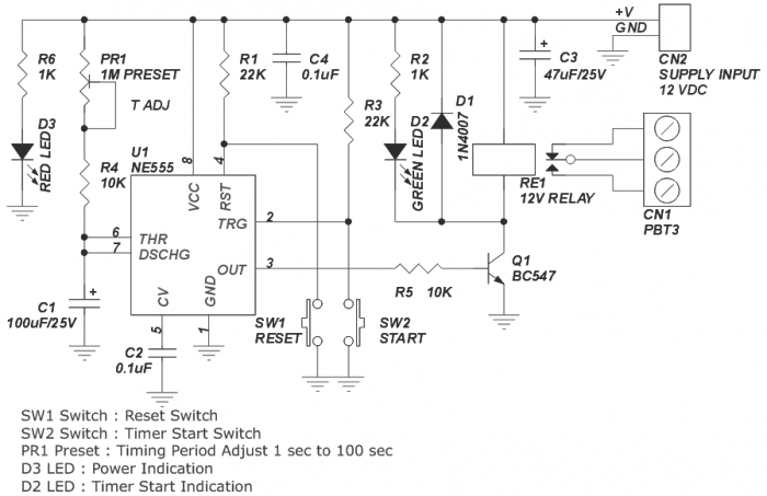
This project is a timer project and build around popular 555 Timer IC, It can be used for all application required a delay of up to 100 Seconds. Onboard board preset to adjust the required timer duration in range of   of 1 to 100 Seconds, Tact switch SW1 to reset the timer and SW2 to start the timer. LED D3 works as power indicator and LED D2 to indicate timer operation.

Load can be connected to CN1 Screw Terminal, Out-put has both the operation normally Open and normally closed. Circuits works on 12V DC and consume approx. 100mA current. Very useful project can be used in various applications like water irrigation system, Kitchen timer etc.

Specifications

  • Supply input 12 VDC @ 100 mA
  • Onboard start and reset tactile switch
  • Relay output: SPDT relay
  • Relay specification: 5 A @ 250 VAC
  • Relay state LED indicator
  • Preset adjustable range function
  • Power-On LED indicator
  • Screw terminal connector for easy relay output connection
  • Four mounting holes of 3.2 mm each
  • PCB dimensions 48 mm x 63 mm

Schematic

1_Sec_to_100_Seconds_Timer


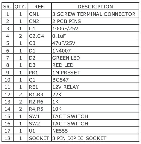
Parts

1_Sec_to_100_Seconds_Timer_bom

Long Duration Timer

002_PIC


This project is a long duration timer based on 555 timer IC.

Description

This timer project can be used to switch ON/OFF any device after a set time, this circuit can be used in lots of application like switched ON/OFF Radio, TV, Fan, Pump, kitchen timer, the circuit describe here its unique in its own.

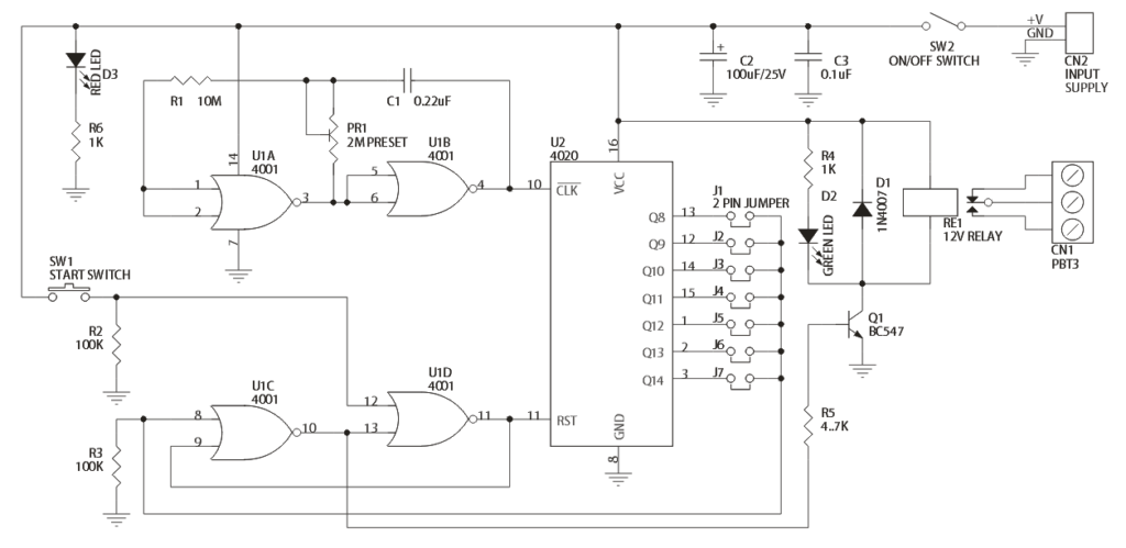
Project has been designed around two CMOS IC CD4001 and CD4020.  Two gates of CD4001 make the oscillator and rest has been configured as flip-flop, BC547 transistor is to drive the Relay. Circuit is pretty simple, has jumpers to set the required time duration, Preset is to set the 1Hz oscillator. SW1 is to start the timer, SW2 Power on/off project. Relay output switch contacts can handle 230V AC @ 5Amps

Applications: TV, Audio Equipment’s, Radio, Fan, Pump, DC Motor, Electronic Projects ON/OFF

Specifications

  • Operation Supply: 12V DC Current
  • Consumption: 60mA
  • D3: Power Indicator
  • D2: Timer Operation Indicator
  • CN2: Supply Input
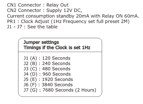
  • J1-J7: Time Set (Please see Schematic for Time Duration)
  • CN1: Relay Switch Connection Normally Open or Normally Closed
  • SW1: Timer Start
  • SW2: Timer Supply On/Off
  • PR1: 1Hz Frequency Set

Schematic

002_Schematic

Jumpers

002_settings

Pulse generator

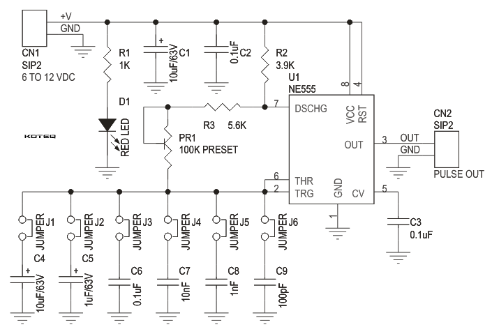
D009

Description

Pulse Generator project will generate a frequency in up to 180 KHz which can form a good test gear project.  This project is based on the classic 555 timer IC.

Specifications

  • Input : 5-12 VDC Max @ 40 mA
  • Provides Square Waves
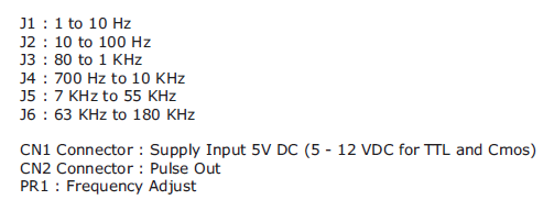
  • Range : Jumper selectable and preset tunable range of 1 Hz to 180 KHz
  • Power-On LED indicator
  • Berg connector for easy connection
  • Four mounting holes of 3.2 mm each
  • PCB dimensions 47 mm x 40 mm

Jumpers

jumper_settings

Schematic

D009 SCH

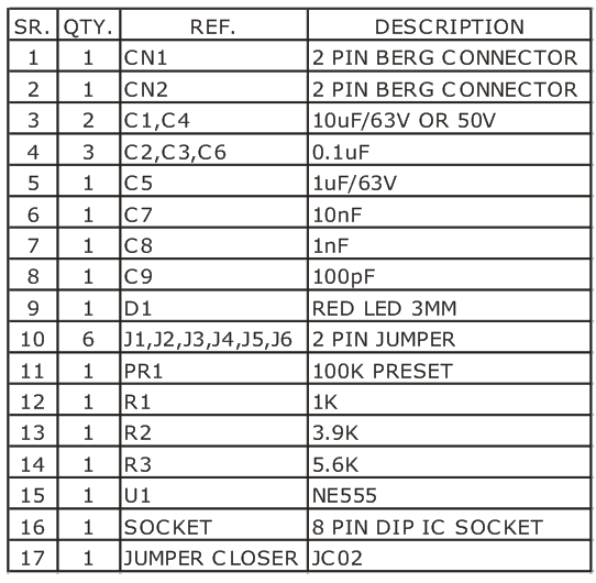
Parts

230V Blinking LED

photo


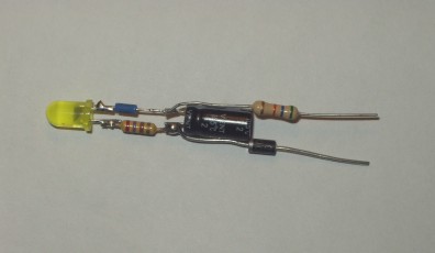
Attention: This Circuit is using 230V that is lethal. Please take appropriate precautions !!

Introduction

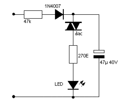
I needed a pulsating light for a certain signaling. Voltage was 230V. So I decided to make a simple circuit, consisted of a LED diode, two capacitors, two resistors, a diac and a diode.

Description

Activity of the circuit is extraordinarily simple. The capacitor charges by the diode and the resistor. When the voltage on the capacitor achieves 30V the diac “releases” the electrical tension and the capacitor empties thorough the diac, LED blinks. Time base is dependent from the capacitor and the resistor, which is in series with diode 1N4007. Capacitor must be at least for 40V.

Schematic

schematic


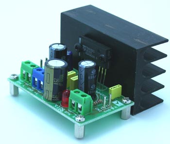
10W Stereo Audio Amplifier

10W_Stereo_Amplifier_PIC


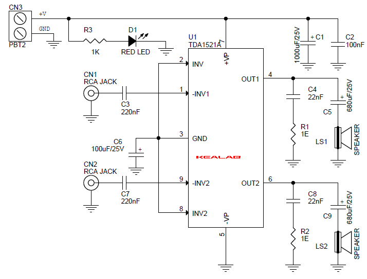
This project is a 10W Stereo Audio Amplifier based on TDA1521 IC.

Description

The project built around Philips TDA1521 IC, The project provides high quality audio 2X10W Audio output. The device is specially designed for mains fed applications, (e.g. Stereo TV Sound and Stereo Radio). The circuit designed for asymmetrical power supply systems.

Specifications

  • It has few external components
  • Input muted during power on and off
  • Low offset voltage between output and ground
  • Excellent gain balance between channels
  • Short circuit proof IC
  • Thermally protected
  • Supply 18V DC @ 3.5A
  • Output Power 2X10W
  • Voltage Gain 30dB
  • Frequency response 20Hz-20Khz
  • Input impedance 20K Ohm
  • Output load 8 Ohm
  • Recommended power supply 18V @ 3Amps

Schematic

10W_Stereo_Amplifier_SCHEMATIC


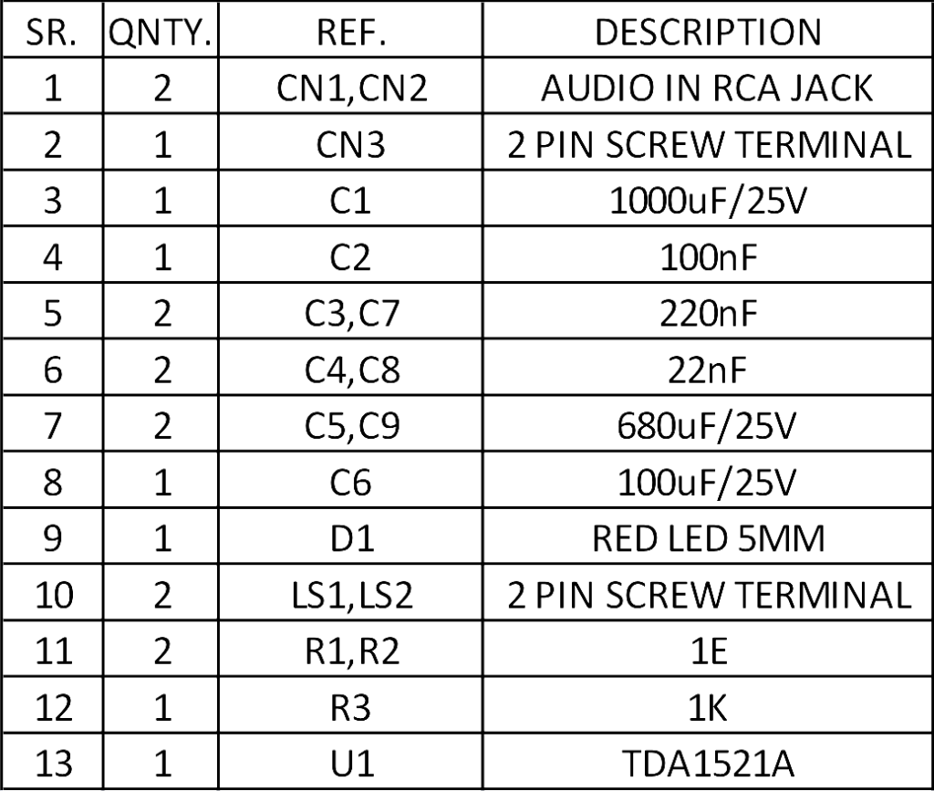
Parts

10W_Stereo_Amplifier_BOM

TDA152A Datasheet

Adjustable High/Low Frequency Sine wave generator

adjustable 122 khz sine wave generator

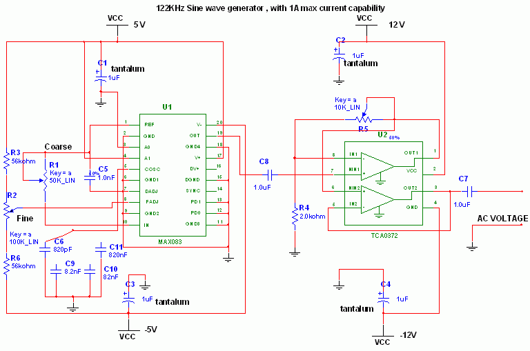
Adjustable High/Low Frequency Sine wave generator, low distortion.

Description

This circuit uses the versatile MAX038 function generator. Although in this circuit some of the advanced characteristics of this IC are disabled, you can generate Sine, Triangle, Square waves (adjusting A0 and A1 pins see datasheet on www.maxim-ic.com if you want other waves, use a switch).

The signal is amplified through a TCA0372 (from ONSEMI) Power opamp with current capability up to 1A and bandwitch up to 1 MHz.

I selected this particular frequency (122 Khz) because i needed a cheapo ESR-o-meter for my electrolytic capacitors to monitor their health as they have to discharge tens of amperes in less than 2 ms. At 122 KHz capacitive reactance is very low, and inductive reactance isn’t so high, so forcing a current (es 200mA, using a precision resistor) through a capacitor and reading AC voltage drop accross it gives me an estimation of ESR (Vdrop/current). Of course inductive and capacitive reactance are still present, but negligible.

Let’s back to the circuit.

Operation:

The 122 khz 2V p-p sine wave is generated by the MAX038 IC, its frequency can be calculated by the formula Freq (MHz) = Iin(uA) / C6 (pf) . Iin = 2,5V / R1 (25Kohm default). So the freq is 0,122 MHz . The resistor is for small adjustments, don’t go under 10000 Kohm or above 40000 Kohm because the accuracy will drop. If you want multifrequency just use the multiposition switch with 820 pF, 8,2 nF , 82nF , 820 nf for 122Khz range 12,2Khz range 1220 Hz and 122 Hz. Fine tuning can be done adjusting R2 , the frequency can vary from 1,7x (Vfadj = -2,4) to 0,3x (Vfadj = 2,4) of the main frequency (when fadj is at 0V).

The sine wave output is feed into a TCA0372 1/2 opamp to achieve a gain from 1 to 5 (2V p-p, 10 V p-p), adjust the potenziometer and into a TCA0372 2/2 opamp buffer stage also present on the same IC.

Important:

Adjusting the frequency needs a frequency counter, so this circuit should be used on conjunction with a freq couter. The max current is 1A, but i would suggesto to not go above 0,5A to remain accurate. Needs a computer power supply with 12V,5V,-5V,-12V,GND to be operated, if you don’t have one just use a multivoltage  mains transformer (15 watt is enough) diode bridges (low current 1-2 Amps), smoothing capacitors 10000uF 16V,  and voltage regulators such as LM7905 and LM7912.

TOP PCB Companies