Valentine LED Chaser

photo_1 (1)

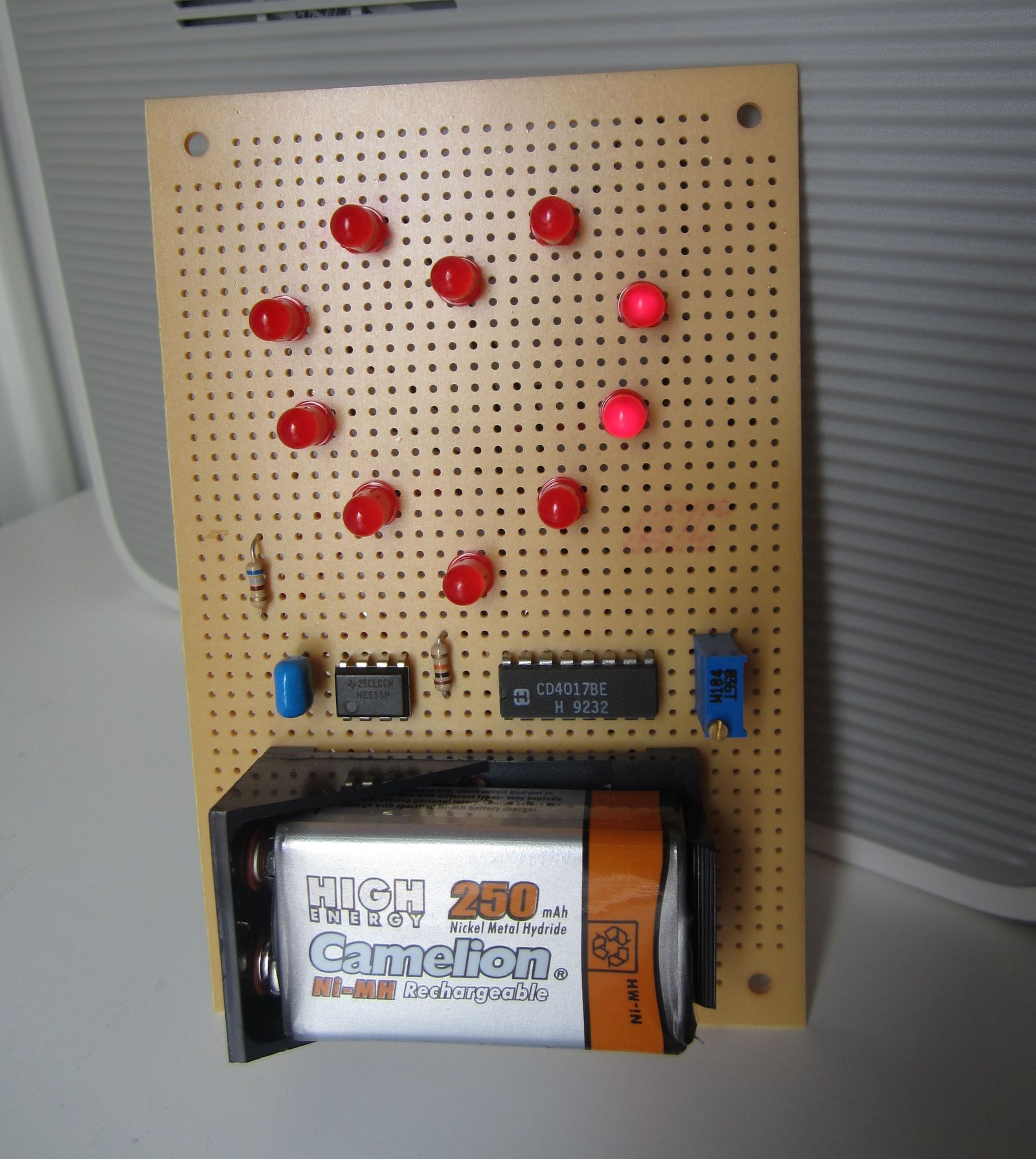
Every year at 14 February we celebrate the Valtentine’s day with our loved person. Usually we make a gift to each other to show our love to her/him. This can be a flower, chocolate or other stuff. Here we propose a different kind of gift to give her. That is a hand crafted LED chaser in a heart shape, so it’s has additional emotional value for her.

Description

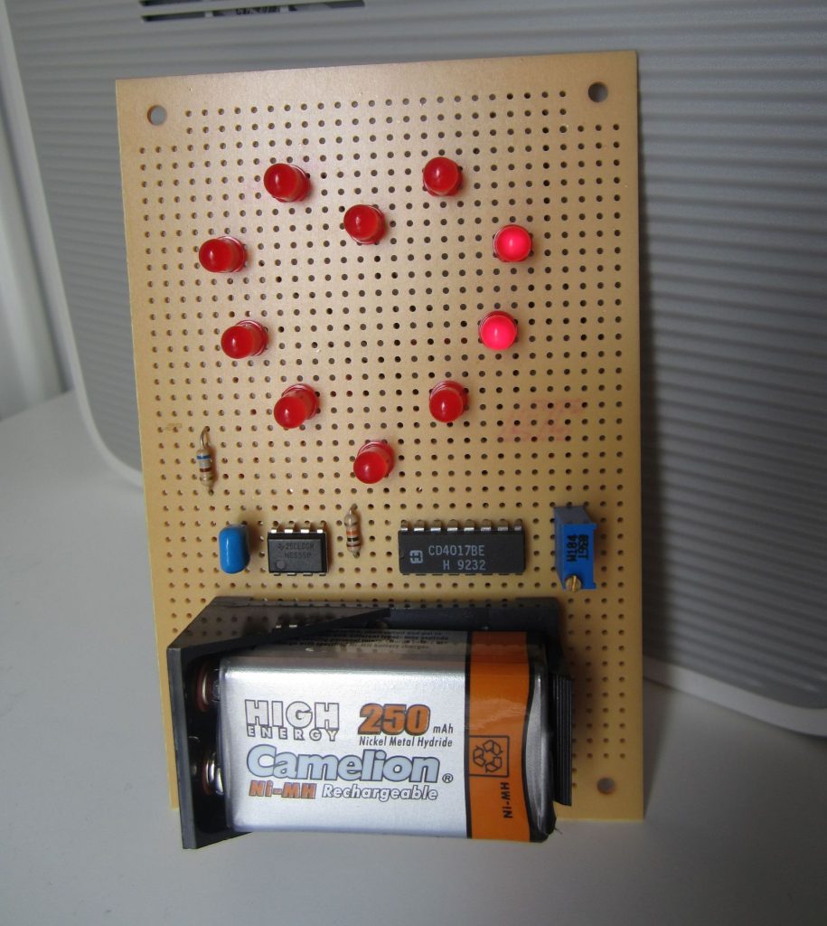
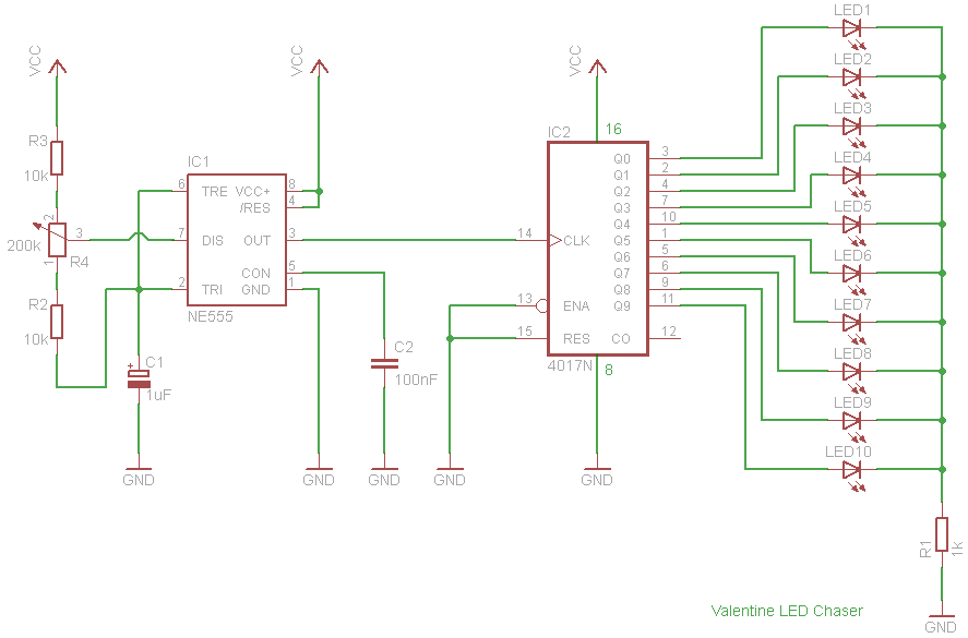
The led chaser is build on a perfboard using 10 leds, CD4017 decade counter, a 555 timer configured in astable mode and some additional components. The circuit is really simple. On the left we see the NE555 timer IC configured in astable mode, producing a squarewave which frequency is defined by the resistor array and C1 capacitor. Trimming R4 we are able to change the velocity of the running LEDs.

Schematic

The output of NE555 timer is feed to CLK of 4017 decade counter. So in practice decade counter is counting the pulses that NE555 produces and for each pulse one LED is lighting. On the next pulse the first LED is shut of and the next is light up. This continues until the last led is ON and the sequence continues from the first one.

So if you arrange the LED in a closed shape the LEDs will spin forever.

Video

PicoBuck – RGB LED Driver

photo_1

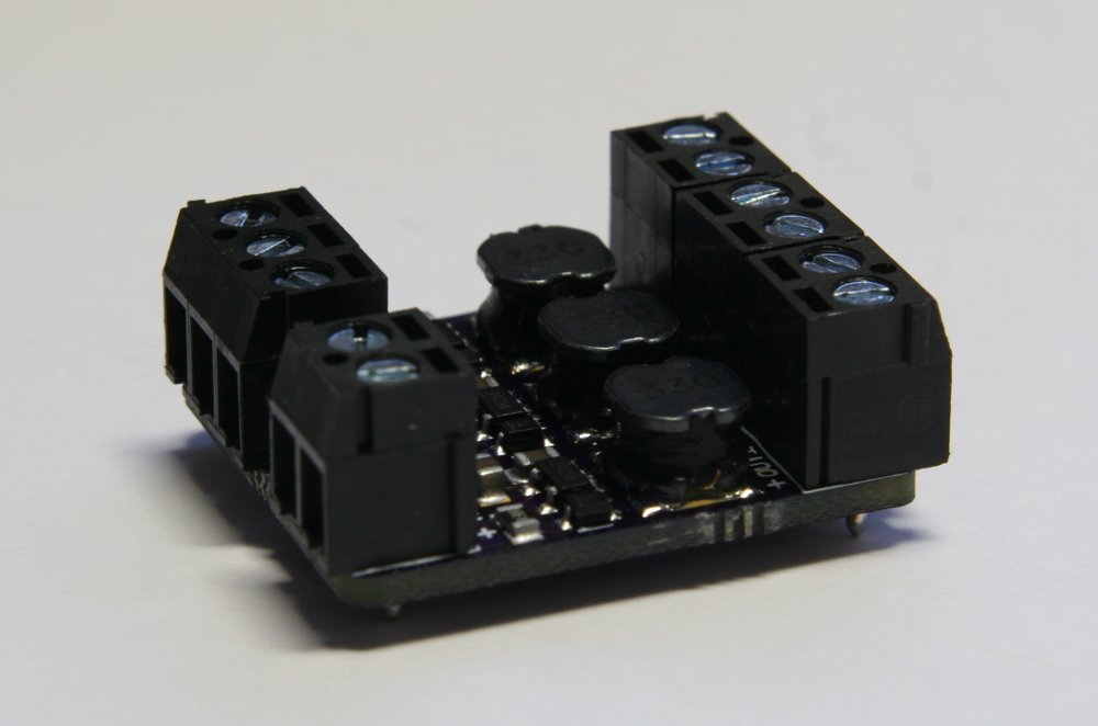
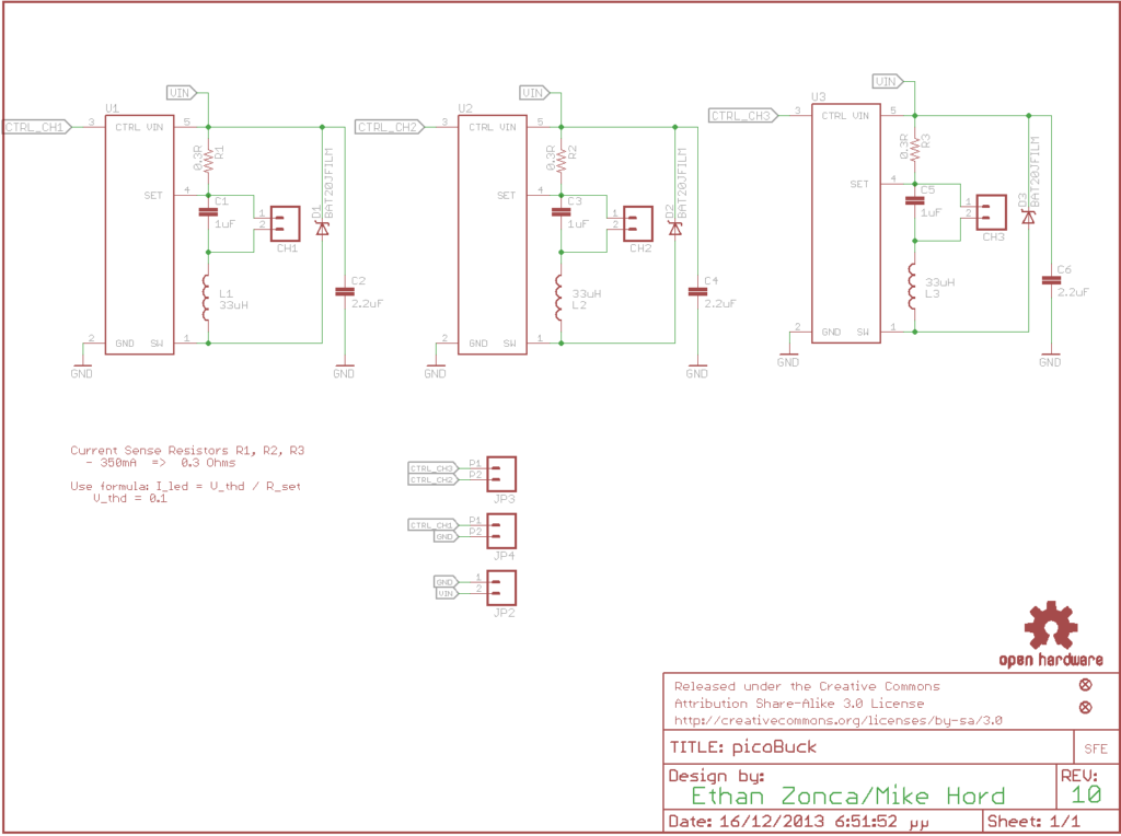
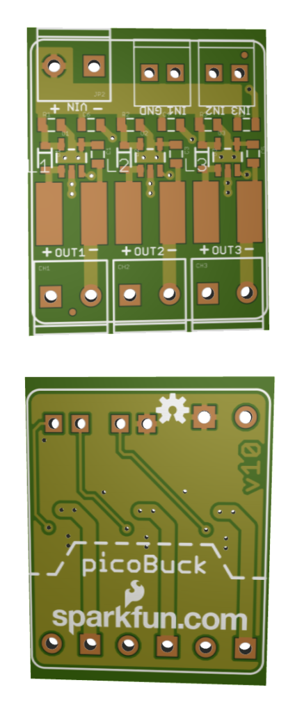
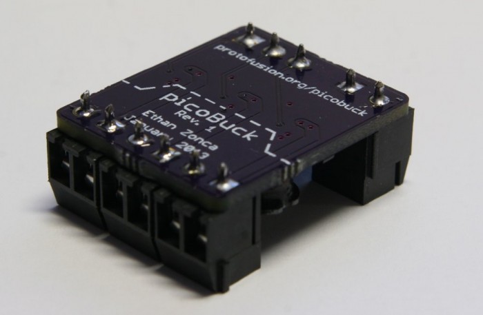
The PicoBuck is a small and inexpensive 3-channel LED driver. It employs constant-current buck driving which approaches an efficiency of 95% (theoretical). It’s based on AL8805 LED Lighting Buck Driver from Diodes Inc.

Description

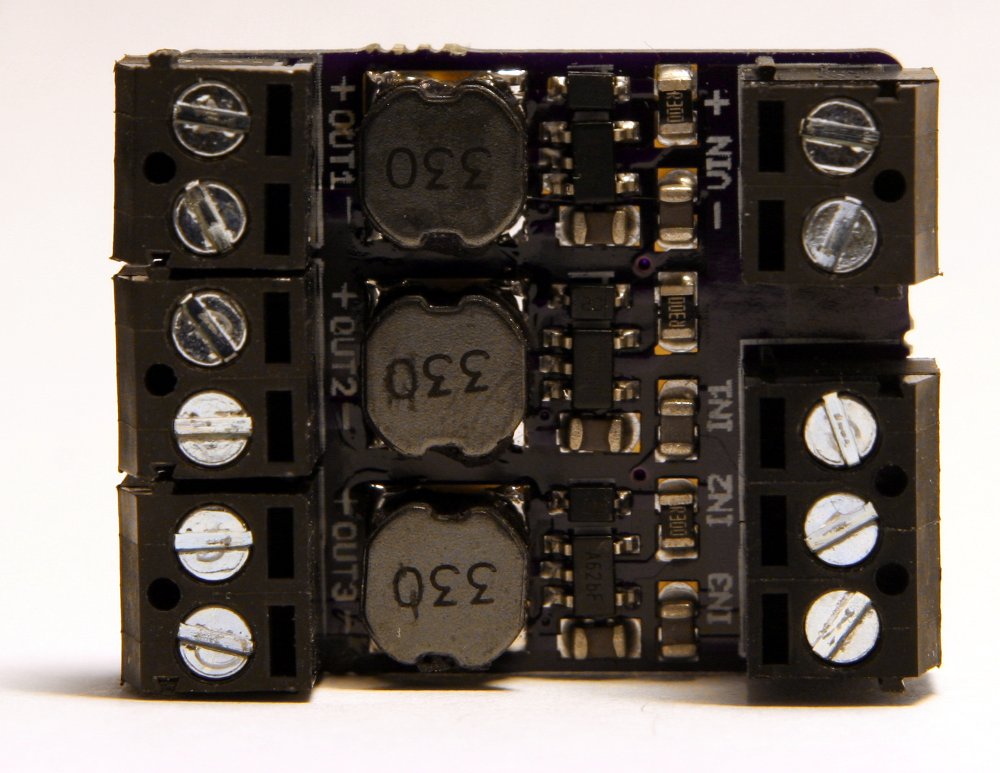
The PicoBuck supports a wide range of input voltages (6v to 20v) which may be connected to the VIN header. It has three inputs for each driver channel, labeled IN1, IN2, and IN3 which may be driven with standard 3.3v or 5v logic. LEDs are connected to the outputs of the driver, OUT1 through OUT3. Each channel of an RGB LED must be connected to the driver separately: this driver, like most buck drivers, does not support common-anode or common-cathode RGB LEDs.

Each channel of the PicoBuck can drive an LED at 350mA on the standard model. The driving current is set by a small current sensing resistor populated on the board. If you need to drive LEDs at higher or lower currents, just swap out the current sensing resistor to achieve your desired current. You can calculate the value of your current sensing resistor with the AL8805 spreadsheet.

photo_2

Usage

Digital Mode
To use digital drive mode, apply a standard 3.3v or 5v PWM signal to any of the 3 inputs. This method gives good brightness resolution over the entire range of brightness when using 8 to 10 bit PWM.

Analog Mode
To use analog mode, apply an analog voltage between 0v and 2.5v to any of the 3 inputs. This analog voltage controls how much current the LED is driven at, up to the current set by the current-limiting resistor. Note that the analog method is not effective for the last 20% of current—at this point, the current drops to zero.

Alternatively, you may employ a compound approach using analog dimming for high brightness and PWM dimming for low brightness. This method achieves optimal brightness resolution with minimal flicker, but is more challenging to implement in software.

Schematic

schematic

PCB

3D_PCB1

photo_37

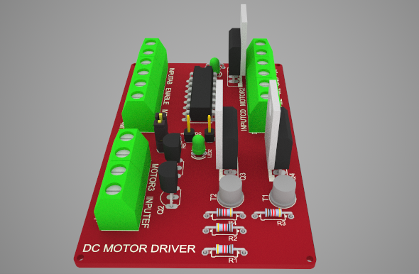
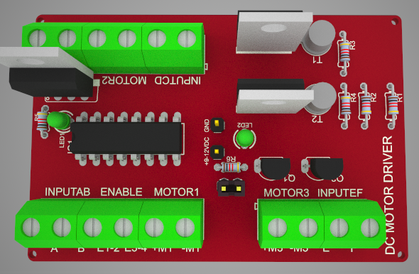
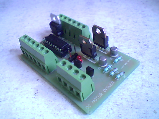
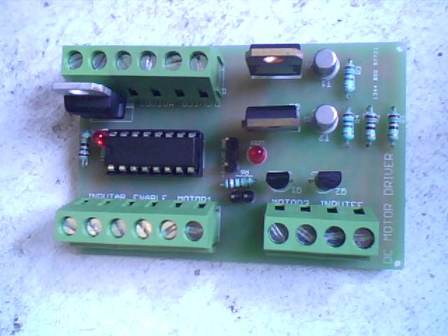
DC Motor Driver using L293D

DC_motor_driver_photo_4_th


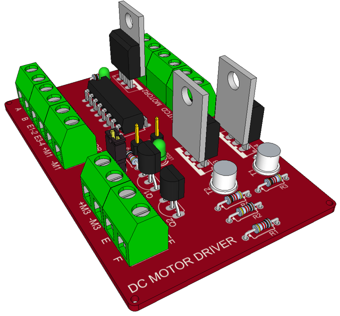
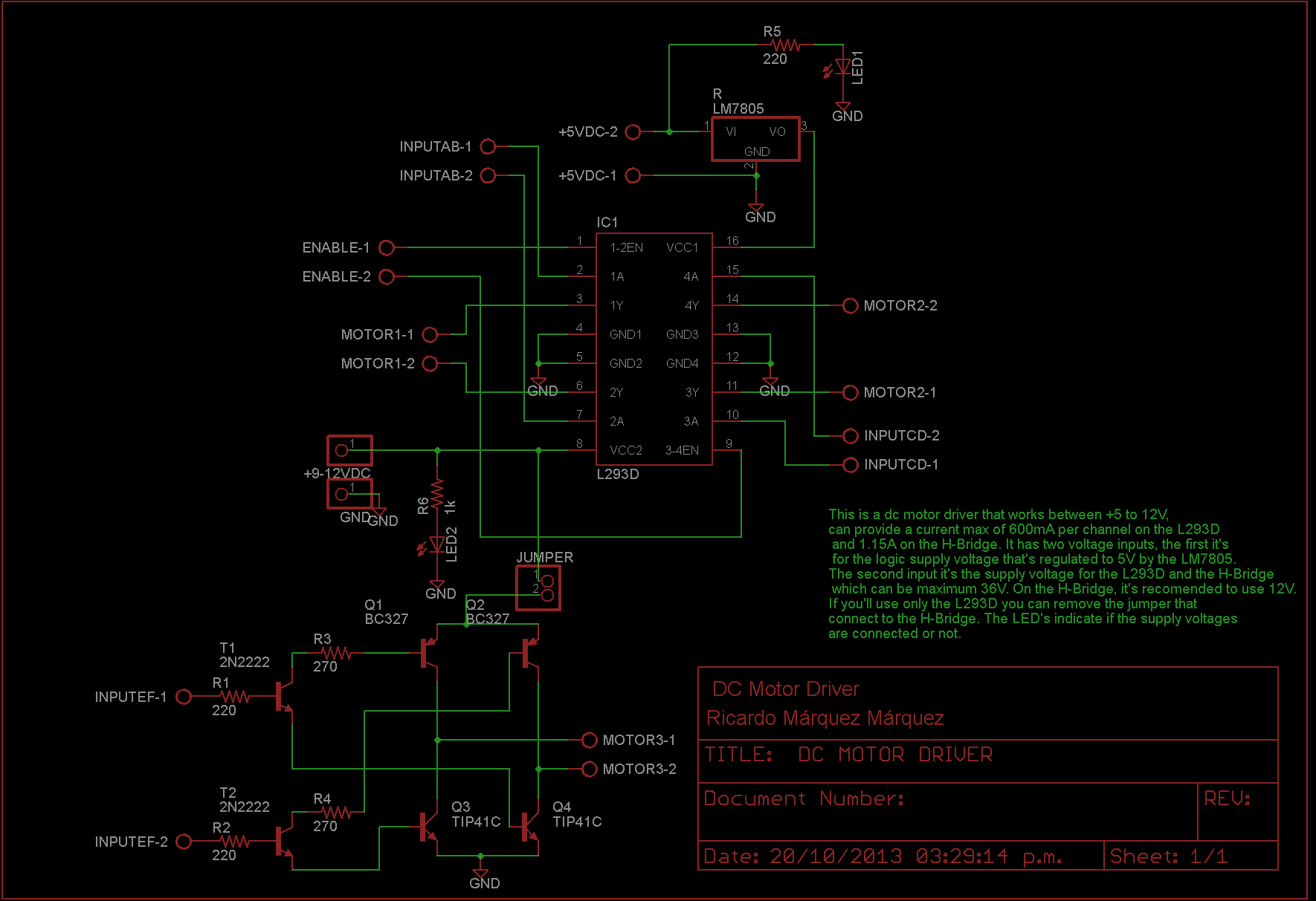
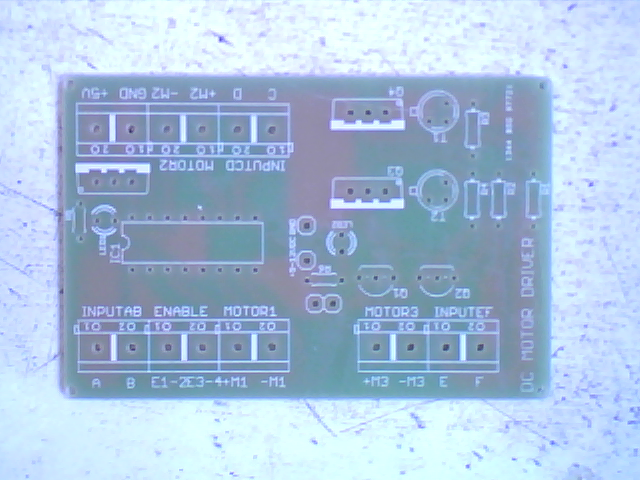
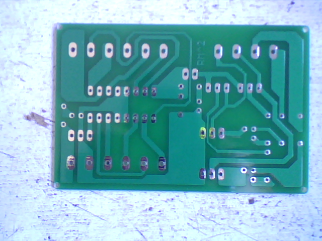
This project is a DC motor driver, suitable for motors of low or medium power. Allows controlling up to 6 motors or 3 motors if you want to control the rotation of the motors.

Description

The controller is build around the IC L293D that can provide 600mA per channel, and a H-Bridge designed with transistors NPN and PNP transistors, than can provide 1.15A per channel.

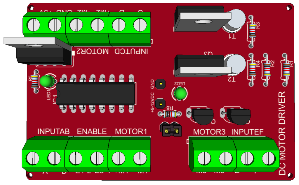
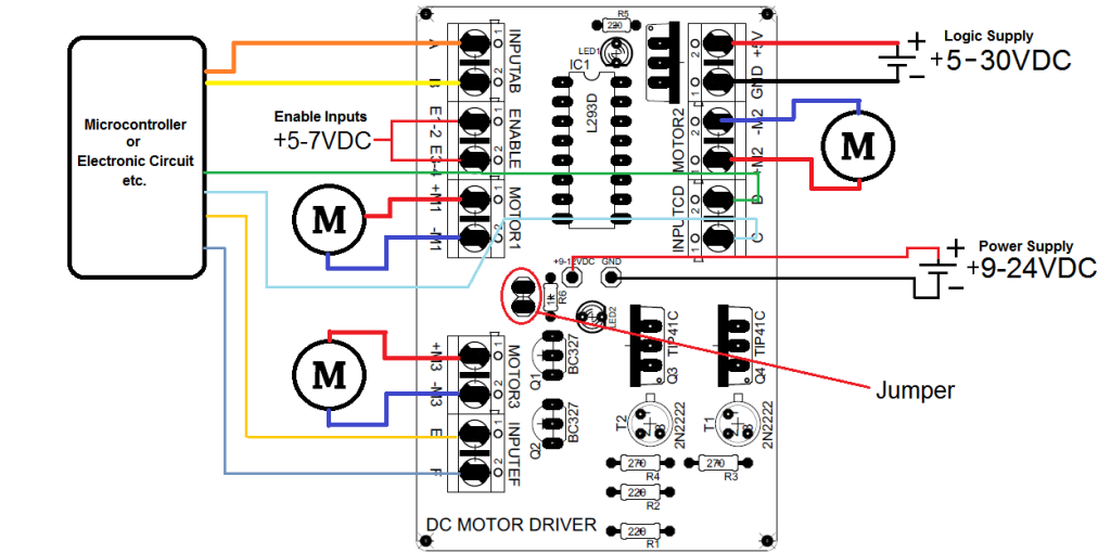
The controller has the following connections:

  • INPUTS (A, B, C, D ,E, F). These are receiving the analog or digital signals that can be sent for example, from a microcontroller.
  • ENABLE (E1-2, E3-4). These activate the inputs from the L293D. The supply voltage can’t be higher than 7V.
  • OUTPUTS (+M1, -M1, +M2, -M2, +M3, -M3). Here is where the motors should be connected.
  • +9-12V. Here’s where is connected a supply voltage that will give power to the motors. This input, gives voltage in the L293D and the H-Bridge, the supplied voltage have to be 36V max, but for the H-Bridge it’s recommendable to use 24V max. (In case you want to use only the L293D, you can remove the jumper).
  • +5V. This input receive the logic supply voltage for the L293D. You can connect a supply voltage higher than 5V because this input it’s connected to a voltage regulator (LM7805), but you not must to exceed 30V.

DC_motor_driver_photo_6

Schematic

Schematic

Connections

Example_Connection

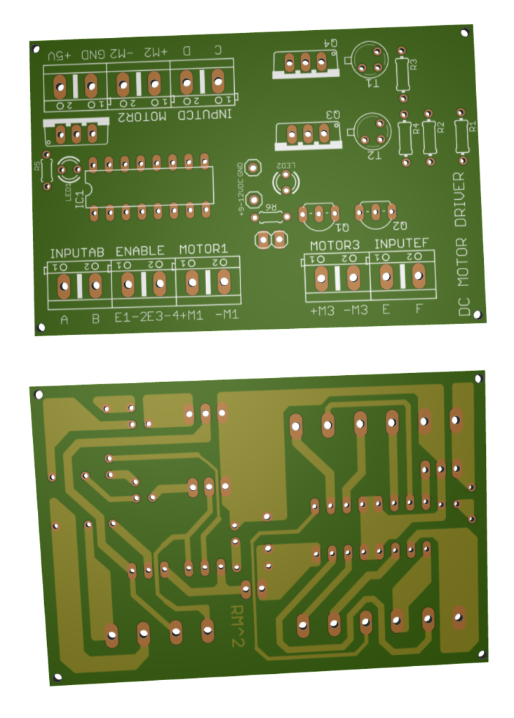
PCB

3D_pcb

3D PCB

DC_motor_driver_photo_1

DC_motor_driver_photo_2

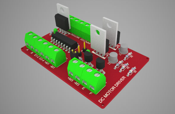
DC_motor_driver_photo_33D PCB Render

photo_1

photo_2

photo_3

photo_4

Super Flux RGB LED Controller

002

Introduction

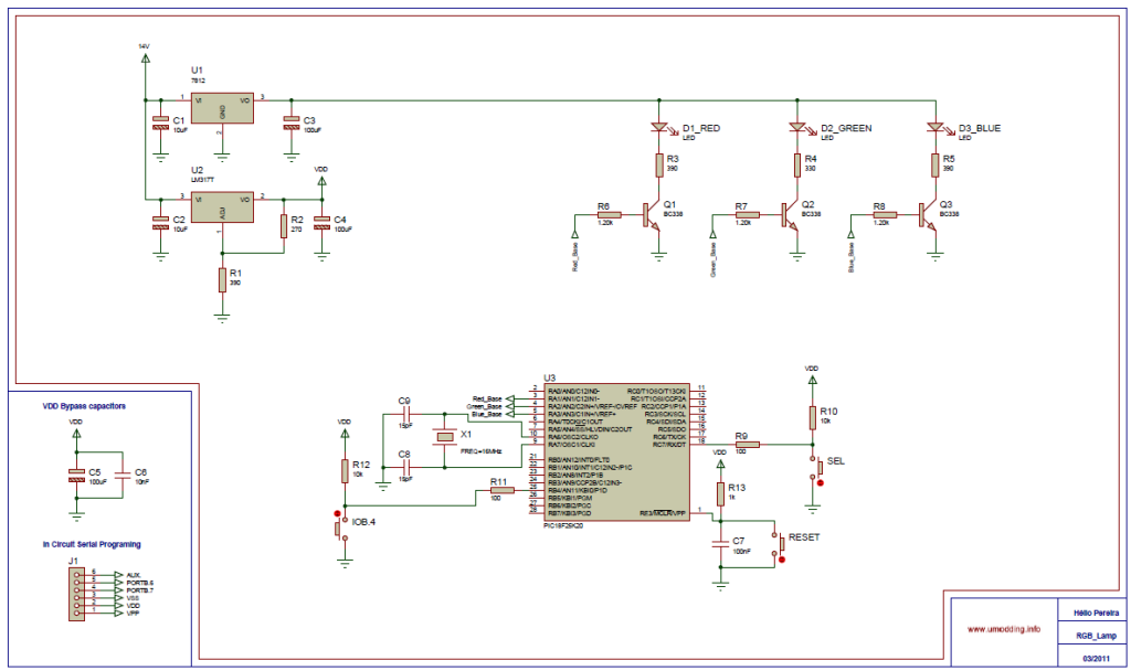
In this project it was used the “Piranha Super-flux RGB” Led of common anode, and the PIC18F25K20, in order to generate combinations of colors. It has two function modes, automatic that generate the color sequence that is stored in the μC memory, and the manual mode in which you can select one of the seven possible colors.

Schematic

Schematic

Firmware

The control of the RGB led is made with PWM(Pulse With Modulation), because PIC18F25K20 only have 2 PWM outputs (Hardware), I did the PWM by software to have 3 PWM outputs for that I use TIMER0 and for the Manual mode I use IOC(interrupt on change).

De-bounce

In this project I use push buttons to change between modes and to change the colors. But if we use the button as in the circuit (1) we have a problem. The problem with this configuration, due to the mechanical nature of any switch that may contains spring return action of some kind, there won’t be a clean transition from a state to another, but instead there will be a series of high and low states spikes. To solve that problem we have to implement a de-bouncing system, it can be done by hardware or software. We can use a RC delay circuit or it can be done with a schmitt trigger, but both ways will increase the price. So I done by software the de-bounce.

Example of code to do de-bounce:

code


It can be done in a different away but this way works for me.

PSU

I use a 7812 voltage regulator to keep the voltage stable in the RGB led and for μC I use an LM317 voltage Regulator. To calculate the output of LM317 I use this equation:

equation1

Led RGB

I use different resistor values on the RGB Led because which color have a different VF (Forward Voltage) in order to have the same LUX for each color. To calculate the resister I use these equations:

equation2

001


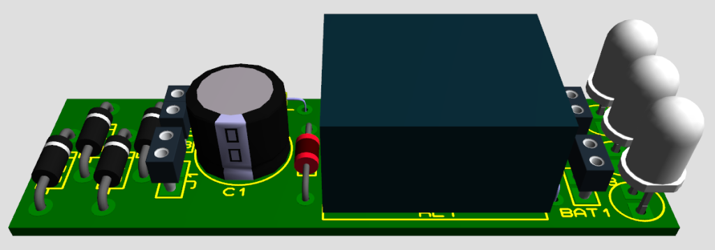
A Very Simple Power Failure Light

3D_Side_View

Introduction

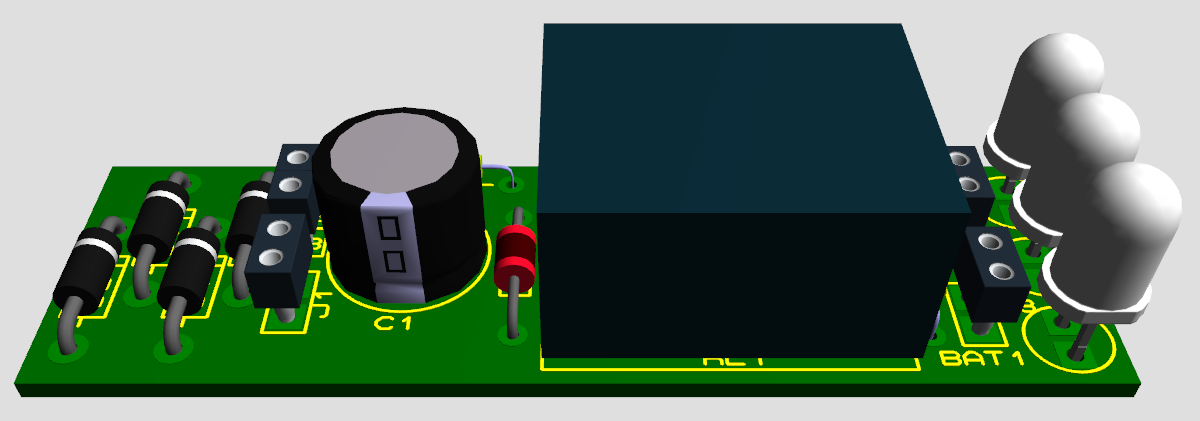
This is a very basic power failure lighting circuit based around a relay.

This simple circuit has many uses, from lighting up rooms and walkways in the case of a power failure, to monitoring and security uses.

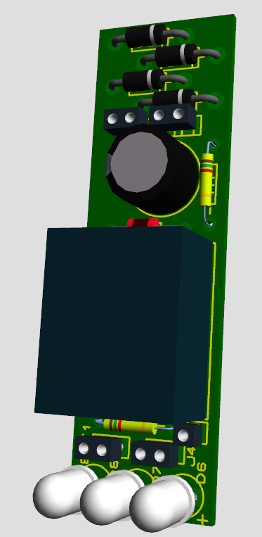
There are many different power failure circuits out there based on 555 timers or transistors but they all have different problems including limited input voltage, price and complexity, and poor backup power. This unit has been designed to work with mains power all the way down to 5 volts, and power 3 LEDs to provide light for a hallway or a child’s room in the event of power failure. The PCB includes many simple add-ons and modifications too. 

Specs 

  • Input Voltage Max: 240 Volts AC
  • Input Voltage Min: 5 Volts DC
  • Approximant Power Consumption: 450 mW

Schematic

Schematic

Explanation

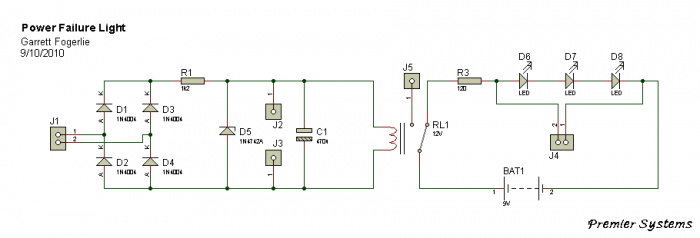
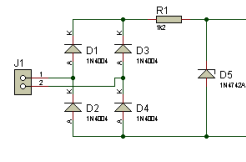
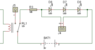
This circuit is connected to ac power through J1 then rectified to dc through D1D4. D5 is a 12 volt zener diode being used along with the resistor R1and the coil resistance of relay RL1 to regulate the input voltage to 12 volts and C1 is used to help smooth this power.

Schematic_1

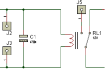
Alternatively a dc voltage of 5 volts or more can be connected directly to J2 and J3, positive to J2 and negative to J3; in this setup the circuit would not need J1, D1D5, and R1.

Schematic_2

The relay RL1 is a SPDT 5vDc relay and when power is applied to it, it opens the circuit with the LEDs so they are off as long as power is on if the power goes off, the relay closes the circuit and the battery BAT1 powers the LEDs D6, D7, and D8. In this circuit BAT1 is a 9 volt battery that powers the 3 LEDs through R3; however BAT1 can be many different batteries depending on your needs. J4 is also available in parallel with the LEDs to connect a buzzer or etc.

Schematic_3

You can also put a switch on one of the wires for BAT1 so you can turn it off so that you don’t drain it when the circuit is not being used.

3D_Verticle_View

Parts

1 R1 1.2k Ohm
1 R3 120 Ohm
1 C1 470uF
4 D1-D4 1N4004
1 D5 1N4742A
3 D6-D8 White LED
1 RL1* 12 Volt SPDT Relay
1 BAT1 9V
1 9V Battery Connector

*There are many different relays that can be used, some that even use next to no power.

Motorized Curtain with Remote control

OLYMPUS DIGITAL CAMERA


Introduction

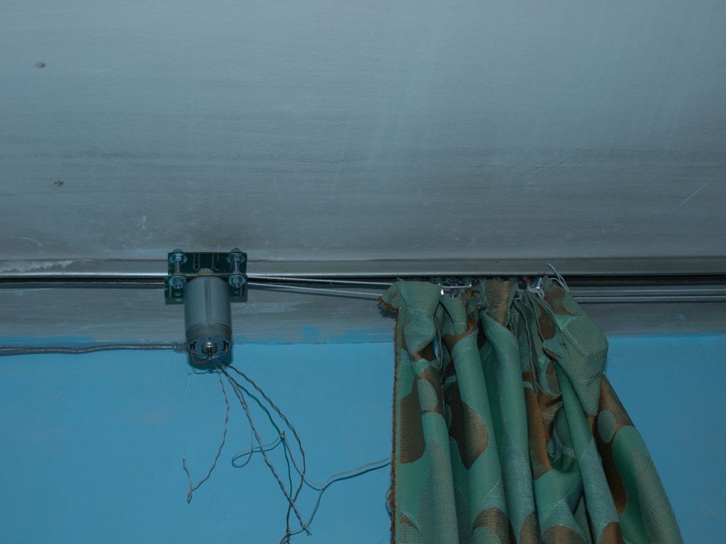
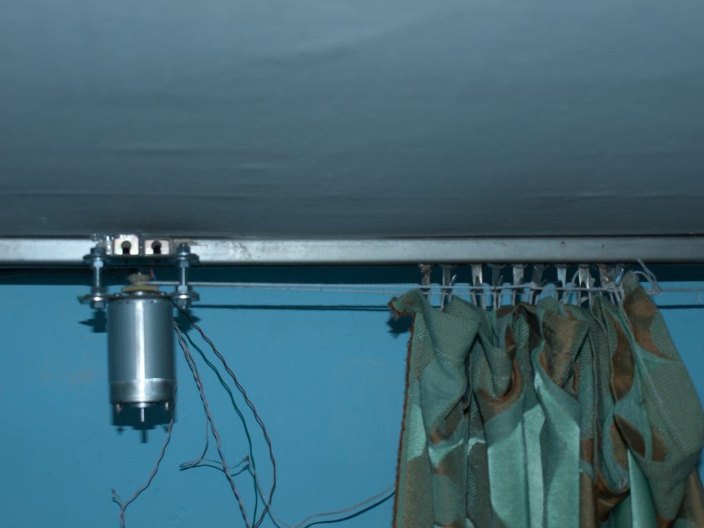
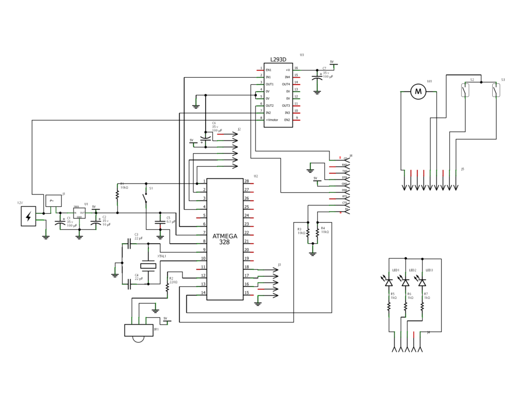
The project is “Motorized Curtain” with Remote control. It is made up of MCU ATMEGA328 with Arduino BootLoader, motor driver L293D ( i used L293B with external diodes, because i couldn’t find L293D ), IR Receiver TSOP 1738, DC Motor from an old printer and other small parts. To control it, i use IR remote control from a PixelView TV Tuner. The software allows moving the curtain from left to right and back, or on steps. On the last peg (of the curtain rail) is attached a small magnet, which interacts with the two reed contacts, placed on the two ends of the rail. The last peg is moved by a cord, which connects it to the motor on one side and a reel to the other.

Source Code is written on Arduino. I use NECIRRcv Libraries for decode code from IR Remote Control.

Schematic

Schematic

Photos

OLYMPUS DIGITAL CAMERA

OLYMPUS DIGITAL CAMERA

OLYMPUS DIGITAL CAMERA

OLYMPUS DIGITAL CAMERA

Digital Impulse Relay

photo_1

Introduction

In the first place, a relay is like a switch to a coil assembly. This switch is activated when electricity is applied to the coil. With a common relay, the electricity must be continuously applied to the coil to maintain the contacts, but the impulse relay “remembers” and only requires a momentary application of electricity. Stated differently, apply pulse of electricity to the coil to turn on the relay contacts, apply another pulse of electricity to turn off the relay contacts.

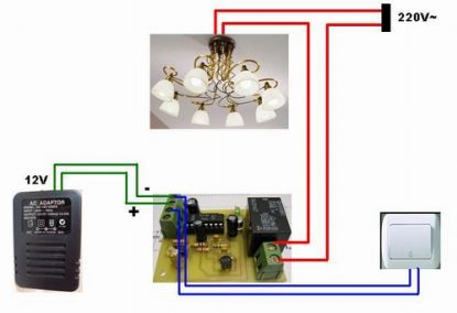
So, impulse relay use it for to turn on a lamp with pushbuttons and not toggle switches. What is really neat is connecting several momentary pushbuttons in parallel and placing them in different locations. I can turn on the lamp in one room, and turn it off from a different room, because it was the relay that was providing electricity to the lamp, not the switch.

Description

A digital impulse relay is a electronic circuit that mimics perfect the all functions of a impulse relay with ratchet mechanism: the first press to the button turns the relay on and the second press turns it off, and relay in the circuit operating room illuminates. Particularity of this circuit is that it can be used in a centralized system for home automation. Another advantage is lower price compared with that of the  impulse relay with ratchet mechanism. Digital impulse relay is immune to electrical noise, connection between buttons and circuit can be achieved with unshielded cable and any length.

Schematic

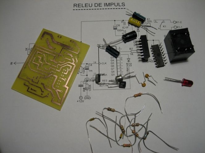
This circuit is operating the room illuminates. The basic component of the circuit is a IC1 (CD4017). Push buttons room are connected by normally wired to the circuit. All circuit is separately by optocoupler, which means that the circuit is immune to electrical noise that can come on cable that connects with push buttons.

First any button push put to GND the optocoupler IN. The output signal from optocoupler is amplified by transistor Q1 (BC557) together by C1, R3, R4 circuit.  The amplified signal is attack to clock pin 14 of decade counter IC1 (CD4017), the counter advances by 1, pin 2 goes high and relay is ON.Transistor Q2 (2N2222) connected to pin 2 of IC1 drives 12V relay. Diode 1N4004 (D1) acts as a freewheeling diode. LED1 indicate the ON/OFF status.

Second any button press, the IC1 advances by 1, pin 2 goes low, relay is OFF, and pin 4 goes high. If we connect by diode D2, pin 4 to Reset pin of CD4017, the counter is going back to the initial condition, and is ready to get another button press, to turn the relay ON.

The C2 – R6 component keep the Reset pin to +12V, when the circuit is powering, until the C2 loaded at 12V.

From transistor Q2 colector is IN/OUT for use in to microcontroller system (GSM remote control, WEB control, etc.). When use as IN, microcontroller system can put to GND Q2 colector, and relay is ON. Or the colector is use as OUT, signal obtained say the microcontroller system, if the relay is ON or OFF.

The power supply for the circuit is DC 12V. In standby, when relay is OFF, digital impulse relay consume 0V. Otherwise, when relay is ON, consume depend of 12V relay current.
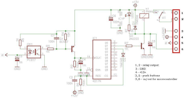
Schematic

Installation

photo_2

Parts List

photo_3

Infrared Toggle Switch for Home Appliances

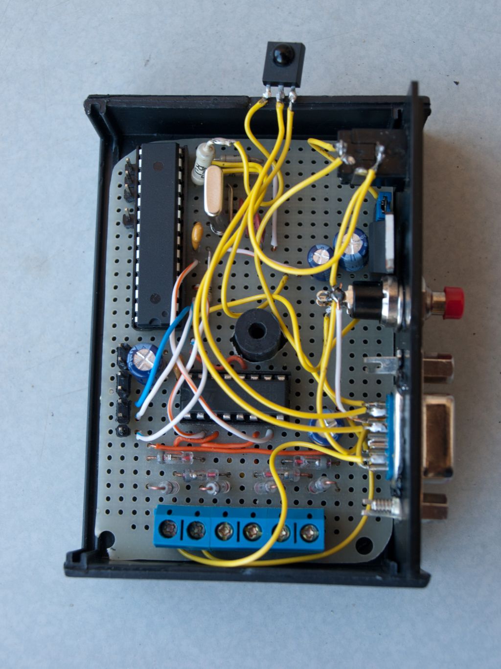
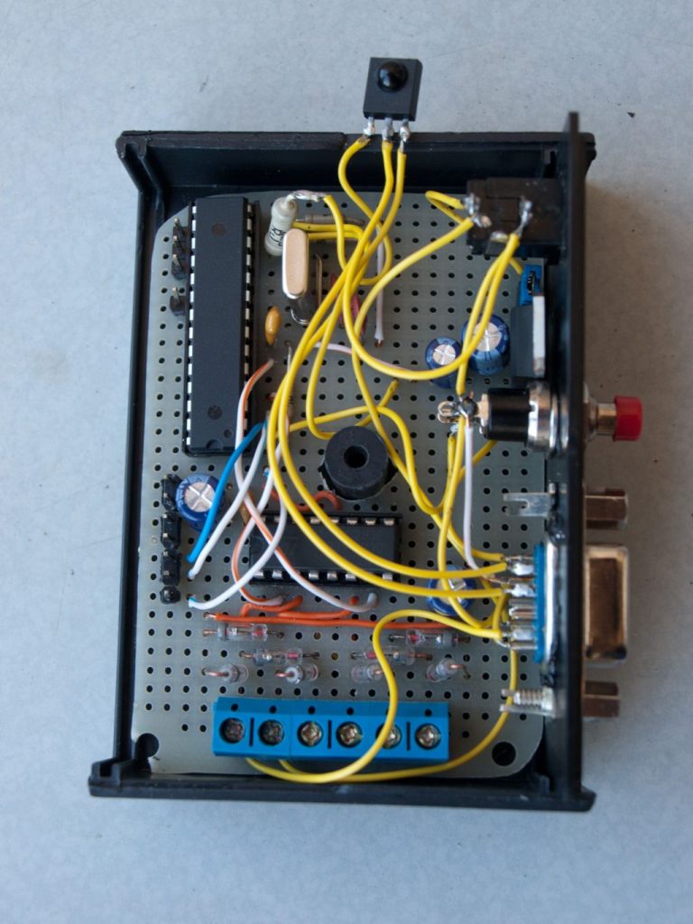
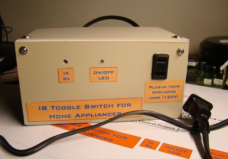
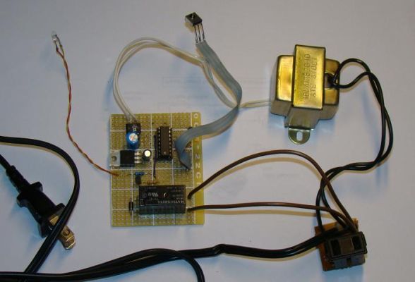
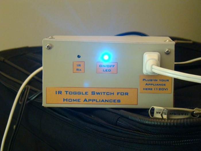
My IR toggle switch enclosed inside a box

Introduction

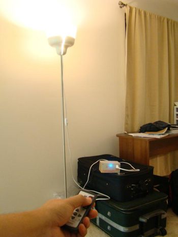
The infra-red (IR) toggle switch project described here is aimed to provide control mechanism for electrical appliances that do not have remote operation features. The goal is to construct a black box where you can plug-in your 120V AC appliance and control ON and OFF operations with any modern IR remote control devices.

Modern IR remote controls generate modulated pulse train of 38KHz frequency when any key on the remote is pressed. With the use of capacitive filtering we will convert the stream of pulses into one pulse regardless of the key entered. This way, we will be able to toggle a relay switch with any key pressed on the remote. This project has been tested with varieties of IR remote control devices like that for TV, DVD, digital camera, etc., and it worked well.

Schematic

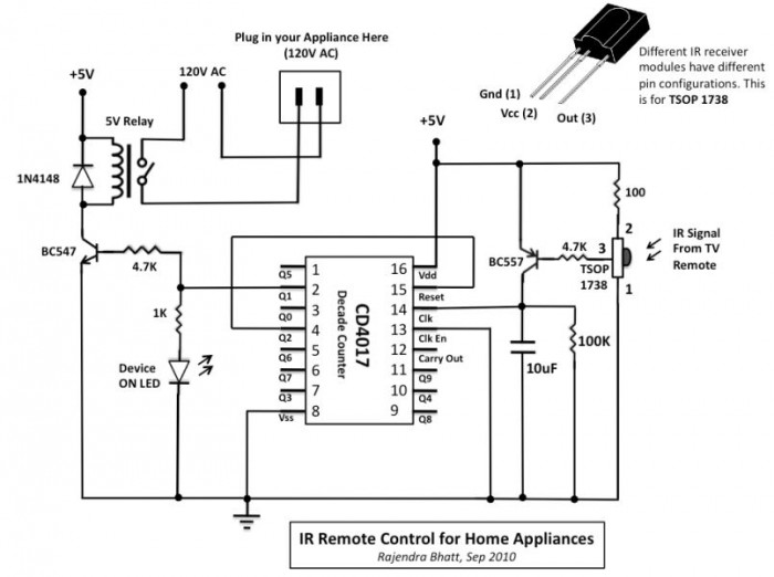
The TSOP 1738 IR receiver module detects the 38KHz input pulses received from the IR remote control device. Under stand-by condition, the output pin of the IR module is at logic High, and when it detects the train of pulses, they appear at its output. The output from IR receiver is fed to a PNP transistor (BC557) with a series base resistor of 4.7K. At the collector of the NPN transistor, the train of pulses will be inverted. There is a 10uF capacitor and 100K resistor connected from the collector to ground. The function of capacitor is to convert the train of pulses into a single pulse, and the resistor is to provide the discharge path for the capacitor.

So lets see what happens when a key on the remote is pressed. During standby, the output of IR receiver module is High, so BC557 is cut off. The capacitor is fully discharged, and the collector of BC557 is at ground. When a key is pressed on the remote, the train of pulses arrived at the base of BC557 turns it ON and OFF very fast. When it is ON, the capacitor gets charged through the collector current of BC557, and when it is OFF, the capacitor starts to discharge  through 100K resistor. But the train of pulses is so fast (38000 pulses per second) that the capacitor doesn’t get chance to discharge. So, the bottom line is, every time a key is pressed from the IR remote, a positive going clock pulse is generated at the collector of BC557 transistor. 
Schematic

Next comes CD4017, a decade counter. It counts low-to-high going pulses up to 10 that are arrived at its CLK pin (14) and pulls the corresponding output (Q0-Q9) High. When it is just turned on, Q0 goes High, and when it gets a first low-to-high pulse (when a key is pressed from the IR remote) at CLK i/p, Q0 goes Low and Q1 goes High. Q1 output is connected to a LED through a current limiting resistor to indicate the ON/OFF status. The Q1 output is also used to drive a relay switch through a NPN transistor (BC547). I used 5V DC relay that requires about 70mA current from 5V source to turn ON. This current is provided by BC547. 

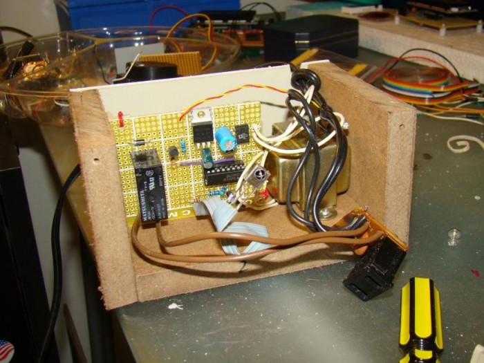
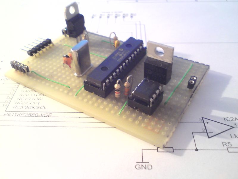
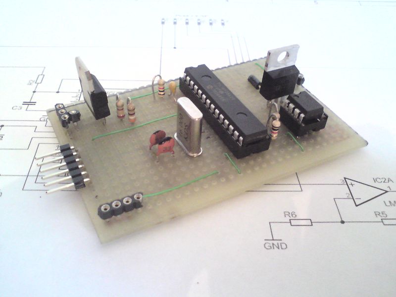
Complete circuit before putting inside the box
photo_3
Packing inside a box for safety as it deals with 120V AC.

Now, lets see what happens when a key is pressed again. The counter advances by 1, Q1 goes Low (relay is OFF), and Q2 goes High. If we connect Q2 to Reset input of CD4017, the counter is going back to the initial condition (Q0 High, Q1 and all others Low), and is ready to get another key press signal to turn the relay ON. This way the switch is toggled every time a key is pressed from the remote.

Power Supply

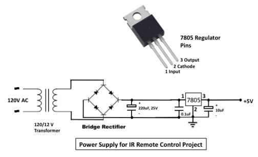
The power supply for the circuit is provided through a 5V regulator IC LM7805. A 12V step-down transformer with a bridge rectifier and a capacitor filter provides an unregulated DC input to LM7805. The regulator IC provides a constant 5V supply for the circuit.

power_supply_schematic

Be careful on the output side of the relay that connects to 120V AC line. A  reversed biased diode parallel to the relay input is for back emf protection.

Switch in Operation

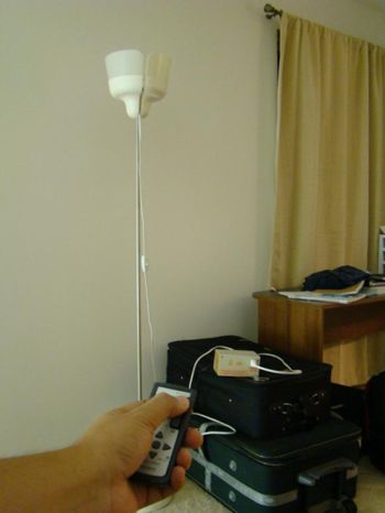
Below are some snapshots showing the IR toggle switch in operation.

Device OFF
Device OFF
Device ON
Device ON

photo_6


PIC PWM Fan controller

photo_01

Description

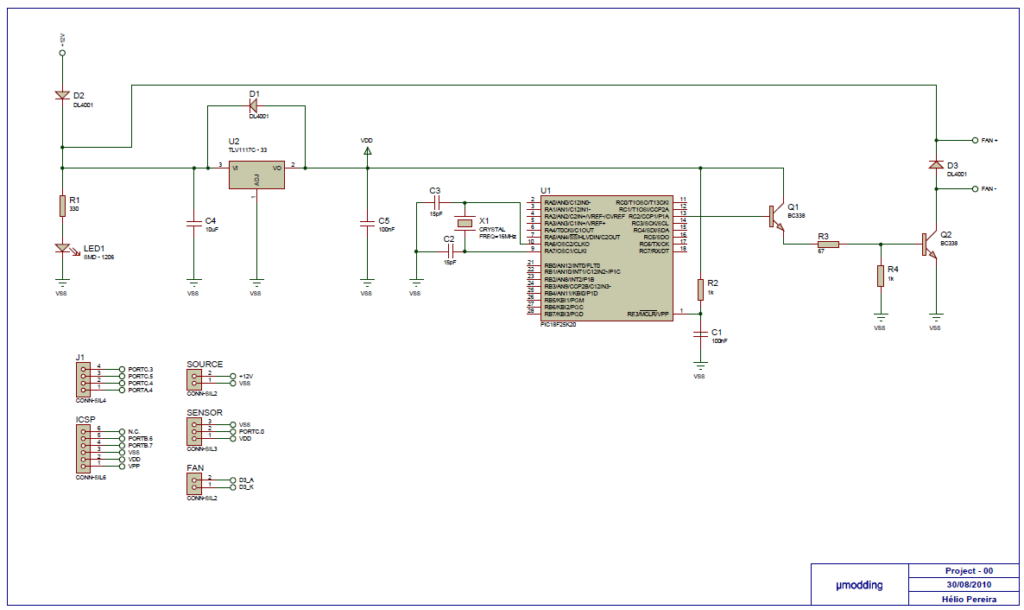
This project it´s based on a PIC18F25K20, with the purpose of control a FAN with PWM (Pulse with Modulation). It offers a variable speed control, low acoustic noise, reliability, long lifetime, low power consumption, protection features. The MCU get the temperature from the sensor (D18B20), and after will do a conversion Celsius degrees and then it´s generated a PWM on PORTC.2 with 6 different levels.

PWM

TEMPERATURE

15%

<= 49°

30%

50°

40%

51°

50%

52°

75%

53°

100%

>54°

After the signal goes to Q1 (BC338) in order to control the duty cycle in the fan. I had to use two transistors to have an Ic on Q2 to be enough to activate the fan. Because the MCU only generate a maxim of 3.6V on which output, and 15% of 3.6V is 0.5V to polarize Q1 we need 0.7V.

How to calculate the Q1 and Q2:

formula

You will be able to control the FAN between 5V and +/-12V.The BC338 have a current load of 800mA that is value of a fan can have, you can use two or more fans as long the current load isn´t more than 800mA. The output of MCU connect to the Q1 and Q2 it works like a switch, the D3 it´s for protection from the magnetic field in the inductors from the FAN, without the D3 when you turn off the system the current will be discharge to the Q2 and could damage it.

Connectors

J1 Expansions PORTS
Source 12V
Sensor D18B20
FAN Connect the FAN
ICSP To program with PICKIT2

photo_02

Photo of the prototype on perfboard

Schematic

Schematic

Super Bright Led Flasher

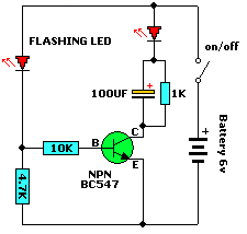
Schematic

Description

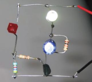
This is a novel flasher circuit using a single driver transistor that takes its flash-rate from a flashing LED. The flasher in the photo is 3mm. An ordinary LED will not work. The flash rate cannot be altered by the brightness of the high-bright white LED can be adjusted by altering the 1k resistor across the 100u electrolytic to 4k7 or 10k.

The 1k resistor discharges the 100u so that when the transistor turns on, the charging current into the 100u illuminates the white LED. If a 10k discharge resistor is used, the 100u is not fully discharged and the LED does not flash as bright. All the parts in the photo are in the same places as in the circuit diagram to make it easy to see how the parts are connected.

Photo

photo


TOP PCB Companies