
Description
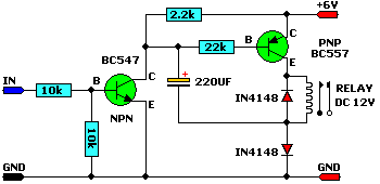
This circuit allows a 12v relay to operate on a 6v or 9v supply. Most 12v relays need about 12v to “pull-in” but will “hold” on about 6v. The 220u charges via the 2k2 and bottom diode. When an input above 1.5v is applied to the input of the circuit, both transistors are turned ON and the 5v across the electrolytic causes the negative end of the electro to go below the 0v rail by about 4.5v and this puts about 10v across the relay.

Description
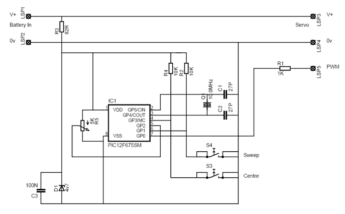
This is a simple servo tester which will comprehensively test the capabilities of almost any modern servo. It has two pushbuttons, CENTRE and SWEEP and a potentiometer which works as follows:
- CENTRE Does exactly that, centers the servo, afterwards the potentiometer determines position.
- SWEEP Sweeps the servo back and forth at a rate determined by the potentiometer setting.
The PIC uses its internal timer to set up a constant frame duration of 20ms and the on/off ratio is set by the user.
Parts
R1 = 1K
R2 = 10K
R3 = 82R
R4 = 10K
R5 = 5K potentiometer
C1 = 27pF
C2 = 27pF
C3 = 100nF
D1 = 4,7V zener diode
Q1 = 10MHz crytal
IC1 = PIC12F675
Panel


Description
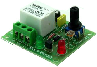
Dark Sensitive switch project based on single BC547 transistor, Relay operates when light that falls on the LDR, goes below a set point. It’s very simple and low cost dark sensitive switch required few components.
Features
- Input : 12 VDC @ 55 mA
- Relay output : NC – C – NO
- Onboard preset to set the level
- Power-On LED indicator
- Relay On LED indicator
- Screw terminal connector for easy relay output connection
- Four mounting holes of 3.2 mm each
- PCB dimensions 44 mm x 40 mm
Schematic

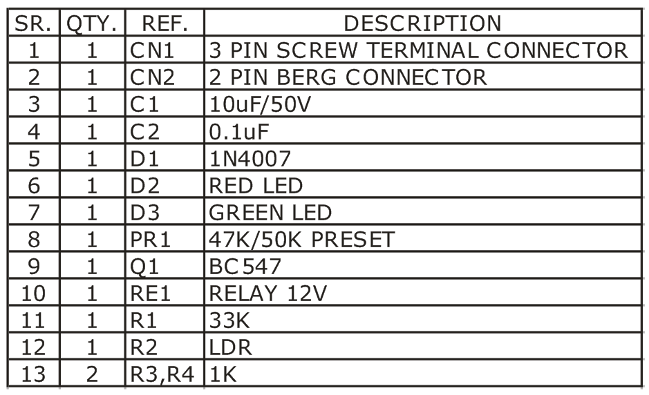
Parts

Description
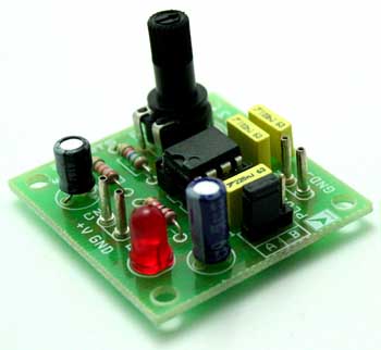
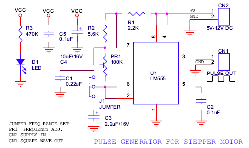
The 555 Stepper Pulse Generator kit will help you with the pulse required to drive your favorite DC Servo Motor application. This kit uses the famous 555 timer IC for generating the Stepping Pulse.
- Input – 5 – 12 VDC @ 25 mA
- TTL/CMOS interfaceable
- Jumper selectable two speed operation
- Onboard preset to vary the duty cycle
- Power-On LED indicator
- Terminal pins for easy interfacing of the kit
- Four mounting holes of 3.2 mm each
- PCB dimensions 39 mm x 37 mm
Schematic

Description
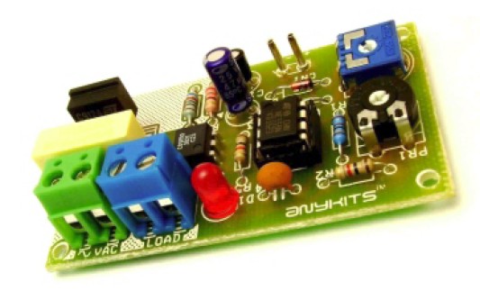
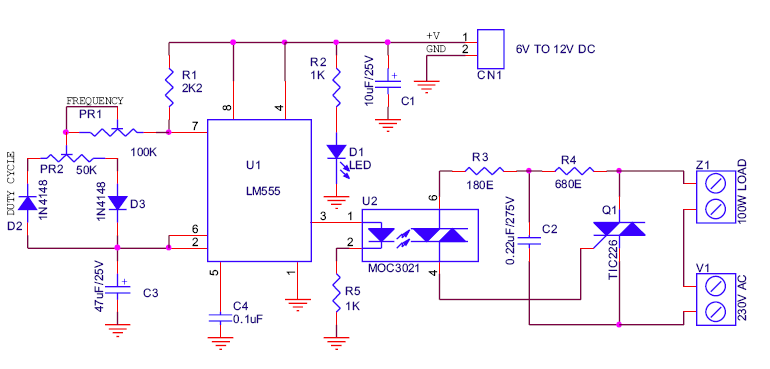
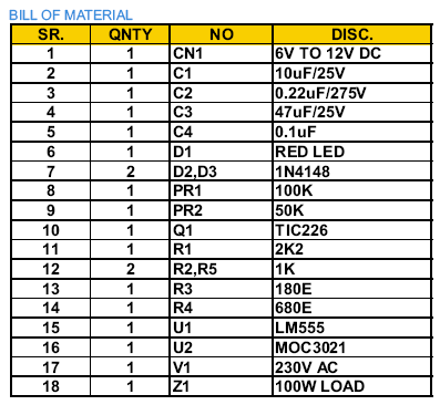
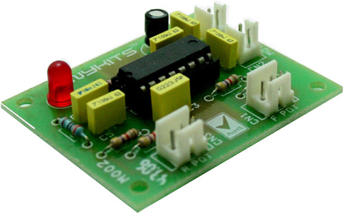
200W Lamp Flasher kit is used to flash lamps, bulbs and halogen lamp to give your product that attracting look.
- Input supply – 6 ~ 12 VDC
- Output – upto 200 W lamp / bulb load
- Optically isolated Mains supply
- Onboard preset to adjust the frequency (speed) of flashing (1 Hz to 5 Hz)
- Power Battery Terminal (PBT) for easy input 230 VAC mains and load connection
- Terminal pins for connecting DC power supply
- Four mounting holes of 3.2 mm each
- PCB dimensions 36 mm x 68 mm
Schematic
 Parts
Parts

Description
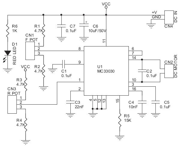
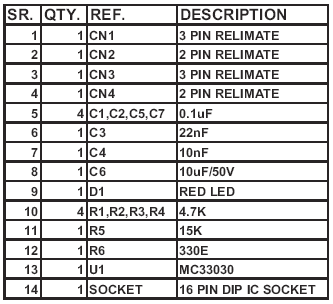
DC Servo Motor Driver kit, designed using MC33030 IC, is the fastest and low cost way of getting your DC Servo Motor up and running.
- Input – 12 VDC
- Output – can drive upto 1 A Load
- Overcurrent shutdown, overvoltage shutdown
- Programmable reference input
- Power-On LED indicator
- Relimate connector for interfacing the kit
- Four mounting holes of 3.2 mm each
- PCB dimensions 45 mm x 54 mm
Schematic
Parts
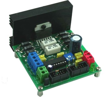

Description
High Current Bipolar Stepper Motor Controller kit is based on chopper drive. Chopper drive is a method of providing a constant current source to a device. Chopper drive allows for use of higher voltage power supply for better performance and higher speed. It is uses SGS Thomson’s L297 and L298 controller IC’s.
- Logic supply – 5 VDC @ 300 mA
- Motor Supply – 8 to 30 VDC
- Connection via 10-pin Box Header for easy interface with any microcontroller development boards
- External or internal voltage reference option via jumper
- Onboard preset for current adjustment
- High speed switching diodes for L298 IC protection
- Power-On LED indicator for both the supplies
- Power Battery Terminal (PBT) for easy supplies and motor connection
- Heat sink included
- Four mounting holes 3.2 mm each
- PCB dimensions 74 mm x 71 mm
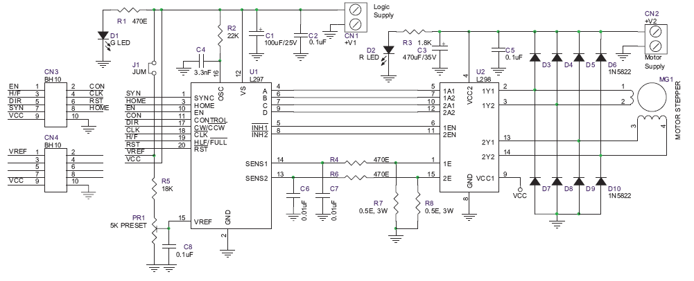
Schematic

Description
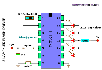
General Description of the following circuit. This circuit is based around HT2050 manufactured by HOLTEK semiconductors. It is a low cost, low-power C-MOS LSI designed for lamp and LED flash driver. It requires minimum external components.You can operate it with just two AAA cell or 3v Battery.Circuit has five flash outputs with 10mA drive capability that can implement random or sequence flashing function controlled by one option pin.It only requires one external resistor for typical application. It is very suitable for the use of the flash products such as disco glasses, disco hat, gift card, Xmas decoration and so forth.

Description
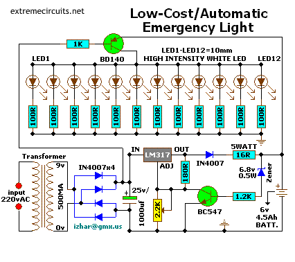
Here is a white-LED-based emergency light that offers the following advantages:
- It is highly bright due to the use of white LEDs.
- The light turns on automatically when mains supply fails, and turns off when mains power resumes.
- It has its own battery charger. When the battery is fully charged, charging stops automatically.
The circuit comprises two sections: charger power supply and LED driver.The charger power supply section is built around 3-terminal adjustable regulator (IC1) LM317, while the LED driver section is built around transistor BD140(T2). In the charger power supply section, input AC mains is stepped down by transformer to deliver 9V, 500mA to the bridge rectifier, which comprises diodes (IN4007x4). Filter capacitor (25v/1000uf)eliminates ripples. Unregulated DC voltage is fed to input pin 3 of IC1 and provides charging current through diode IN4007(D5) and limiting resistor (16ohm)R16. By adjusting preset 2.2K(VR1), the output voltage can be adjusted to deliver the required charging current. When the battery gets charged to 6.8V, zener diode conducts and charging current from regulator (IC1) finds a path through transistor BC547(T1) to ground and it stops charging of the battery. The LED driver section uses a total of twelve 10mm white LEDs.
All the LEDs are connected in parallel with a 100-ohm resistor in series with each. The common-anode junction of all the twelve LEDs is connected to the collector of pnp transistor T2 and the emitter of transistor T2 is directly connected to the positive terminal of 6V battery. The unregulated DC voltage, produced at the cathode junction of Bridge(Diodes), is fed to the base of transistor T2 through a 1k resistor. When mains power is available, the base of transistor T2 remains high and T2 does not conduct. Thus LEDs are off. On the other hand, when mains fails, the base of transistor T2 becomes low and it conducts. This makes all the LEDs (LED1 through LED12) glow. The mains power supply, when available, charges the battery and keeps the LEDs off as transistor T2 remains cut-off.
During mains failure, the charging section stops working and the battery supply makes the LEDs glow. Assemble the circuit on a general-purpose PCB and enclose in a cabinet with enough space for battery and switches. Mount the LEDs on the cabinet such that they light up the room. A hole in the cabinet should be drilled to connect 230V AC input for the primary of the transformer. I have tested the circuit with twelve 10mm white LEDs.You can use more LEDs provided the total current consumption does not exceed 1.5A. Driver transistor T2 can deliver up to 1.5A with proper heat-sink arrangement.


Description
Th1, the 50K thermistor, is a standard type. Mine was a bar or rectangular looking thingy. Available from Tandy/Radio-Shack. Almost any type will do. I experimented with different models from 22K to 100K and all worked fine after replacing the trimmer pot. The one used in the above circuit diagram was a 50K model. This 50K was measured at exactly 25 °C and with 10% tolerance. The resistance increases as the surrounding temperature decreases. Tolerance for my application (cooling a large powersupply coolrib) is 10%. Another name for this thing is ‘NTC’. NTC stands for “Negative Temperature Coefficient” which means when the surrounding temperature decreases the resistance of this thermistor will increase. I replaced my thermistor for a 60K hermetically
sealed glass type since the environment for my application may contain corrosive particles which may affect performance on a future date. P1 is a regular Bourns trimmer and adjusts a wide range of temperatures for this circuit.
I used the 10-turn type for a bit finer adjustment but the regular type will work for your application. R1 is a ‘security’ resistor just in case the trimmer pot P1 is adjusted all the way to ‘0’ ohms. At which time the thermistor would get the full 12 volt and it will get so hot that it puts blisters on your fingers… :-)R3 feeds a bit of hysteresis back into the op-amp to eliminate relay ‘chatter’ when the temperature of the thermistor reaches its threshold point. Depending on your application and the type you use for Q1 and Re1, start with 330K or so and adjust its value downwards until your satisfied. The value of 150K shown in the diagram worked for me. Decreasing the value of R2 means more hysteresis, just don’t use more then necessary. Or temporarily use a trimmer pot and read off the value. 120K worked for me.
Transistor Q1 can be a 2N2222(A), 2N3904, NTE123A, ECG123A, etc. Not critical at all. It acts only as a switch for the relay so almost any type will work, as long as it can provide the current needed to activate the relay’s coil. D1, the 1N4148, acts as a spark arrestor when the contacts of the relay open and eliminates false triggering. For my application the 1N4148 was good enough since the tiny relay I used was only 1 amp.
However, you can use a large variety of diodes here, my next choice would be a regular purpose 1N4001 or something and should be used if your relay type can handle more then 1 amp. If you like to make your own pcb, try the one above. The pcb is fitted with holes for the relay but may not fit your particular relay. It was designed for a Aromat HB1-DC12V type.
The variety and model of relays is just to great. How to mount it then? Well, I left ample space on the pcb to mount your relay. You can even mount it up-side-down and connect the wires individually. Use Silicon glue, cyanoacrylate ester (crazy glue), or double-sided tape to hold the relay in place. Works well. Note that the pcb and layout is not according to the circuit diagram in regards to the hookup of the fans. The PCB measures approximately 1.5 x 3 inches (4.8 x 7.6mm) If you print the pcb to an inkjet printer it is probably not to scale. Try to fit a 8-pin ic socket on the printed copy to make sure it fits before making the pcb…


