Simple DC motor PWM speed control

555-pwm-motor


The 555 is ubiquitous and can be used as simple PWM speed control

Description

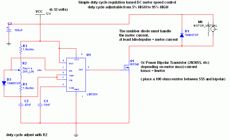
The 555 Ic is wired as an astable and the frequency is constant and independent of the duty cycle, as the total resistance (R charge + R discharge, notice the diode) is constant and equal to 22Kohm (giving a frequency of about 1Khz, notice the hum).

When the potentiometer is all up, the Rcharge resistance is 1,0 Kohm (the diode prevents the capacitor to charge through the second potentiometer section and the other 1,0 Kohm resistor), and Rdischarge is 21 Kohm, giving a 5% on duty cycle and a 1Khz frequency.

When the potentiometer is all down, the Rcharge resistance is 21,0 Kohm (the diode prevents the capacitor to charge through the second potentiometer section and the other 1,0 Kohm resistor), and Rdischarge is 1 Kohm, giving a 95% on duty cycle and a 1Khz frequency.

When the potentiometer is at 50% , the Rcharge resistance is 11,0 Kohm (the diode prevents the capacitor to charge through the second potentiometer section and the other 1,0 Kohm resistor), and Rdischarge is 11 Kohm, giving a 50% on duty cycle and a 1Khz frequency.

The 555 provides a good current capability to drive the MOSFET fast and to drive a bipolar transistor.

I actually use this system to drive the DC motor of my small Rotary spark gap Tesla coil at variable speed

If you are disgusted by the 1Khz hum of the motor try to rise the frequency out of the audible range (replacing the potentiometer), but remember that at higher frequency inductive reactance of motor rises so the efficiency would drop.

Important

Obviously the MOSFET (or bipolar) must have enough current capability to drive the motor, so the drain (or collector) current must be equal to maximum motor current (at power supply voltage, when it is blocked). The snubber diode too, because it shorts the motor on the off cycle. Both MOSFET (or bipolar) and diode have to be hooked (if you don’t want them cooked ;-)) to a heatsink
if the max motor current is more than 100 or 200mA. I suggest to not stress too much the motor with too much work because it overheats both motor, transistor and diode.

If you don’t want braking in the off-cycle just place a resistor in series with the snubber diode, it should raise a bit efficiency but have more inertia when slowing the motor down. The value of the resistor must be R=V(breakdown transistor) / Imax, and the power should be 5W. Mosfets have internal Zener diode, but don’t count on it 😉

On-Off Temperature Control

temp control

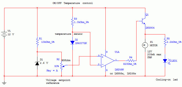
This circuit controls a load (in this case a dc brushless fan) based on a temperature compared with a setpoint. THe transduced is a diode in the forward polarization regime. In fact when forward biased, the forward voltage drop accross a diode has a temperature dependance, in particular has a negative linear(ish) slope. This because of the boltzmann distribuition, causing electrons to pass to the conduction band thermically, lowering the voltage drop accross the diode.

Anyway this circuit comparates a precise voltage reference (zener) with the forward voltage drop of the diode forward biased with 11mA of current.

The comparator is simply a LM158/258/358 working in open-loop mode, the inverting input is connected to the diode sensor, and the noninverting to the reference voltage. Se when the temperature rises above the setpoint, the forward voltage drops under the voltage reference and the comparator output is vccturning on the transistor and so the fan.

Higher power transistor can be substituted for bigger fans, or you can substitute a relay, IGBT, mosfet etc to control higher loads (and higher voltages).

The setpoint is adjusted with the potentiometer, and you can use a LM3914 led driver to make a temperature setpoint indicator (needs careful calibrations and the use of excel to calculate slope and intercept).

Many modifications can be done, but the circuit works very well in its basic form.

THe comparator can distinguish 10uV differences so approx 0.01°C differences (carefully adjusting the potentiometer can allow to feel body heat from 1/2 cm from the sensor, or feel ambient heat, making to turn the fan on and off continuosly)

You can control temperatures up to 140°C (150 max diode temperature), but linearity is not ensured

Possible uses? Heatsink cooling, computer emergency cooling (but i thint that a linear device would be better than a on-off) metal cooling when drilling etc…

Ah! One note: you can even heat with this circuit but you need the reverse comparator inputs and substitute the fan with a relay controlling the heater.

Sound Level Indicator

Sound_Level_Indicator_002

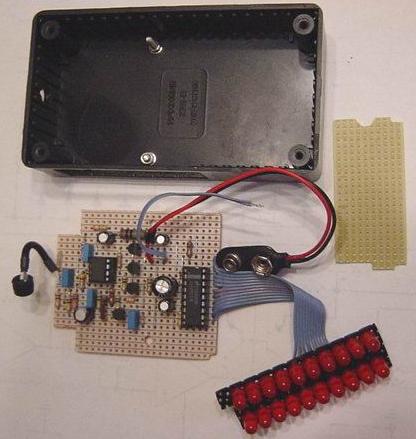
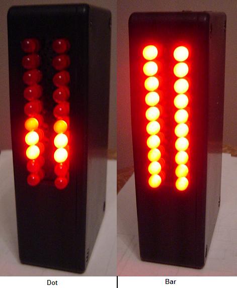
This project uses an LM3915 bar-graph IC driving two sets of ten LEDs for a 30dB range. The circuit is unique because it has an additional range of 20dB provided by an automatic gain control to allow it to be very sensitive to low sound levels but it increases its range 20dB for loud sounds.

The LEDs are operating at 26mA each with the brightness control at maximum, which is very bright. The circuit has a switch to select the modes of operation: a moving dot of light, or a bar with a changing length.

My prototype has a little 9V Ni-Cad rechargeable battery in it to be portable and the battery is trickle-charged when the project is powered by a 9V AC-DC adapter.

Schematic

Sound_Level_Indicator_schematic

Circuit Description

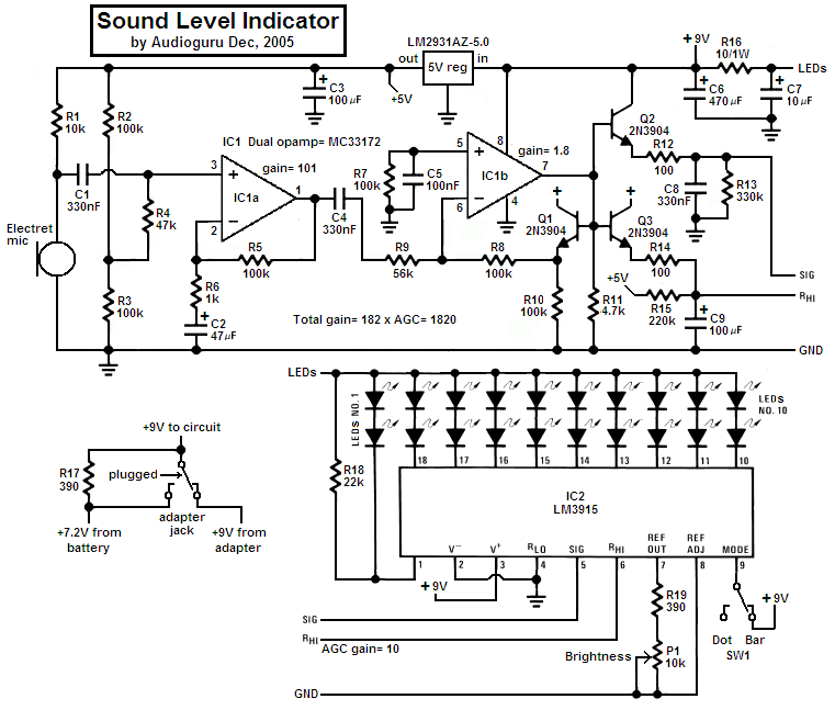
1) The electret microphone is powered by and has a load of R1 from an LM2931 5V low-dropout regulator.

2) The 1st opamp stage is an audio preamp with a gain of 101.

3) The 2nd opamp stage is a single-supply opamp which works fine with its inputs and output at ground and is used as a rectifier driver with a gain of 1.8. It is biased at ground. Since it is inverting, when its input swings negative, its output swings positive.

4) Three 2N3904 transistors are used as emitter-followers:
a) Q1 is inside the negative feedback loop of the 2nd opamp as a voltage reference for the other two transistors. Hopefully the transistors match each other.
b) Q2 emitter-follower transistor quickly charges C8 which discharges slower into R13 and is used as a peak detector.
c) Q3 transistor is the automatic gain control. It is also a peak detector but has slower charge and discharge times. It drives the comparators’ resistor ladder in the LM3915 to determine how sensitive it is. R15 from +5V is in a voltage divider with the ladder’s total resistance of about 25k and provides the top of the ladder with about +0.51V when there is a very low sound level detected. Loud sounds cause Q3 to drive the top of the ladder to 5.1V for reduced sensitivity.

5) The LM3915 regulates the current for the LEDs so they don’t need current-limiting resistors. In the bar mode with all LEDs lit then the LM3915 gets hot so the 10 ohm/1W resistor R16 shares the heat.

Sound_Level_Indicator_004

Options

1) You could use a switch to change the brightness instead of a pot, or leave it bright.
2) You could use an LM358 dual opamp (I tried it) but its output drops above 4Khz. The MC33172 is flat to 20kHz with this high gain.
3) You could add a 1uF to 2.2uF capacitor across R5 so the indicator responds only to bass or “the beat” of music. Then an LM358 dual opamp is fine.

Sound_Level_Indicator_003

Construction

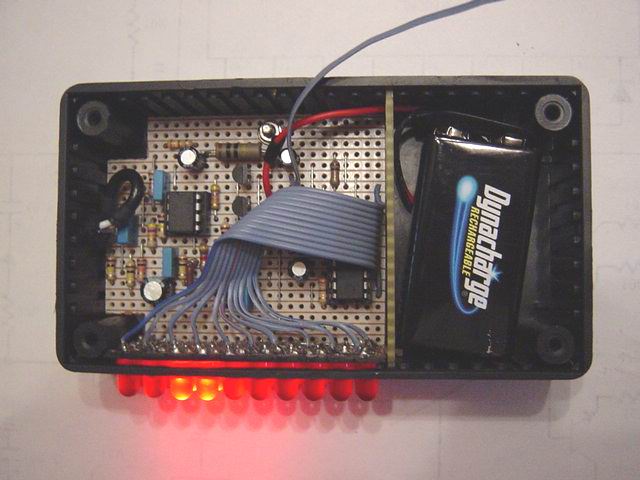
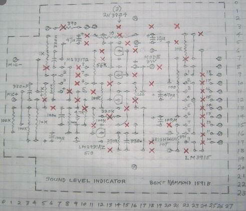
1) The stripboard layout was designed for a Hammond 1591B plastic box with space in the lower end for a rechargeable 9V battery. One bolt holds the circuit board and a second bolt was cut short as a guide.
2) A second piece of stripboard was used on a diagonal to space the LEDs closely together. A few LEDs needed their rim to be filed slightly to fit.
3) A third piece of stripboard was used as a separating wall for the battery and it interlocks with the LEDs stripboard to hold it in place.
4) 11-wire flexible ribbon cable connects to the LEDs.
5) Use shielded audio from the microphone and a rubber grommet holding it.

Sound_Level_Indicator_001

Parts List

R1–10k
R2, R3, R5, R7, R8, R10–100k
R4–47k
R6–1k
R9–56k
R11–4.7k
R12, R14–100
R13–330k
R15–220k
R16–10/1W
R17, R19–390
R18–22k
P1–10k audio-taper (log) pot

C1, C4, C8–330nF
C2–47uF/10V
C3, C9–100uF/10V
C5–100nF
C6–470uF/16V
C7–10uF/16V
IC1–MC33172P
IC2–LM3915P
5V reg–LM2931AZ5.0

LEDs–MV8191 super-red diffused
Electret microphone–two-wire type Box–Hammond 1591B
Battery–9V Ni-Cad or Ni-MH
SW1–SPST switch
Adapter jack–switched

2500W Phase Control

image3

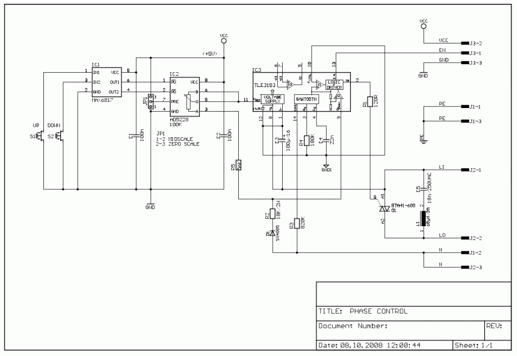
This circuit controls resistive and inductive loads up to 2,500W. Its main functional device is an integrated phase control circuit – Siemens TLE3103. It contains its own power supply, a zero voltage crossing detector circuit and a logic driver. An additional feature is the low voltage input to enable/disable triac firing enabling/disabling the logic driver. The function is as follows: pin13 TLE3103 open (floating), trigger output active, tied to ground trigger output disabled.

Description

An UP and a DOWN pushbutton control a 32-step digital potentiometer (IC2, AD5228) via the debouncer IC1 (MAX6817). The digital potentiometer has a power on reset pin which might be tied to ground causing the potentiometer to start at midscale, or to VCC causing it to start at zero scale. The desired function is selectable using jumper JP1. The triac (capable of driving 40A loads) is a bit overkill for the desired power but the BTA41 has an isolated body and therefore handling of the board under voltage is less dangerous as it is with phase on the package. The snubber circuit uses a 68μH inductance but this might be replaced with a 100 resistor. When replacing the inductance C5 should have a value of 47nF.

Board: Purely single sided, measurements: 3.54X2.15 inches (87.63X54.61mm)

Remark: The debouncer circuit is manufactured with a SOT23-6 package. It might be soldered directly onto the board (DIP-6 package) using thin wires or an adapter board.

image1

Circuit designed by:
Hans-Juergen Zons
102 Moo 9 Lampasak
T. Dong Mon Lek
Mueang, Phetchabun
Phetchabun
67000 Thailand
Email: hjzelec@freenet.de

Parts List

Part Value Package
C1 100n C-5
C2 100n C-5
C3 100/16 ELC3,81
C4 22n C-5
C5 10n/250VAC C-15
D1 1N4005 DO41-10
IC1 MAX6817 AD-SOT23
IC2 AD5228 DIL08
IC3 TLE3103 DIL-14
J1 TE-03 TERMINAL 5.08
J2 TE-03 TERMINAL 5.08
J3 TE-03 TERMINAL 5.08
L1 68H/3A DS30A
Q1 BTA41-600 TOP3
R1 120R R-10
R2 18K/2W R-18
R3 820K R-10
R4 180K R-10
R5 56K R-10
S1 UP BUTTON-02
S2 DOWN BUTTON-02

PCB

You can download all PCBs in PDF format.

BitCake – Electronic Birthday Cake

bitcake_photo1

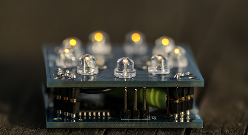
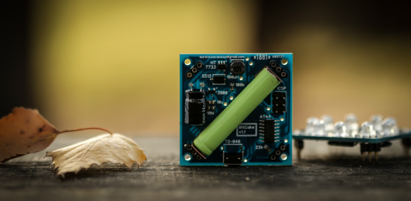
Impress your friend with the ultimate geek’s Birthday Cake! A hand-made open source electronic cake with candles you can blow out!

image_1

Specifications

Features 9 LED candles that you can blow on, to make them flicker and go out, like you do with a real birthday cake! Each candle blinks with random period and phase that depends on the intensity of the air flow

  • Piezo sensor and a special air trap to detect air flow with astounding sensitivity using resonance effect
  • Atmel ATTiny44 microcontroller on board with 4 kilobytes of flash memory and 256 bytes RAM
  • Open source hardware and firmware. Can be re-programmed with an ICSP programmer or Arduino board via Arduino IDE
  • Size 42 x 42 x 18 mm, weight 26g
  • Powered by a single AAAA/LR61 battery (included)
  • 3.3V step-up converter on board
  • Ultra low shutdown current (less than 1 ΅A in deep shutdown)
  • Hand-soldered using lead-free solder

Schematic

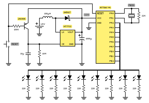
BitCake is an open source hardware product that you can reproduce at home by following this circuit diagram:

bitcake_hardware

The heart of the device is Atmel ATTiny44 microcontroller. Its built-in differential ADC channel with 20x gain is connected to a piezo sensor. The rest nine general input-output pins are connected to nine separate LEDs circuits. A step-up DC-to-DC power converter is used to increase output voltage to 3.3V at the expense of increased current provided by the battery. For that purpose, Holtek 7733 integrated circuit is used. Its SOT-23-5 package has additional Chip Enable (CE) input that turns off the converter into deep shutdown with ultra-low supply current. By pushing the button we open transistor to charge 10 ΅F capacitor that enables the step-up converter. At the same time a reset signal is sent to the microcontroller, so it starts to execute its program. The 10 ΅F capacitor slowly discharges via 10 MOhm resistor so that it will turn off the converter in 3 minutes.

Firmware

BitCake is run by an open source firmware code which you can upload to the device from Arduino IDE. You’ll need either an ISP programmer like USBTiny or another Arduino. Also, you’ll need to install some special ATTiny libraries to the Arduino IDE and select ATTiny44 8MHz board.

Click here to download the code

ToDo

  • Random LEDs flickering when there’s no blowing. The challenge is that LEDs switching (on/off) during piezo sensor sampling phase brings additional noise to blow detection algorithm
  • Charlieplexing algorithm, but this would also require LEDs switching during the sampling phase
  • DIY kit with through-hole components
  • Attachable LEDs of different colors (e.g. using eyelets)
  • A case. There’s a lot of possibilities from polymer clay to 3D printers
  • USB interface and bootloader
  • UV LEDs and UV reactive neon paint

Photos

bitcake_photo2

bitcake_photo3

Halloween Scare using 12F683 and ISD2532

Photo_1

Introduction

Halloween is coming up and it’s time to do some pranks.  

Everyone likes Halloween and I’m no exception. Every year me and my wife decorate the house with lot’s of bugs, spider webs, creepy posters and of course lot’s of Halloween candy.

While making the normal Halloween preparations I came up with the idea of making a circuit that would make some scary noises and also would react to movement.  

I expect to get some screams and laughs from friends that come to visit us this year.  

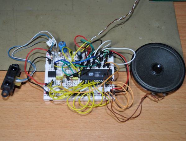
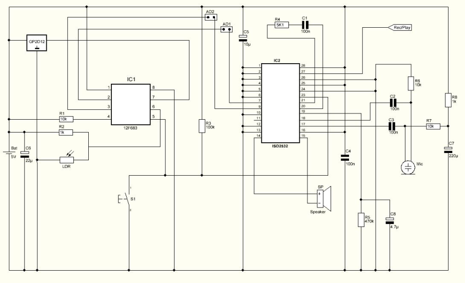
The circuit is basically a sound chip that records and stores sounds in memory and plays them back with a microcontroller and it’s triggered by light and motion.

The sound chip is from maker winbond and has a very good sound quality.

Schematic

Schematic

Parts List

R1                   10K ohms resistor
R2                   1K ohms resistor
R3                   100K ohms resistor
R4                   5K1 ohms resistor
R5                   470K ohms resistor
R6                   10K ohms resistor
R7                   10K ohms resistor
R8                   1K ohms resistor
LDR                Light dependent resistor
C1                   100nF capacitor
C2                   100nF capacitor
C3                   100nF capacitor
C4                   100nF capacitor
C5                   10uF capacitor
C6                   22uF capacitor
C7                   220uF capacitor
C8                   4.7uF capacitor
SENSOR        GP2D12 from Sharp
IC1                  12F683 microcontroller from Microchip
IC2                  ISD 2532 from winbond
S1                    Push button
SP                    Speaker
MIC                Electret microphone
 
Others:
Box
PCB
Jumpers
4.8V Battery Pack
Hex program for the microcontroller

PCB

The PCB, which you can find it below, used for this Project is double layer and its size is 80.66 mm x 47.70 mm.

How it works

This circuit has 2 sensors. One motion sensor ( Sharp GP2D12 ) and a light sensor ( LDR ). The microcontroller monitors both sensors and triggers the sound chip in certain conditions.

Every time the circuit is powered on, the microcontroller stores the distance read by the sharp sensor and uses this as reference for the space available for object/people detection. Anything moving in front of the sensor up to that reference activates the first stored sound.

The other 3 sounds are time triggered only when the light is out. The LDR senses the light intensity and only when placed in darkness it will activate the remaining sounds. Sometimes the sounds are individually played and sometimes combined. There are 4 sounds slots available with max. length of 6 seconds each.

How to record sounds

The PCB has some connectors with jumpers making it possible to change from record to playback mode and vice versa.

Connector #1 named REC/PLAY is a 3 pin connector and jumper connection must be placed to the left side for record mode or to the right side for playback mode.

Also connector #2 named Jumpers must have 2 jumpers installed for playback mode. This is responsible for the memory address of the sounds.

When in record mode, some wire jumper connections must be made to change the address of the recordings manually connecting pin 2 and 3 to VDD or VSS according to table bellow:

table

For VDD and VSS connections it’s possible to use connector named + –

Recording: With power off, connect a microphone, move jumper to record mode and connect message pin 2 and pin 3 to VSS.

  • Turn on the power and prepare the sound you wish to record for #1 sound.
  • Press and keep the S1 push button while recording. Release the button to stop recording.
  • Connect pin 2 to VDD and keep pin 3 to VSS – this will address sound #2.
  • Press and keep the S1 push button while recording. Release the button to stop recording.
  • Connect pin 2 to VSS and pin 3 to VDD – this will address sound #3.
  • Press and keep the S1 push button while recording. Release the button to stop recording.
  • Connect pin 2 to VDD and keep pin 3 to VDD – this will address sound #4.
  • Press and keep the S1 push button while recording. Release the button to stop recording.
  • Turn the power off, disconnect microphone, restore address jumpers and move jumper to playback mode.

Hex Program

The Hex program named HSCARE.HEX, which can be found below must be saved in the 12F683 microcontroller’s memory before soldering on the PCB.

Assembly and testing

After soldering all components on the PCB and once all sounds are recorded it’s time to get it inside a box. I’ve found the perfect box for this project… this skull.

Photo_2

Photo_3

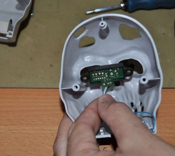
Placing the motion sensor in the eye section.

Photo_4

The sharp sensor adds a crazy eyes look to this skull.

Photo_5

The skull is ready to make some noise and scare the visitors.

Conclusion

This is a very cool Halloween project. It’s possible to record personalized sounds making this even more interesting. I bet that this project will bring many screams and laughs.


Hand Steadiness Tester

Photo_1 (1)

Introduction

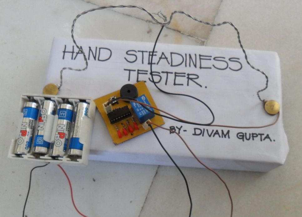
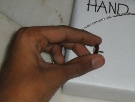
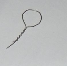
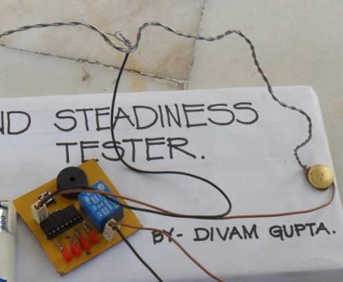
The Hand Steadiness Tester is a game which tests the steadiness of your hand. The player has to take the ring from one end to another end without touching it to the wire. In this the player gets 4 turns. If the player touches the wire 4 times he has to reset the game & start the whole game from the beginning.

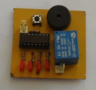
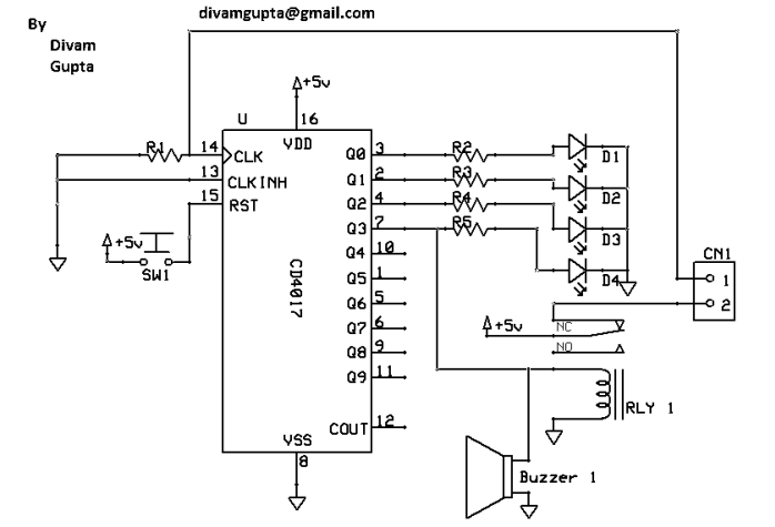
This project consists of IC 4017, a Buzzer, a Relay, some resistors, a Push button and 4 LEDs. There is also a PCB layout given. There are many types of Hand Steadiness Testers which are very simple. This New Hand Steadiness Tester is more advanced.

When the player touches the wire one time 1st LED turns on. When he touches 2nd time the 2nd LED turns on. When he touches 3rd time the 3rd LED turns on. When he touches 4th time the 4th LED turns on & the buzzer starts beeping. To stop the buzzer he has to push the reset button.

Photo_2

Schematic

Schematic

Parts List

1.       R1                   10K

2.       R2 – R5            330 ohms         

3.       D1 – D4           3v LEDs

4.       IC1                 IC 4017        

5.       SW1               Push Button     

6.       Buzzer 1          5v Buzzer    

7.       RLY 1              5v Relay           

8.       CN1                2 Pin Connector 

PCB

The circuit board is a Single Sided PCB with no SMT components (Very easy to make & solder). This is made in Express PCB. The PCB files are down below.

Explanation

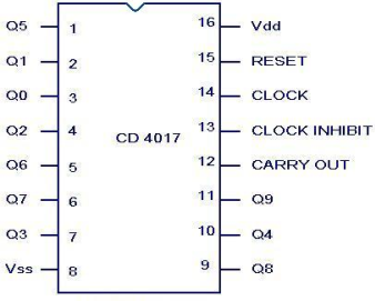
Pinout

This is IC 4017. Q0 -Q3 are connected to LEDs through 330ohms resistors. Q3 is also connected to a buzzer & a relay. When we touch the wire with the ring, a positive current flows to pin 14.  When the player touches the wire 4 times, the relay gets on; this breaks the contact between the ring and pin 14 of IC. So after that the buzzer keeps beeping. When we push the reset button, the IC resets and the buzzer, the LED & the relay gets off.

How to make it

Photo_3

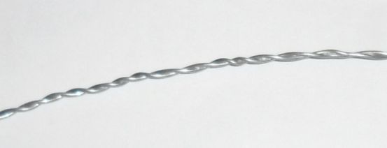
Then you need a wire. You should use a thick wire. Or you can take 2 wires and twist them to make it thick.

Photo_4

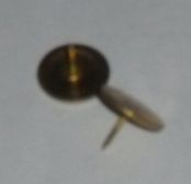
Then you need 2 thumb pins to attach the wire with the base.

Photo_5

Now attach the both the ends of the wire to the board with the thumb pins.

Photo_6

Photo_7

Now you have to shape the wire in the way you want.

Photo_8

Photo_10

Photo_9

Photo_11

After that you need to make a ring. You can make it by a wire or you can use a key ring.

Photo_12

Photo_13

Now you need to attach the circuit. Take a connector and attach one wire to the ring and the other wire to the thumb pin.

Photo_14

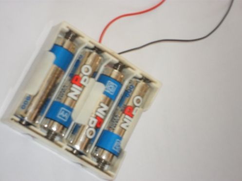
Now you just have to attach the battery. You can use a power supply circuit to give it exact 5 volts. You can also use 4 1.2 volts rechargeable cells.

Photo_15

Congratulations!! Your Advanced Hand Steadiness tester is ready.

If it doesn’t work

  • Make sure that your connections are connected well.
  • Make sure that your PCB is fabricated well.
  • Make sure that batteries are working

Bomb Game

Introduction

“Should I cut the blue wire… or the red…?” This is a very common phrase in many movies when the action hero has a bomb in front of him with little time left and he has to choose which wire to cut and stop the bomb from exploding saving millions of people.

This game is just that… a count down timer and 4 wires of different colors. The player has to remove each wire until it deactivates the bomb.

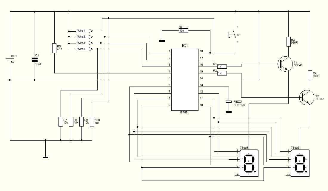
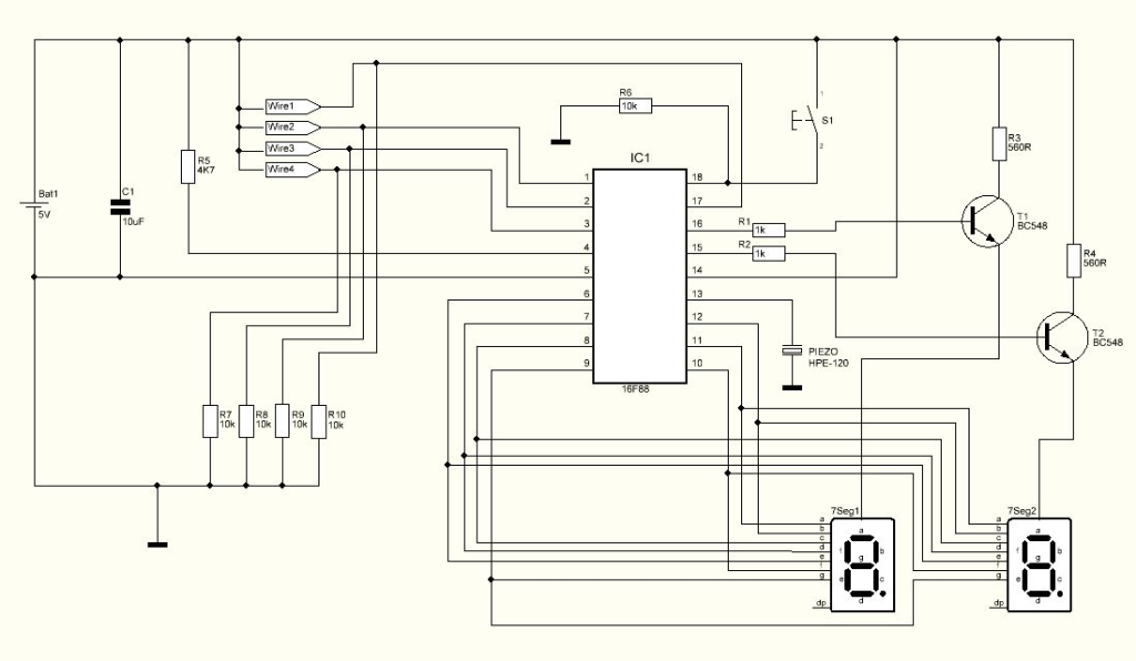
Schematic

Schematic


Parts List

R1                   1K ohms resistor
R2                   1K ohms resistor
R3                   560 ohms resistor
R4                   560 ohms resistor
R5                   4K7 ohms resistor
R6                   10K ohms resistor
R7                   10K ohms resistor
R8                   10K ohms resistor
R9                   10K ohms resistor
R10                 10K ohms resistor
C1                   10uF capacitor
T1                    BC548 Transistor
T2                    BC548 Transistor
Piezo               HPE-120 piezo
Digits              Dual 7 segment display – LTD6410G
IC1                  16F88 microcontroller from Microchip
S1                    Push button

Others:
Box
PCB
Wires
4.8V Battery Pack
Hex program for the microcontroller

PCB

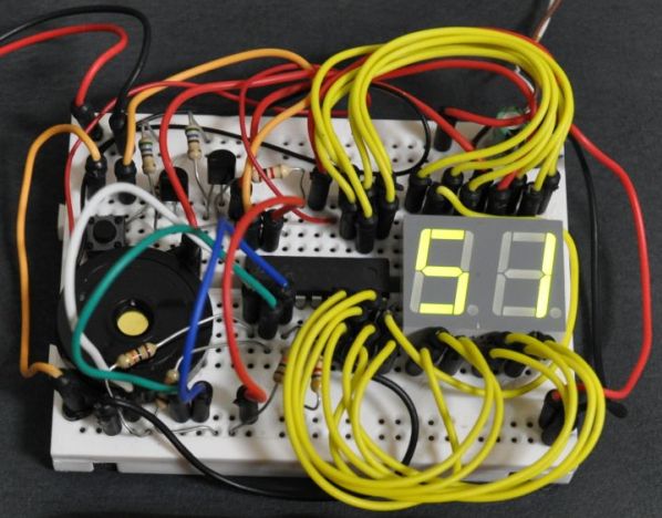
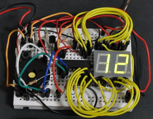
I’ve decided to build my version on a breadboard because it has a more realistic look. All the wires and components create a better game experience. Anyway I have made a pcb drawing making it possible to create a clean build. The PCB used for this Project is double layer and its size is 70.79 mm x 42.01 mm. Download the PCB files on the bottom.

How it works

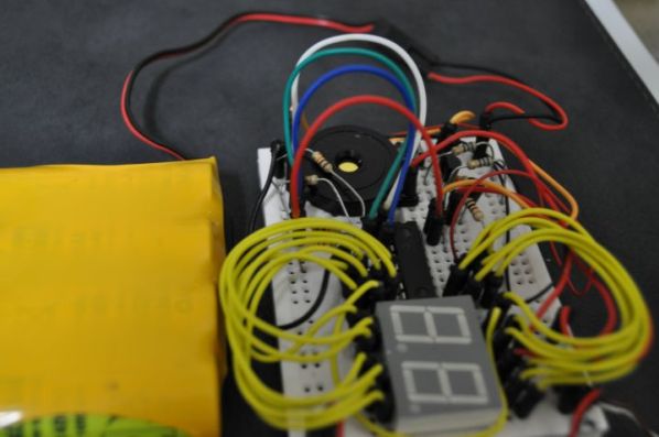
Turning the power on, the display and piezo will start small introduction.
After the introduction, the message “S1” will appear on the display meaning that S1 needs to be pressed for the game to start.
All four wires must be plugged in. If one of the wires is not plugged in, the message “EE” will display meaning that an error occurred and the game will not begin.

As the game begins, the count down will start. The display shows the timer and 15 seconds is all the time we have to defuse the bomb.

There are four wires – red, green, blue and white. Unplugging them will simulate the cutting of the wire. Only one wire can be unplugged at a time and each wire can only be used once per play.

There are four actions possible – defuse the bomb, explode the bomb, increase timer speed and no consequence.

There is no need to change the color position because each position will correspond to a random action.

Every time a wire is unplugged, its action will be randomly given meaning that it’s possible that even all of the wires will not defuse the bomb.

photo_2

Main menu – waiting for S1 to be pressed to start the game

photo_3

Counting down – time to choose which wire to pull

photo_4

Four wires – red, blue, green and white

Hex Program

The Hex program named Bgame.Hex must be saved in the 16F88 microcontroller’s memory before soldering on the PCB. Download HEX in the files at the bottom.

Testing

A video of this project working can be found at the link: http://www.youtube.com/watch?v=YnFUfPpllh8

Conclusion

It’s an original game and can bring a lot of fun to the kids.

For a final look it’s possible to cut 3 pieces of PVC tube, paint them in red and glue the circuit on the tubes. This will make the traditional look of the dynamite bomb.

Motion Activated Led Dice

photo_4

Introduction

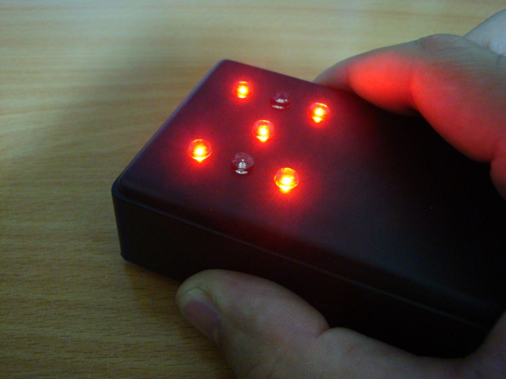
I’ve always wanted to build an electronic led dice, but something different from what we see on the internet. Making it motion controlled… now that’s new!   Many new cell phones that have accelerometers built in also have dice games. These dice move when shaking the cell phone. My Led Dice project will also work with a shake motion but without the use of the expensive accelerometers.

schematic

Parts List

R1                   500 ohms resistor
R2                   500 ohms resistor
R3                   500 ohms resistor
R4                   500 ohms resistor
R5                   500 ohms resistor
R6                   500 ohms resistor
R7                   500 ohms resistor
R8                   10K resistor
C1                   100nF cap
Led1 to 7        5mm flat led
Piezo               Piezo HPE-120
IC1                  16F688 microcontroller from Microchip
S1                    Normal On/Off switch
 
Others:
Box
AAA x2 battery support
PCB
Spring, screws and wire
Hex program for the microcontroller

PCB

The PCB used for this Project is single layer and its size is 31.27 mm x 42.25mm.

I’ve used x2 AAA batteries to supply 3V to this circuit making it small and light.

Download PCB files at the bottom.

The Trigger

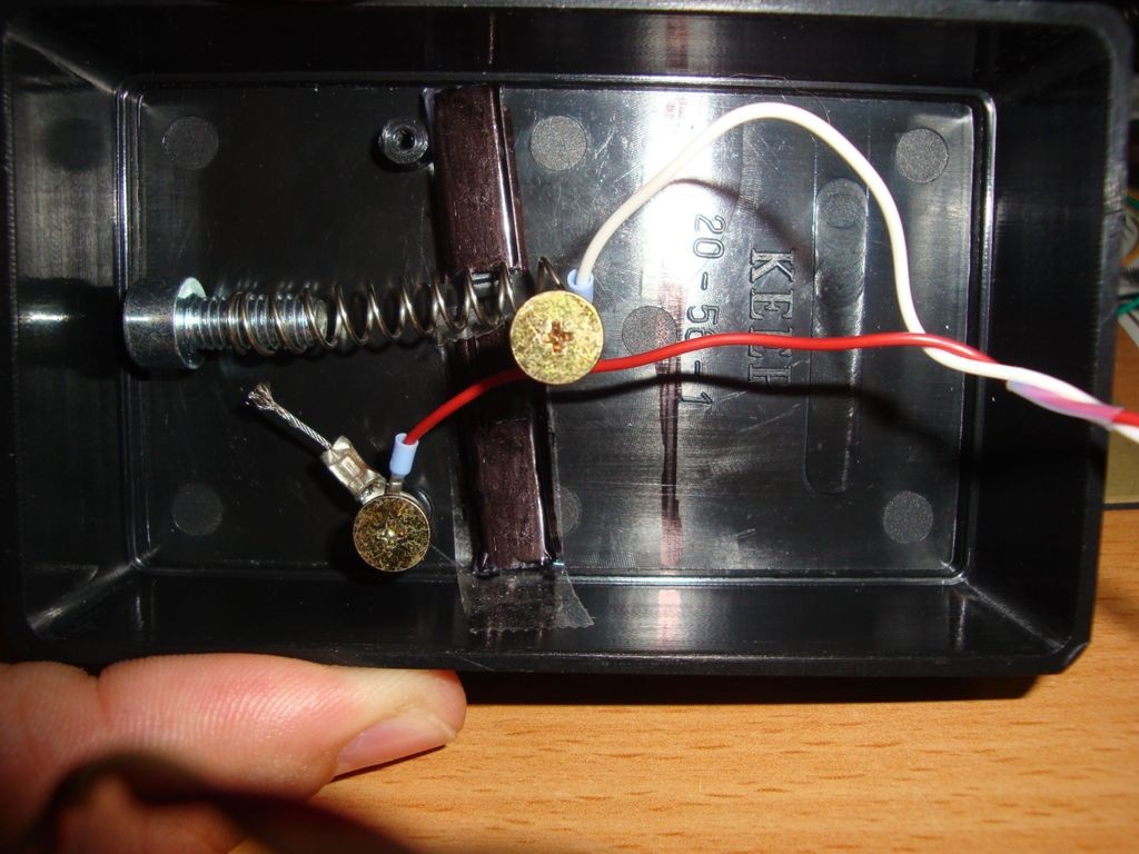
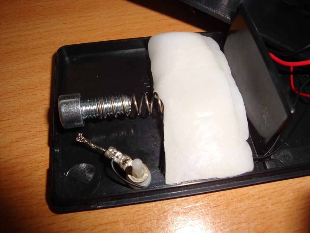
The trigger is a mechanical device and it will sense the shaking movement. One contact will be on a spring and the other contact will be on a wire. The spring has a screw on it’s end and it will act as a weight. Placing the box on it’s side, the spring needs to have enough strength not to bend with it’s own weight. Shaking will make the spring to move and touch the wire closing the circuit and this way the microcontroller will know when it’s time to roll the dice.

photo_1

Adding a small amount of polymorph will secure the spring and give a better final look.

photo_2

Hex Programm

The Hex program must be saved in the microcontroller’s memory before soldering on the PCB.
The fuses OSC and MCLR fuses must be set as follow:
 
INTOSCIO                 on
MCLR                         off

Testing

Turning on the circuit, the microcontroller will initialize and light on and off all leds.
 
Shaking the box will roll the dice. The leds will simulate the rolling of the dice and the piezo will sound until the final number is displayed.
 
Once the final number is displayed it’s possible to sort another number simply by shaking the box again.

Conclusion

It’s a pretty cheap and easy to make circuit.
 
Will add more fun to any board game.

LED effects

IMG_3729


Introduction

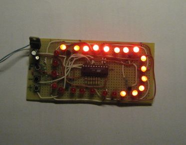
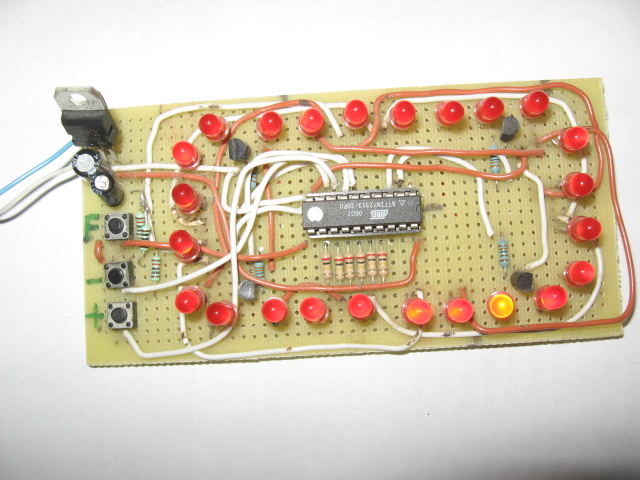
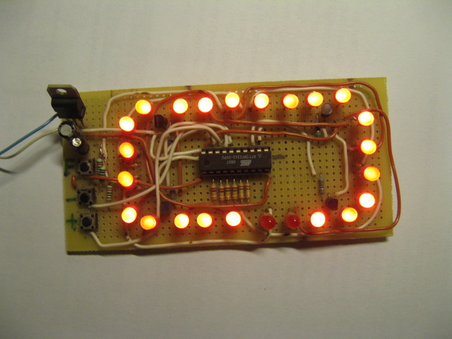
This project I made for my little daughter. It is 24 channel light illumination. The schematic is very simple – 24 LED’s, 1 MCU and some additional components. The main principle is dynamic indication, which is usually implemented for control of 7-segment digital indicators. Here is the same, as for indicators are used traditional 5-mm LED’s.

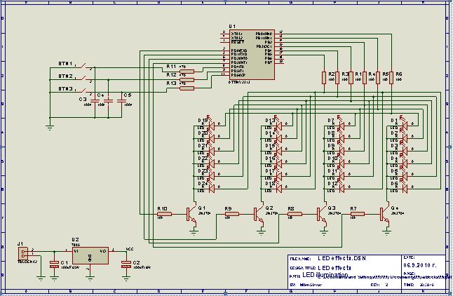
For control unit is implemented not expensive MCU ATTYNI2313 (Atmel), which can drive direct LED (up to 20 mA on each pin). As you can see on the schematic, 24 LED’s are grouped in 4 groups, each one consist 6 LED’s. LED’s in group 1 indicate the content of register r0 of MCU, LED’s in group 2 – r1, LED’s in group 3 – r3 and LED’s in group 4 indicate the content of register r3. Dynamic indication do this, as in each moment of time indicates content of one register and scans them consecutive. For instance, when the content of r1 is loaded in output port (PORTB), the transistor Q2 is switched “ON”, and the LED of group 2 indicate the bits in r1.

IMG_3736

There are 3 buttons – “F”, “+” and “-“. The button F is for change of effect, and buttons “+” and “–” are for increasing or decreasing the speed of effect. For example, each time when you press button “-” changing of lights go more slowly. For fast changing of speed you can press and hold the appropriate button.

The speed of effects is independent of speed of dynamic indication, which is constant.

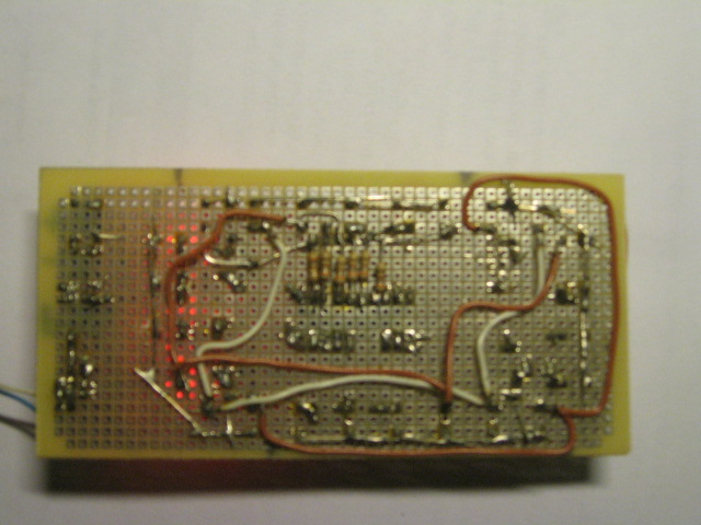
The schematic can be powered by any DC adapter for 8 to 15 V / 100mA. I use 12V adapter and for the stabilizer 7805 there is no need of heat sink for them – this is one of advantages of implementation of dynamic indication. Others advantages are simple schematic and PCB, lower pin count of MCU etc.

IMG_3732

Software is written in assembler of IDE AVRStudio 4. The program code is below. There are a lot of comments for explanation how the program works. With simple changes in code everyone can make different effects and/or add them. Each effect can be up to 24 stages.

If the LED pins are made longer with additional wires, LED effects can be used for Christmas tree or for advertising text on shop window (for instance). If there is need, LED number can be easy increased up to 32 LED’s and stages. Enjoy!

IMG_3738

Schematic

schematic_th

TOP PCB Companies