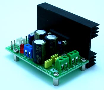

This project is a 5.5W – 2 Channel Audio Amplifier based on LA4445 IC.
Description
The small 2 Channel amplifier constructed around Sanyos LA4445 IC delivers 5.5Watts +5.5 Watts at 4 ohm load, supply in 12V DC 2Amp, Input impedance 30K.
Specifications
- Dual Channels output : 5.5W
- Minimum External Parts
- Very small pop noise at the time of power supply ON/OFF
- Good ripple rejections
- Small residual noise
- Built-in protectors 1. Thermal Protector 2. Overvoltage Surge Protector
- Standard Audio signal
- Supply 12V DC
- Load : 4 Ohms Speaker on Each Channel
- Voltage Gain : 50DB
- Output 5.5W on each Channel (THD 10%)
- Total harmonic distortion 1% Max @ Po=1W
- Input impedance 30 K-ohms
Schematic

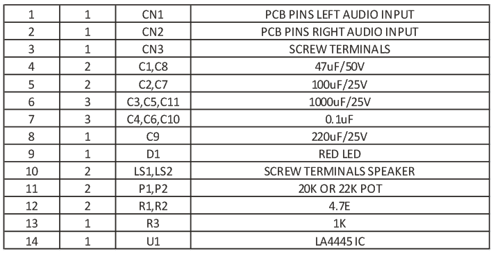
Parts List
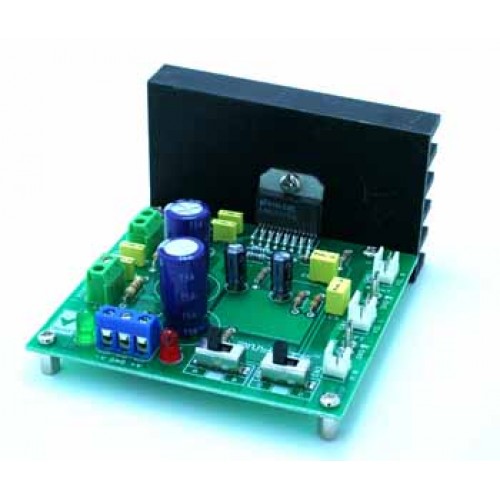

This project is a 14W Stereo Audio Amplifier based on LM4730 IC.
Description
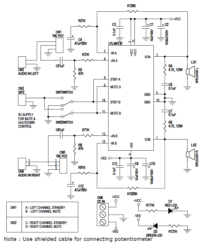
14W Stereo audio power amplifier build around LM4730 IC. The LM4730 is stereo audio amplifier capable of delivering typical 14W per channel of continues average output power a 4 Ohms or 8 Ohms load with less than 10% THD+N from 20Hz to 20Khz frequency. Each amplifier has an independent smooth transition fade-in/out mute and a power conserving standby mode which can be controlled by onboard slide switches.
The LM4730 has short circuit protection and thermal shutdown feature that is activated when the IC temperature exceeds 150 centigrade. The LM4730 also has under voltage lock out feature for click and pop free power off and on. Amplifier required proper heat sink.
Applications
- Audio Amplifier for High End Stereo TVs
- Audio Amplifier for Component Stereo
- Audio Amplifier for Compact Stereo
- Audio Amplifier for PC
- Audio Amplifier for Self Powered Speakers
Specifications
- Outout Power into 4 Ohms or 8 Ohms , 14W
- THD+N 10%
- THD+N at 1Khz with 2X1W into 8Ohms 0.02%
- Mute Attenuation 85dB
- Standby Current 3.5mA (+/- 17V)
- Dual power supply – ±18 VDC
- Less then 10% THD+N from 20 Hz – 20 KHz
- Onboard slide switch for mute and standby mode
- Terminal pins for connecting left and right audio signal inputs
- Header connector for connecting Potentiometer (POT) for volume adjustment
- Power Battery Terminal (PBT) for easy dual power supply and speakers connection
- Power-On LED indicator
Schematic
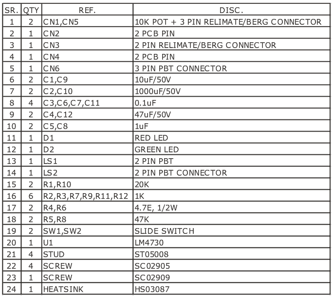
Parts List

This project is a mini Audio Amplifier based on LM386 IC.
Description
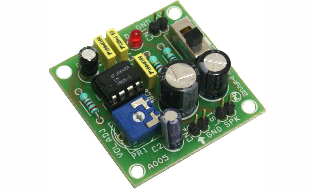
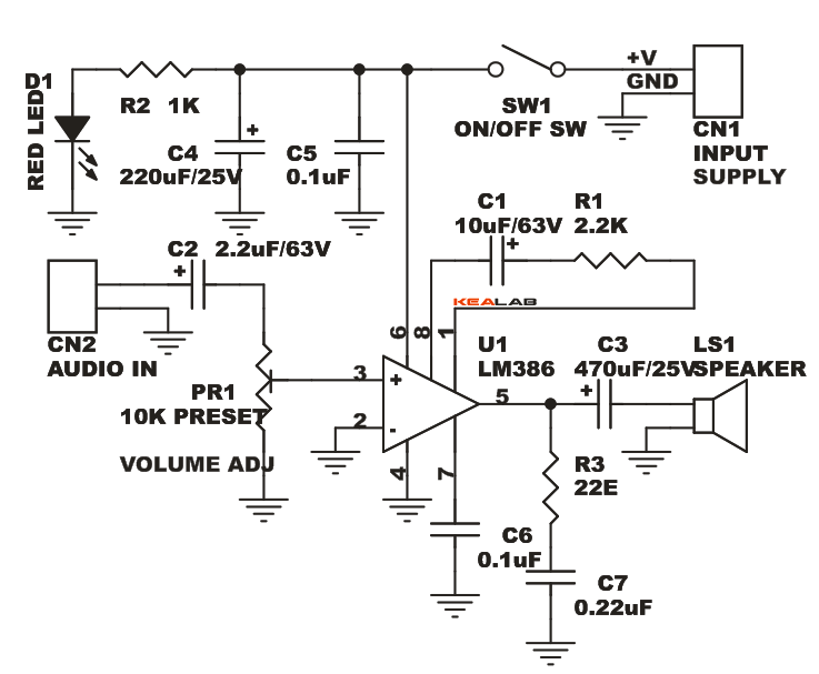
The Mini Audio Amplifier project is a good choice for battery operated gadgets. It is based on Texas instruments LM386 IC, provides high quality Audio.
Specifications
- Wide power supply input 6 to 12 VDC
- 500 mW output @ 8 Ohms load
- Takes standard audio signal as input
- Low quiescent current drain 4 mA IC
- The quiescent power drain is only 24 mW when operating from 6 VDC
- Onboard preset for volume adjust
- Header connector for connecting power supply, audio signal and speaker
- Onboard power indication LED
- On/Off PCB mounted slide switch for power supply
- Four mounting holes of 3.2 mm each
- PCB dimensions 41 mm x 41 mm
Schematic

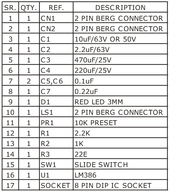
Parts List
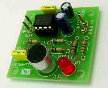

This project is a microphone pre-amplifier based on LM358.
Description
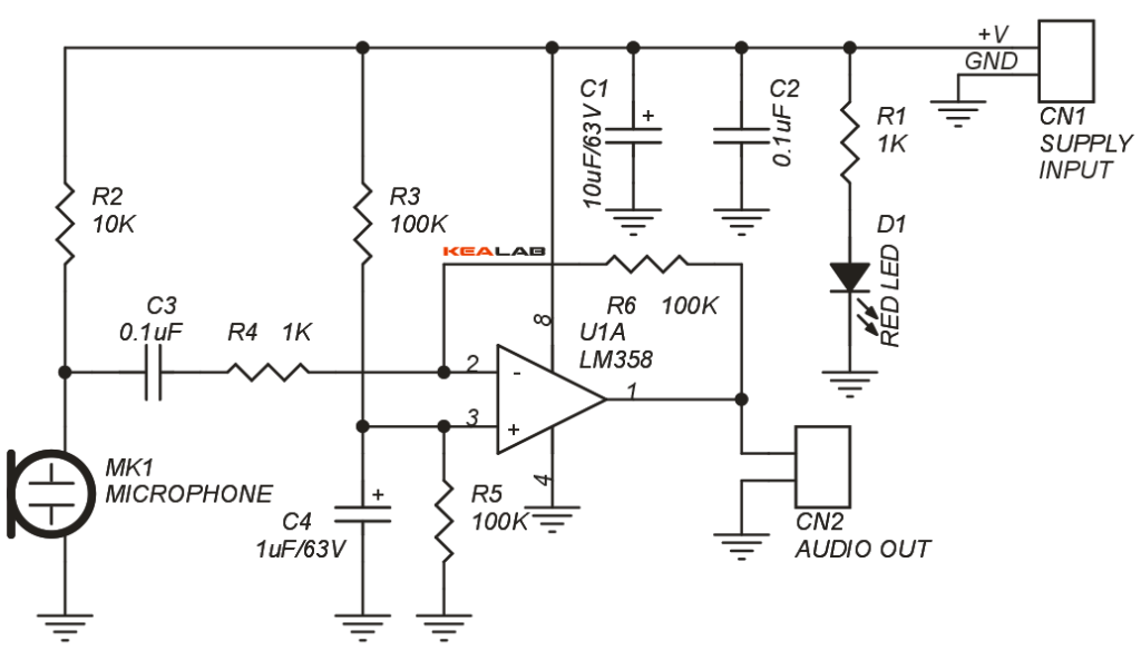
This is an easy to construct microphone pre-amplifier project using a compact electret condenser microphone. The pre-amplifier is the important building block of many audio communication systems. The circuit has been built around Op-Amp LM358.
- Power supply : 5 to 12 VDC @ 10 mA
- Output: Gain Approx. 100
- On-Board electret condenser microphone
- Header connector for connecting of power supply input and audio output
- Power-On LED indicator
- Four mounting holes of 3.2 mm each
- PCB dimensions 35 mm x 40 mm
Schematic
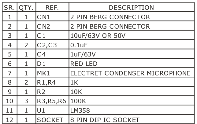
Parts List
Gerber View

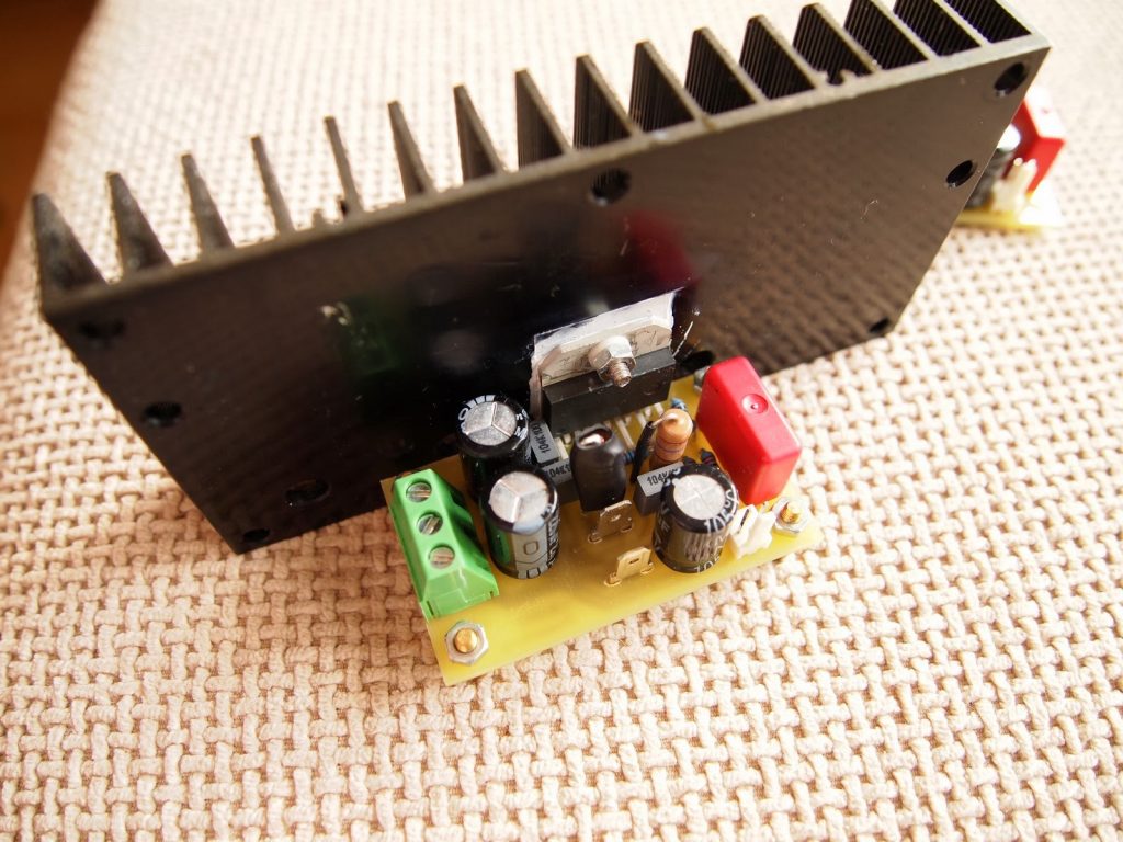
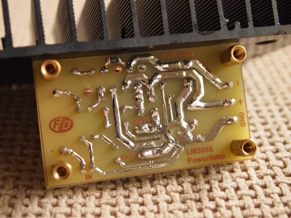
This project is an audio amplifier based on LM3886.
Description
This is my second encounter with LM3886. I was pleased of the sound this chip produced the first time, so I decided to make another amplifier with it. The schematic is based on the schematic in the datasheet of the chip with minor changes.
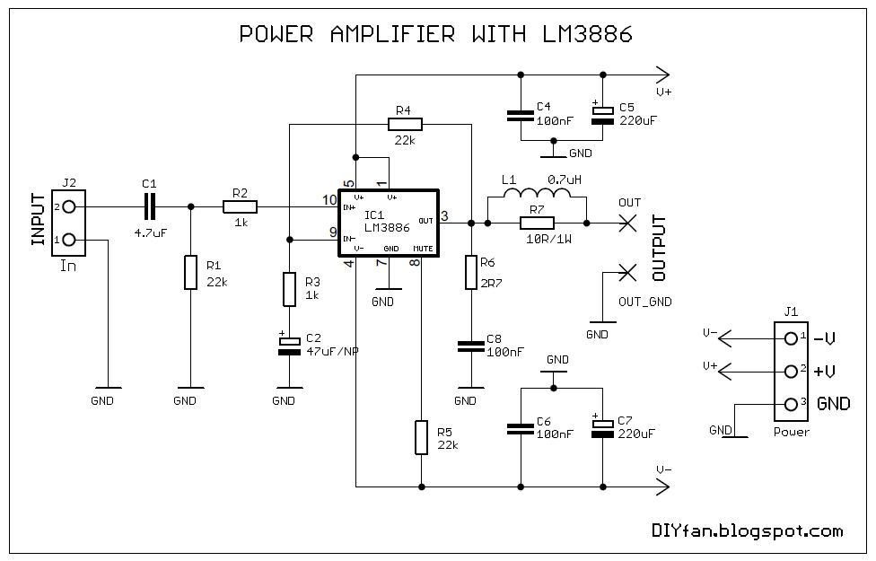
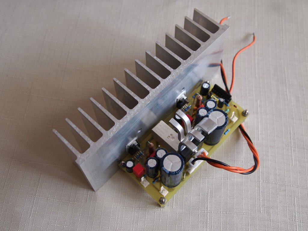
I removed the time delay capacitor connected to MUTE pin, because it’s better to use separate DC protection schematic which has similar functionality. I made the output inductance L1 by winding 15 turns of enameled wire around the resistor R7. The diameter of the wire must be minimum 0.4mm. The whole was wrapped with heat shrink. I used 47uF/63V non polarized capacitor for C2. It can be regular electrolytic capacitor, but it’s better to use non-polarized or bipolar.
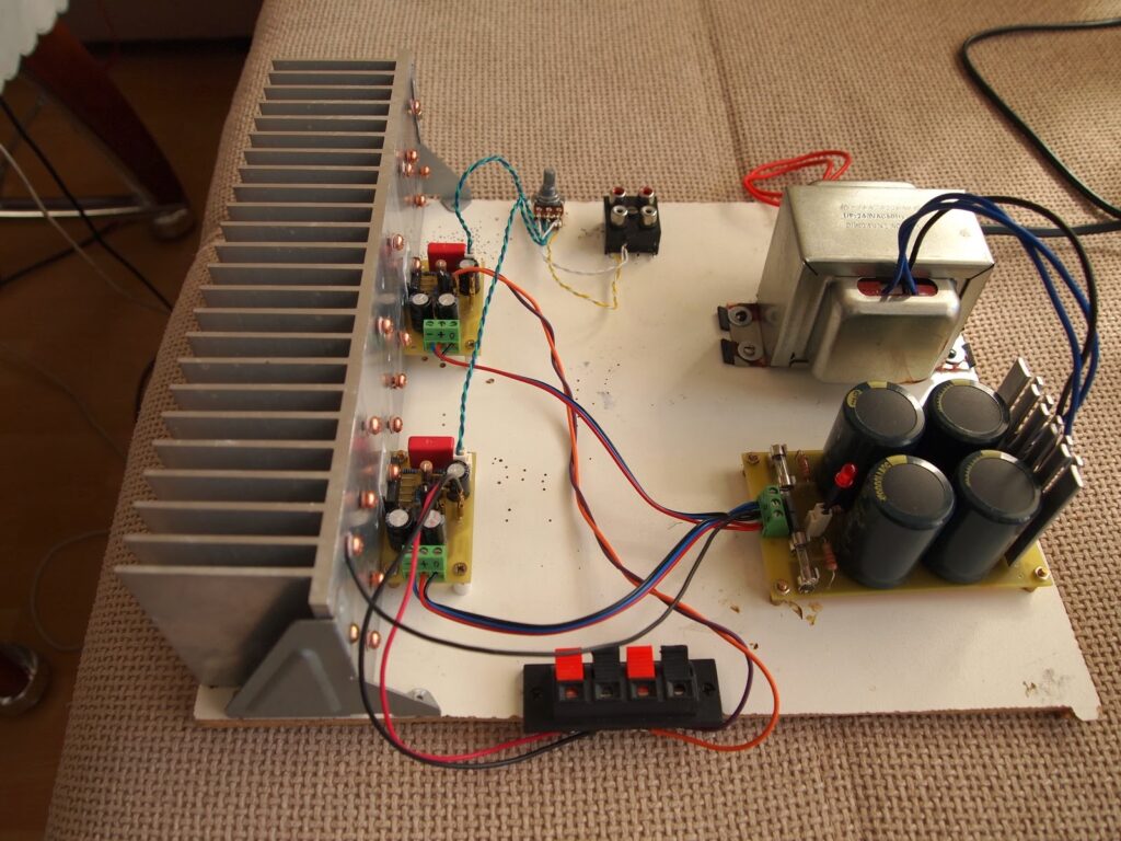
The transformer is 2x24VAC / 105W. The test was ran with 8Ohm dummy load and the big heat sink gets only warm after hours of playing music from my computer at max volume. The transformer is a little weak for this amplifier, maybe 150W or 200W would be a better choice.
The power supply is very simple – a bridge rectifier and 4 x 10 000uF/50V capacitors. If the input is disconnected and open there is a little hum which can be heard only with an ear pressed against the speaker. But once the amplifier is connected via cable to the source and there is no signal, it becomes absolutely silent. Also if the heat sink is isolated from the metal tabs of the chips with some mica pads then the heat sink is good to be connected to the ground as it induces more hum in the open inputs.
It can be mounted without isolation pads for better thermal conductance, but then the heat sink itself must be isolated from the metal enclosure which usually is connected to the ground. How does it sound? Excellent 🙂
Schematic
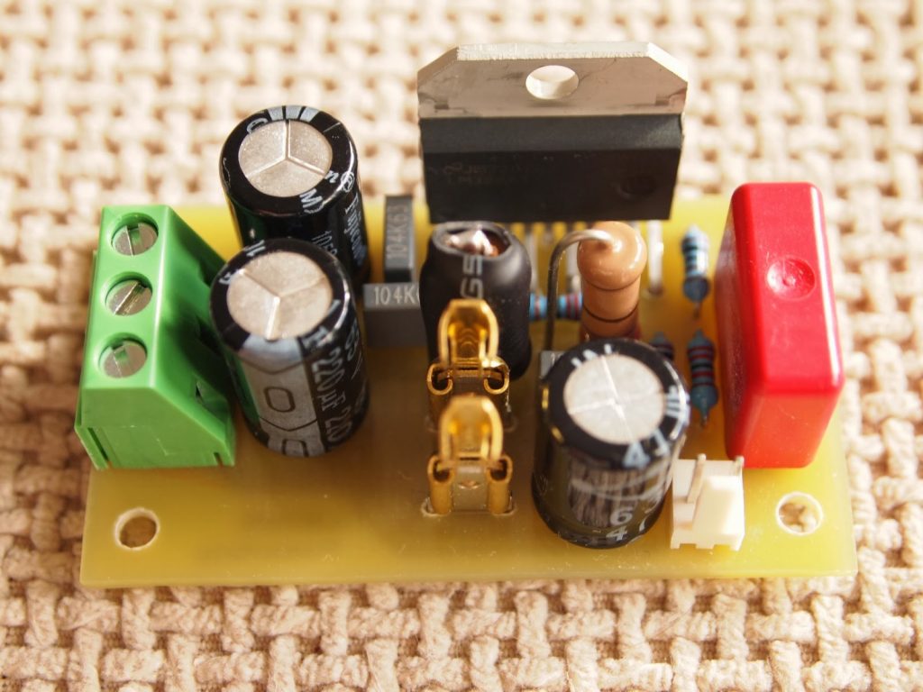
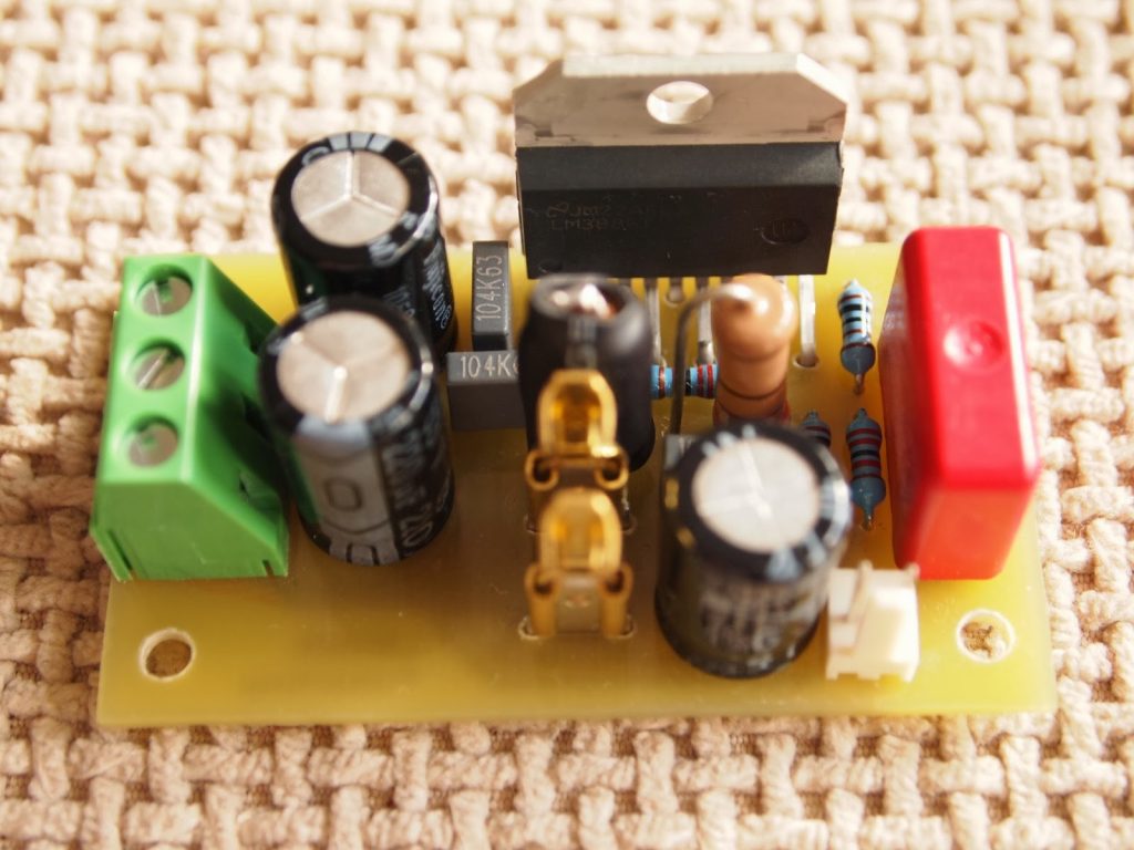
Photos

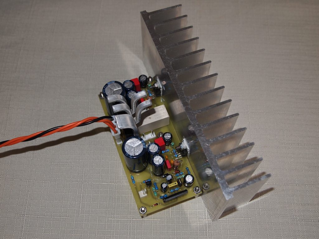
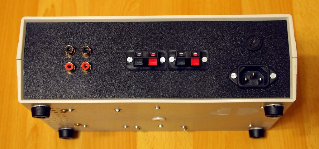
This project is an audio amplifier based on TDA2050 and LM1875.
Description
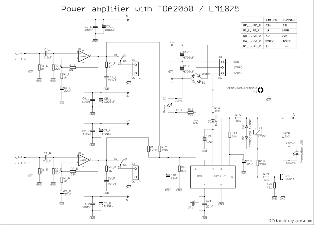
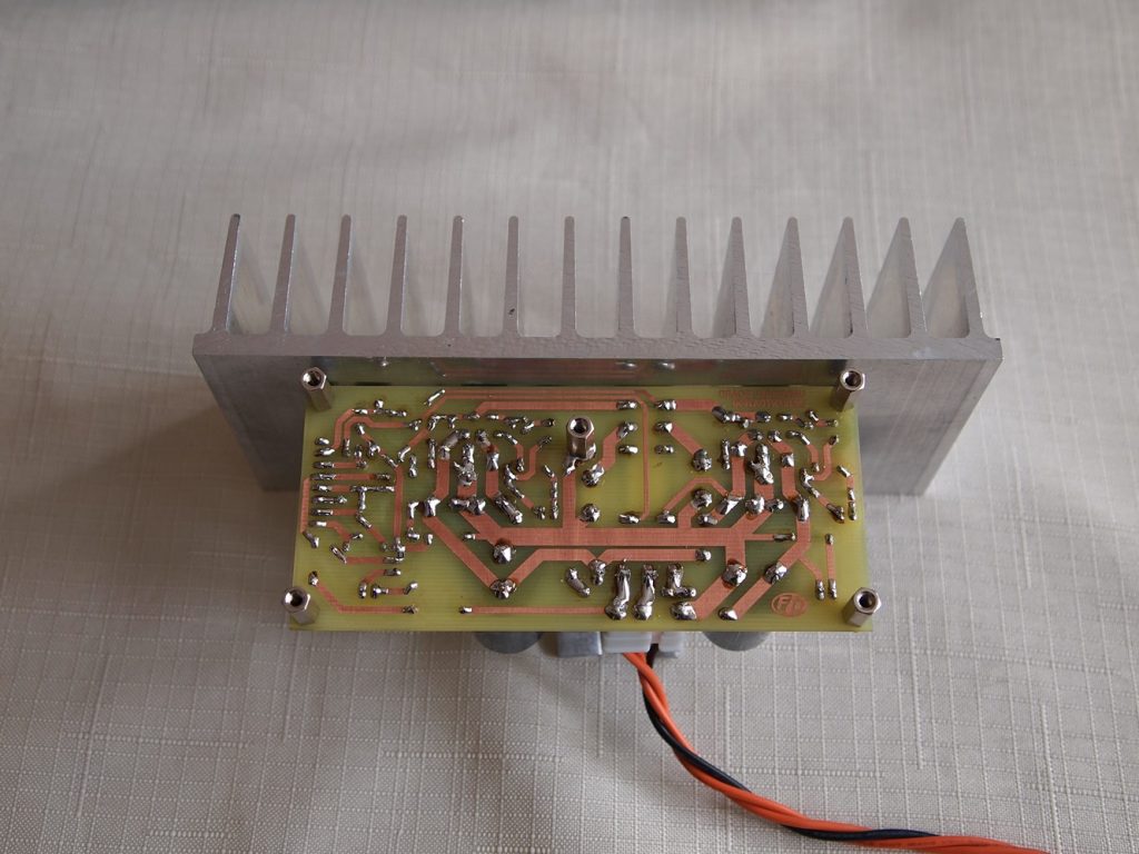
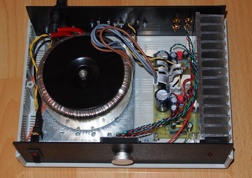
This is not an ordinary project, but an attempt to make a PCB that is suitable for TDA2050 andLM1875 and has all the necessary circuitry on board – power supply, speaker protection, delayed turn-on and fast turn-off. This is achieved using the convenient uPC1237 IC.
TDA2050 and LM1875 are pin to pin compatible, the differences in their schematics are the values of a couple resistors and one capacitor. All this allows to make an universal circuit board, suitable for any of these two ICs.
It is 2x30W, but it depend of the power supply voltage and the impedance of the speakers connected to the output.
Schematic
Parts List
B1 KBU8M FBU4
C1 100nF C050-024X044
C2 100nF C050-024X044
C3 1000uF E5-10,5
C4 1000uF E5-10,5
C6 2.2uF C050-075X075
C7 220nF C050-030X075
C8 22uF E3,5-8
C9 100nF C050-024X044
C10 100nF C050-024X044
C11 1000uF E5-10,5
C12 1000uF E5-10,5
C13 4.7uF E2,5-6
C14 2.2uF C050-075X075
C15 220nF C050-030X075
C16 22uF E3,5-8
C17 4700uF E7,5-18
C18 4700uF E7,5-18
C19 47uF E2,5-7
C20 22uF E3,5-8
C21 22nF C050-025X075
D5 1N4148 DO35-7
D6 1N4004 DO41-10
D7 BZX85C12V DO41Z10
H1 MOUNT-PAD-ROUND3.0 3,0-PAD
IC1 LM1875 T05D
IC2 LM1875 T05D
IC3 UPC1237 SOP8
IN 6410-02
IN1 6410-02
J1 OUT1 AC2
J2 OUT2 AC2
J3 AC AC3
JP1 JP1
K1 G2R2 G2R2
LED 6410-02
LED2 LED5MM
LED3 6410-02
R1 1k 0207/2V
R2 20k 0207/12
R3 22k 0207/7
R4 1M 0207/7
R5 1R 0414V
R6 1k 0207/2V
R7 20k 0207/12
R8 22k 0207/7
R9 1M 0207/7
R10 1R 0414V
R11 2k2 0207/7
R12 120k 0207/7
R13 120k 0207/10
R14 56k 0207/7
R15 9k1 0207/7
R16 10k 0207/7
R17 92k 0207/10
R18 330R 0207/10
R19 68k 0207/7
R20 3k9 0207/10
R21 10k 0207/7
T2 MPSA42 TO92-EBC
Photos

This project is a 3 tone siren based on UM3561 IC.
Description
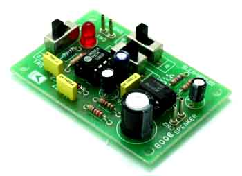
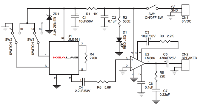
3 Tone Siren project produces Gun Sound, Police Siren and Ambulance Siren effects from a speaker. This project is built around UM3561 IC driving an LM386 audio amplifier to give that extra punch.
Specifications:
- Supply input 6 VDC @ 200 mA
- Output : Speaker, 8 Ω / 0.5 W
- Two slide switches select and play different tones
- On/Off Side switch for supply input
- Terminal pins for supply input and speaker output
- Power-On LED indicator
- Four mounting holes of 3.2 mm each
- PCB dimensions 42 mm x 64 mm
Schematic
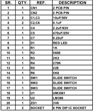
Parts List

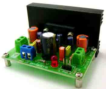
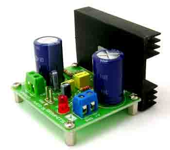
This project is a 5W Stereo Audio amplifier based on BA5406.
Description
5W Stereo Audio Amplifier project based on BA5406 IC which is suitable for application like stereo radio cassette player, stereo components systems etc.
The Heart of the project, BA5406 is a dual OTL monolithic power IC with two built-in, high output speaker amplifier circuits. High output of 5W×2 can be produced when VCC=12 V and RL=3Ω, and 2.8 W×2 when VCC=9V and RL=3Ω. The BA5406, which uses a high allowable power dissipation package, has a simple heat-sink design.
Specifications:
- Good low voltage characteristics (Operation from Vcc=5 V)
- Ripple filter (6pin) also can be used as muting pin (Make 6pin GND potential)
- Small thermal resistance package and simple heat-sink design
- Power supply 5 to 12 VDC
- Output – 5 W + 5W, 3 Ω
- Input resistance – 100 KΩ
- Good distortion (THD – 0.3%), Good channel balance
- Berg pins for connecting of inputs
- Power Battery Terminal (PBT) for easy power supply and speakers connection
- Power-On LED indicator
- Gain 46dB
- Total Harmonic Distortion 0.4% ( Pout=0.5W Frequency=1Khz)
- Heat-sink for IC Four mounting holes of 3.2 mm each with nut and stud
- PCB dimensions 45 mm x 73 mm
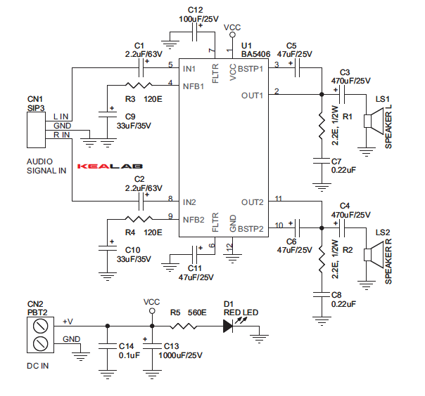
Schematic
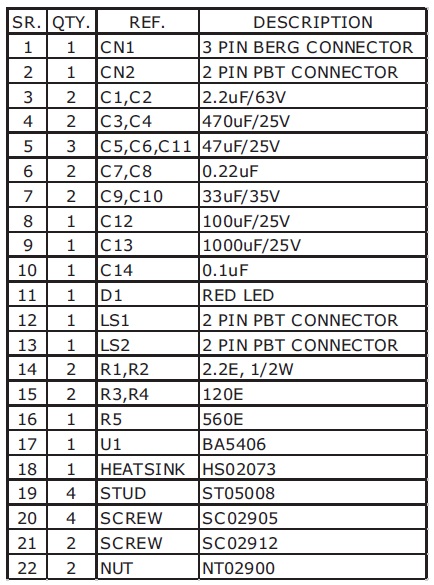
Parts List

This project is a 20W Audio amplifier based on LM1875.
Description
This project is designed to operate with a minimum of external components. This amplifier offers high-quality and high-performance audio at very low distortion. The project is based on National’s LM1875 IC. The IC is thermal and short circuit protected.
The LM1875 is a monolithic power amplifier offering very low distortion and high quality performance for consumer audio applications, the project work on single supply. Device overload protection consists of both internal current limit and thermal shutdown.
The LM1875 design takes advantage of advanced circuit techniques and processing to achieve extremely low distortion levels even at high output power levels. Other outstanding features include high gain, fast slew rate, a wide power bandwidth, large output voltage swing, high current capability, and a very wide supply range. The amplifier is internally compensated and stable for gains of 10 or greater.
Specifications:
- Supply 16-48V DC @ 2 Amp
- Output 20W into 4Ohm Speaker.
- Gain 26dB.
- Frequency Response 20Hz-20Khz
- Thermal Protection with parole circuit
- Low distortion: 0.015%, 1 kHz, 20 W
- Line Level audio signal Input
Distortion:
The preceding suggestions regarding circuit board grounding techniques will also help to prevent excessive distortion levels in audio applications. For low THD, it is also necessary to keep the power supply traces and wires separated from the traces and wires connected to the inputs of the LM1875. This prevents the power supply currents, which are large and nonlinear, from inductively coupling to the LM1875 inputs.
Power supply wires should be twisted together and separated from the circuit board. Where these wires are soldered to the board, they should be perpendicular to the plane of the board at least to a distance of a couple of inches. With a proper physical layout, THD levels at 20 kHz with 10W output to an 8Ωload should be less than 0.05%, and less than 0.02% at 1 kHz.
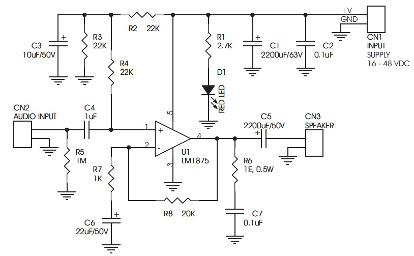
Schematic
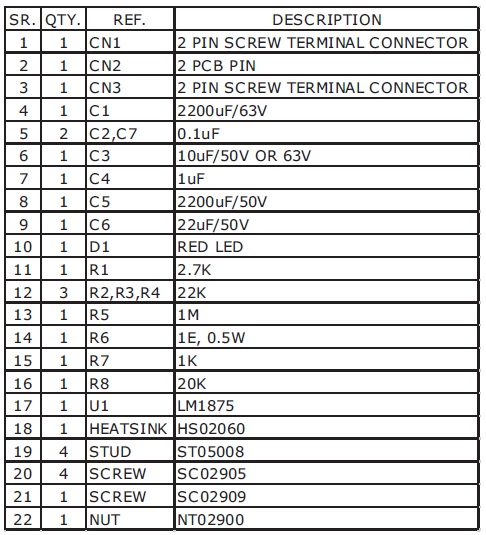
Parts List

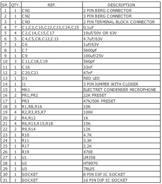
This project is a Voice echo module with build-in amplifier and on-board mic.
Description
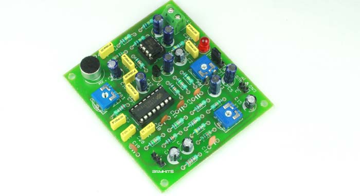
A project has been designed around Holteks Ht8970 voice echo IC. Project can be used in various audio systems karaoke, toys, animatronics, show, display, exhibitions, and sound equipments.
The HT8970 is an echo/surround effect processor. It is designed for various audio systems including karaoke, television, sound equipments, etc. The chip consists of a built-in pre-amplifier, VCO or Voltage Control OSC, 20Kb SRAM, A/D and D/A converters as well as delay time control logic.
Specifications:
- Supply Input 5V DC
- Onboard MIKE and Aux audio input
- MIKE and Aux and selection via jumper
- Input/MIKE signal level adjustable via preset
- It can work in two modes – echo or surround
- Output signal level adjust via preset
- Onboard preset for sound delay
- Onboard LED for power supply indicator
- Four mounting holes of 3.2 mm
- PCB dimensions 79 mm x 70 mm
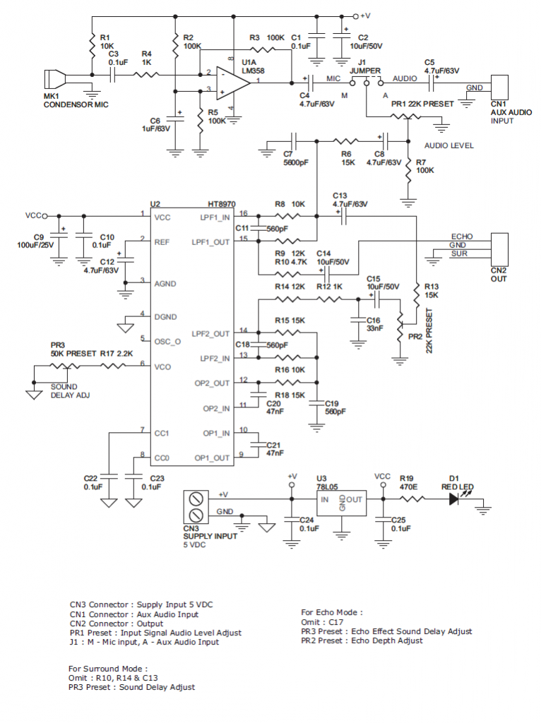
Schematic
Parts List
