Digitally Controlled 2.1 Channel Analog Audio Power Amplifier

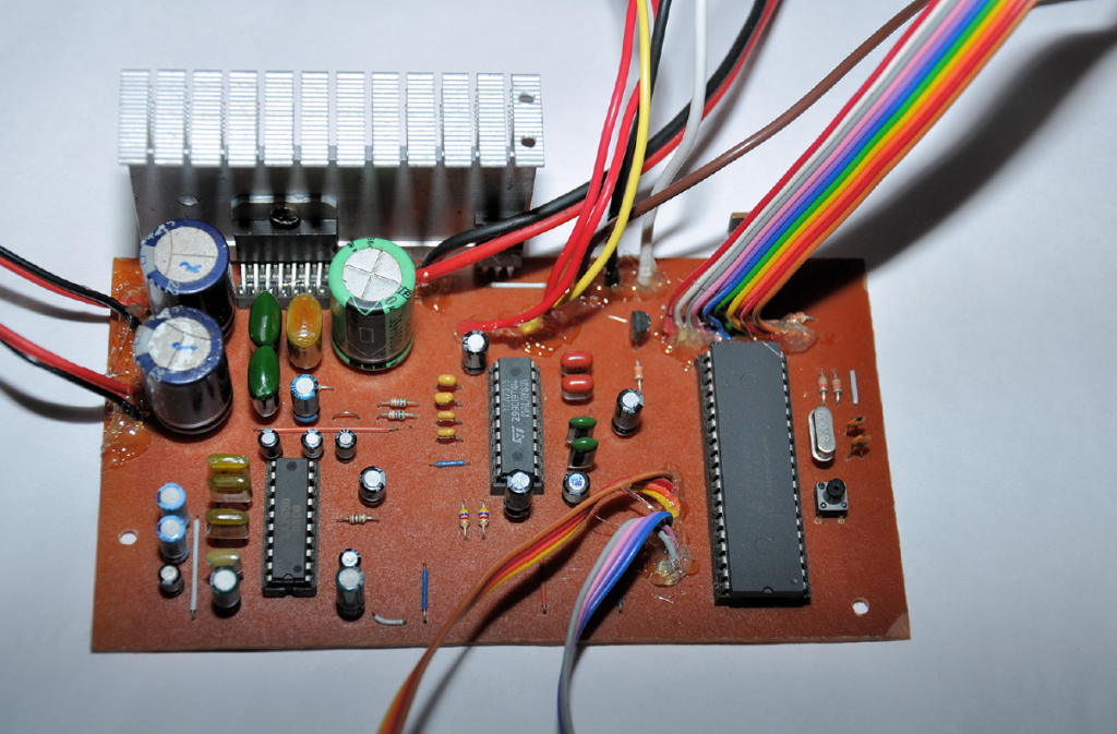
This article introduces high quality digitally controlled 2.1 channel analog audio power amplifier system. This project is mainly based on TDA7377 AF power amplifier and PIC18F452 8bit microcontroller. Basic technical features of this receiver are covered in table1.

This unit is specifically design to work with PC sound cards, radio receivers and CD/DVD/Blue-Ray players.

image-1

Construction

This system use commonly available electronic components and substitute components can also use.

For maximum quality we recommended to use components from same manufacturer. For example some actual capacitor values and resistor values are slightly varied from manufacture to manufacturer, and this cause some minor unbalances in output of amplifiers. When soldering the PCB we suggested to soldering small components such as jumper wires, resistors first and moving to larger components at last.

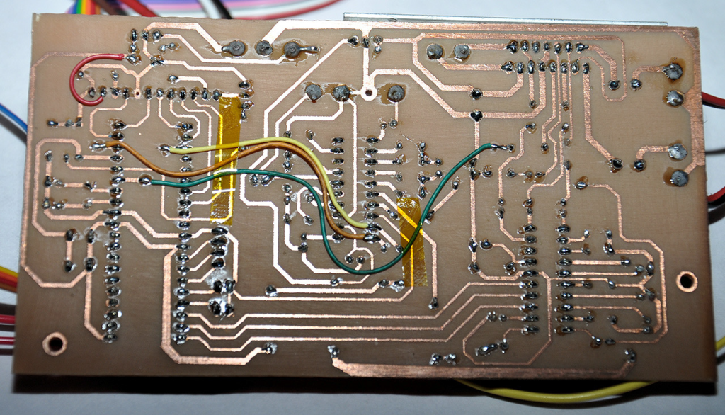
Also try to use IC sockets for all the DIP and TDA7377 ICs. In our prototype all the integrated circuits except 2 voltage regulators (IC5 – 7805 and IC6 – 7808) are connected to mainboard via IC sockets. All the controls, I/O and power terminals and display modules are connected to mainboard through wires, and for control and display lines we recommended to use suitable ribbon cables. For power and output wires 18-20 gauge multi-strand cables are recommended (these wires are commonly used for automotive wirings). In given PCB design 4 wires need to be installed for I2C bus and MCU STAND-BY lines. For this, standard Teflon coated 32-30 gauge wires are sufficient.

Microcontroller firmware and source code

This project is an open hardware project and all the source codes of PIC18F452 MCU are available to download at project website. The source code of PIC18F452 is written using MikroC for PIC compiler and free version of this compiler is available to download at Mikroelektronika[1] home page. Currently available firmware is design for 8MHz clock and other required MCU related settings are listed in table 2. Compiled HEX file for PIC18F452 is also available  to download at project website.

image-3

[1]:   Mikroelectronika home page is http://www.mikroe.com. MikroC for PIC is available to download at  http://www.mikroe.com/mikroc/pic

Testing the system

After assembling the system it is necessary to check all the power connections are working properly in this system. To check power lines follow the steps in below:

  1. Connect both AGND and DGND together and from here onwards this connection is referred as GND.
  2. Unplug TDA7377, TDA7315, LA2650, PIC18F452 and 1602 LCD module from the mainboard.
  3. Disconnect any audio inputs and outputs.
  4. Supply 12V – 14V DC input to GND and V+ lines.
  5. Check the voltages between IC pins which are listed in table3.

If voltage readings are correct, plug all the ICs and LCD module and hold down the SYSTEM-RESET button and apply power to the system. While holding the SYSTEM-RESET button press.

POWER ON/OFF button and turn on the system. Once you got the LCD on, release the SYSTEM-RESET button and adjust the controls and check the audio outputs. After firmware update or at initial run, pressing the SYSTEM-RESET button is essential to avoid any damages to speakers due to high volume levels.

image-5

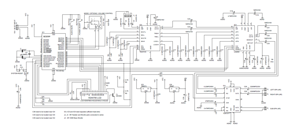
Schematic

Firmware

image-6

Parts List

image-7

Troubleshooting 

The most common problem can occur in this amplifier system is no audio from the power amplifier IC. The most possible reasons are excess supply voltage (which is above 18V) or short circuits in output terminals of amplifier. TDA7377 is equipped with several protection features and state of the protection system can be monitored through Pin 10 of TDA7377 IC.

Second most common issue is LCD with 16×2 boxes. This occurs due to initialization problems of HD44780 controller. A common reason for this issue is wrong wiring or faulty PORTD outputs.

If LCD output is too light (or dimmed), change the value of R1 (2.2KΩ) resistor. We set this value for commonly available Blue/White 1602 LCD module.

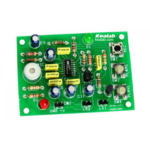
60 seconds Voice Record – Playback module

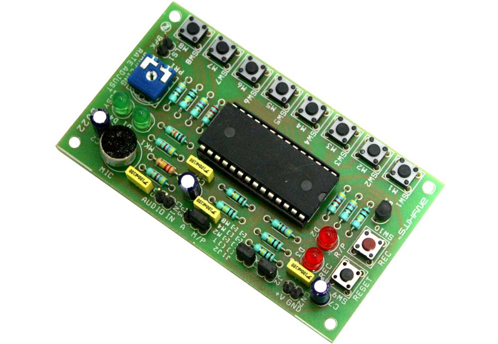
This project is a 60 seconds voice record – playback module.

Description

Voice Module 60 Sec project will playback and record up to 60 seconds of voice message.  This circuit  is an excellent choice to add voice to your project.

Specifications:

  • Up to 60 Seconds of nonvolatile voice storage
  • Up to eight segments record and play option available
  • Easy and clear, jumper selectable mode option
  • Preset for adjusting sampling rate
  • Tactile switches for Record, Play function trigger
  • Easy jumper selection for selecting recording source
  • Onboard microphone for recording message directly onto the chip
  • Audio output available to drive a speaker
  • Direct speaker connection via berg connector
  • LED to display Record/Playback of messages
  • Berg connector for power supply input
  • Four mounting holes of 3.2 mm each
  • PCB dimensions 54 mm x 94 mm

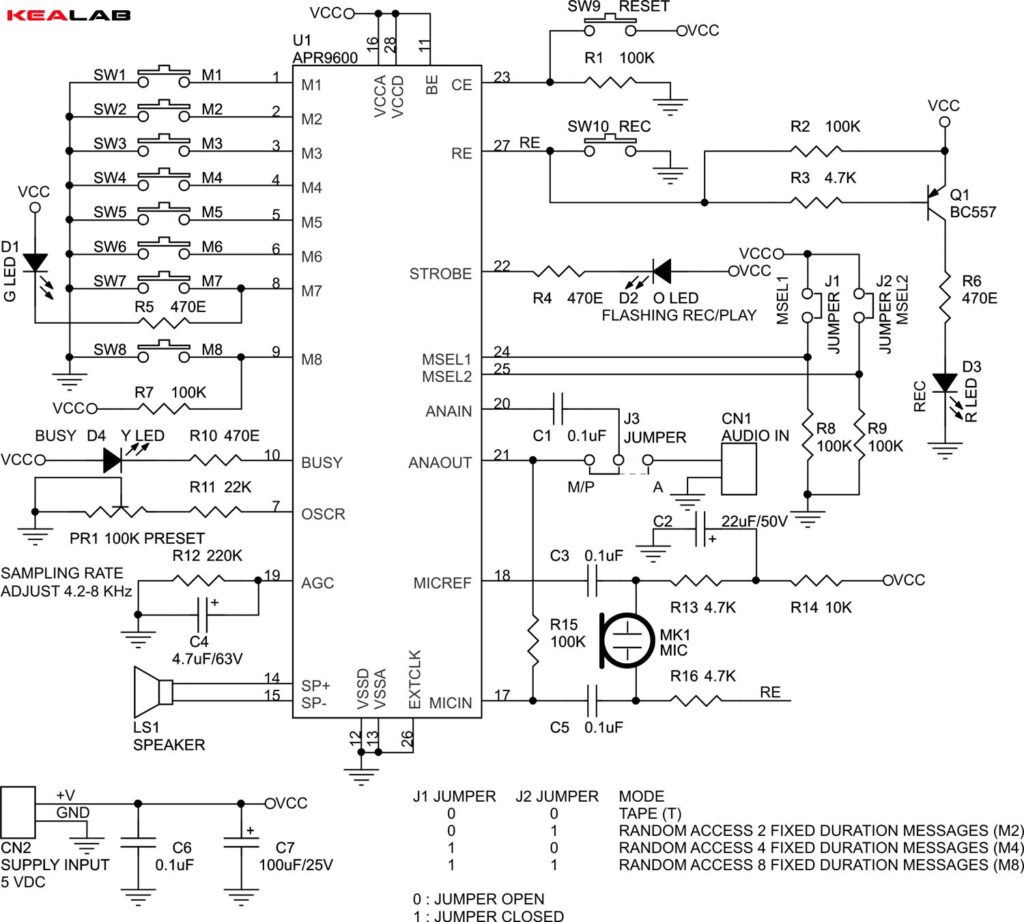
This circuit will help you record and play a 60 seconds voice message stored on it.  This circuit is based on APR9600 IC from Aplus.

The project provides four different modes of voice message to be recorded and played, viz i) MOD8 : 60 Seconds is equally dived in 8 equal segments, ii) MOD4 : 60 Seconds is equally divided in four equal segments, iii) MOD2 : 60 Seconds is equally divided in two equal segments and iv) Tape Mode : Entire 60 segment is available in a single shot mode.  For MODE selection see MODE selection table.

There are two different ways to record a voice message onto the chip viz. i) CN1 connector on PCB for external audio input or ii) Onboard Microphone.  Jumper J3 on the PCB to select audio source.  J3-Position A would select the external audio input and J3-Position M/P would select onboard microphone.  Onboard preset PR1 will adjust the sampling rate of playback and record option for IC.  Important thing to remember is that, if you increase the sampling rate, the duration of message will reduce and vice-versa.  For details see resistance values & sampling frequencies table.

Recording a Message:

To record a message, please select the right MODE at Jumper J1 and J2.  The MODEs are clearly marked on the PCB and jump or no-jump positions are also marked.  Also select the source for recording through CN1 Connector.  Keep the sampling rate preset PR1 in the middle position to test a sample of the recorded message.  Increasing the sampling rate will decrease the total amount of recording time and vice-versa.

MODES:

MOD8: This MOD allows you to record a message in 8 equal location available through switches SW1 to SW8 (M1 to M2).  To record a message in any on of this location, you need to keep the Record Switch SW10 pressed with one finger and the Segment Switch pressed.  A Pip sound will play through the speaker to denote recording start.  Recording will end when you release both these keys and when it reaches the end of the segment.  Another PiP would sound to denote the end of recording.  Switches marked M1 to M8 are available in this mode.

MOD4: The procedure is the same as described above in MOD8, and the keys available in this mode are M1 to M4.

MOD2: The procedures is the same as described above in MOD8, and the keys available in this mode are M1 and M2.

TAPE MODE: The procedure is the same as described above in MOD8, and only M1 key is available in this mode.

Playing a Message: Connect a appropriate speaker (should not lower than 8 Ohms) at LS1, For playing a recorded message you just need to press and release any of the switch available in that particular mode once.  The play of message is also indicated by the flashing of LED, D2.

Reset Switch: Switch SW9 is used to reset the EOM, End of Message marker position to the start of the message in the Tape Mode of operation.

Schematic

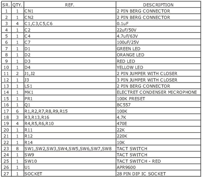
Parts List

60_SEC_VOICE_RECORC_PLAYBACK_BOM_th

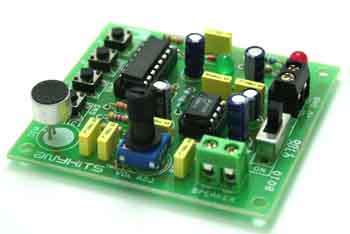
3 Tone Musical Bell

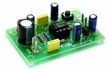
MUSICAL_BELL_PIC

This project is a 3 tone musical bell.

Description

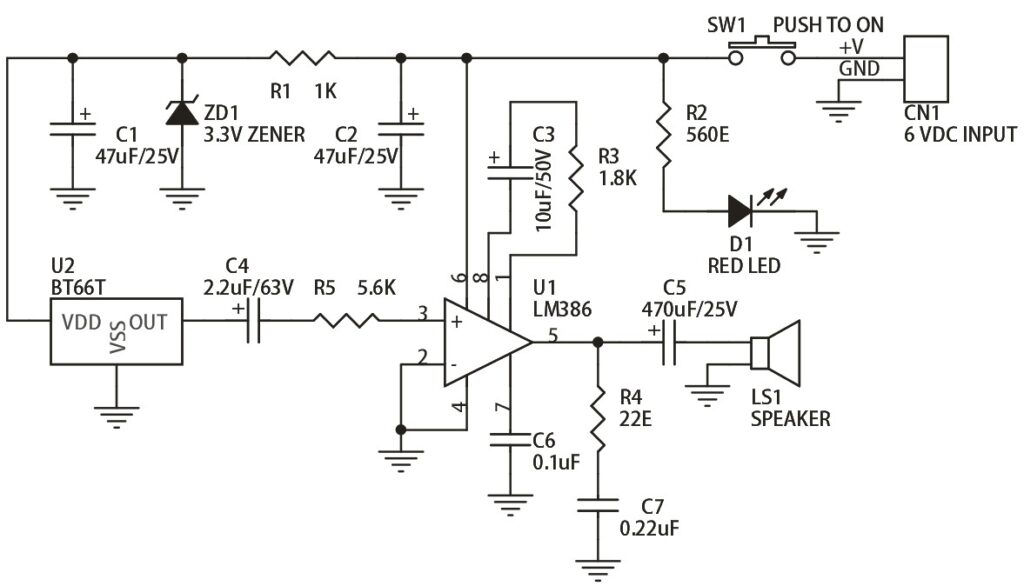
Tone Musical Bell is a project built around BT66T (UM66) IC driving, LM386 has been used as audio amplifier to give extra punch.

Specifications:

  • Input 6 VDC @ 200 mA
  • Output 8 Ohms 0.5 W Speaker
  • Terminal pins for supply voltage and speaker connection
  • Power-On LED indicator
  • Onboard push to ON switch
  • Four mounting holes of 3.2 mm each
  • PCB dimensions 35 mm x 54 mm

CN1 – DC Supply Input
LS1 – Speaker Output
SW1 – Tactile Switch (Push to ON)
D1 – Power-ON LED Indicator

Schematic

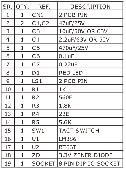
Parts List

MUSICAL_BELL_BOM

12W Audio Amplifier

12W_Amp

This project is intended for use as low frequency class AB audio amplifier.

Description

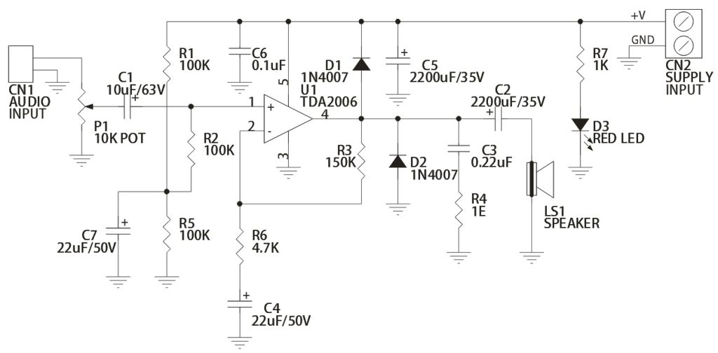
Project is built around TDA2006 PENTAWATT package. TDA2006 provide high output current and has very low harmonic cross-over distortion. Further the device incorporate- rates an original (and patented) short circuit protection system comprising an arrangement for automatically limiting the dissipated power so as to keep the working point of the output transistors within their safe operating area. A conventional thermal shutdown system is also included. The TDA2006 is pin to pin equivalent to the TDA2030.

Specifications:

  • 18V 2amps Single Supply
  • Power supply up to 18 VDC
  • Output power 12 W @ 4 Ω, 8 W @ 8 Ω
  • TDA2006 provides high output current
  • Has very low harmonic and cross-over distortion
  • Short circuit protection/Thermal shutdown system in IC
  • Terminal pins for connecting audio signal input
  • Header connector for connecting potentiometer (POT) for volume adjustment
  • Screw terminal connector for easy power supply input and speaker connection
  • Power-On LED indicator
  • Heatsink for IC
  • Four mounting holes of 3.2 mm each with nut and stud
  • PCB dimensions 51 mm x 63 mm

Schematic

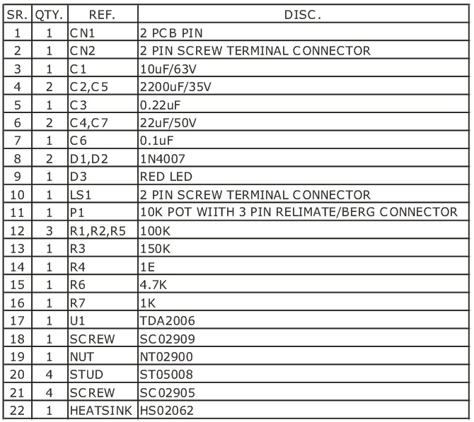
Parts List

12W_Amp_Bom

Voice Modulator (Sound Effects – Funny Sound)

VOICE_MODULATOR

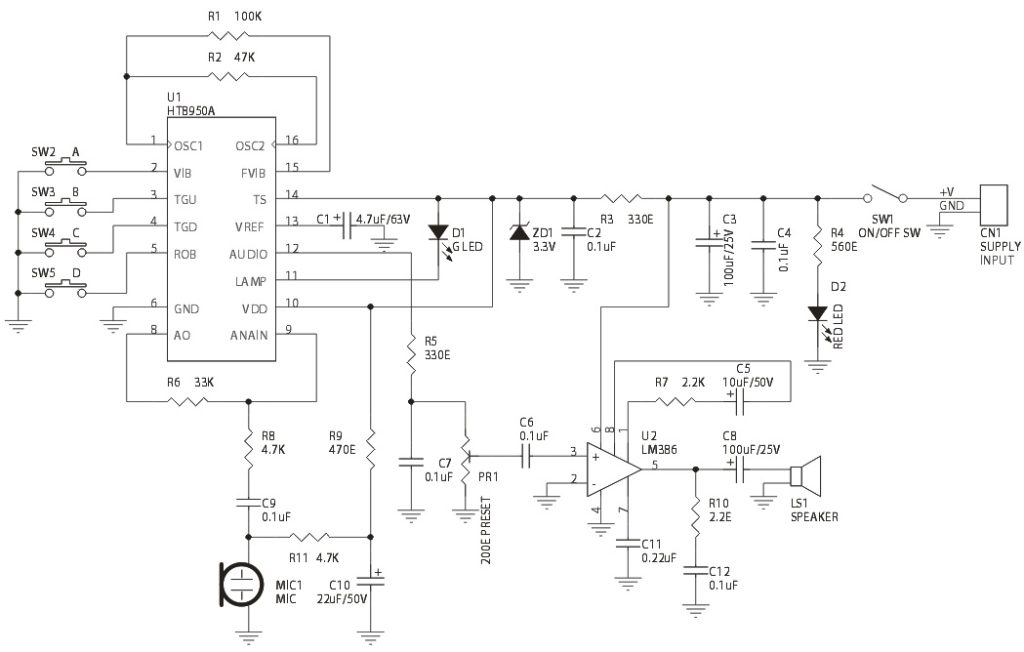
Voice Modulator project is designed around HT8950A to provide two special sound effects viz. Vibrato & Robot.

Description

This project  provides two special effects: vibrato and robot. The vibrato effect is generated by alternating the frequency of an input signal up and down at a rate of 8Hz. The robot function, on the other hand, converts an input voice into a robot voice. Both effects can be selected depending on which pin is triggered, either ROB or VIB. For the output frequency level shifting, the chips provide seven steps which can be selected from the two groups of pins namely, SW0, SW1 and SW2 for electronic direct selection and ROB, TGD, TGU and VIB for push button selection.

The HT8950 include a built-in microphone amplifier with an internal bias, an 8-bit A/D converter, a built-in SRAM as well as a current output type 8-bit D/A converter. The 8-bit A/D and D/A converters with a sampling rate of 8kHz ensures a high quality and high S/N ratio output voice. The chips provide an LED indicator which flashes in accordance with the volume of the input voices.

Specifications:

  • Input – 6 VDC @ 300 mA
  • Output – Speaker, 8 Ω / 0.5 W
  • 7 Step level shifting (Volume Control) SW3 (TGU) and SW4 (TGD)
  • SW2 – Vibrato mode, SW5 – robot mode
  • LED to display the voice level input
  • ON/OFF slide switch for power supply
  • Audio amplifier type LM386 with volume control preset
  • PBT (Power Battery Terminal) connectors for supply voltage and speaker output
  • Power-On LED indicator
  • PCB dimensions 63 mm x 68 mm

CN1 – 6 VDC Supply Input
MIC1 – Electret Condenser Microphone
LS1 – Speaker

Schematic

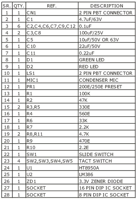
Parts List

VOICE_MODULATOR_BOM

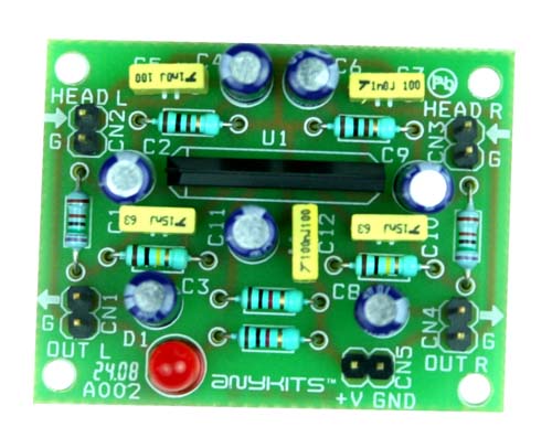
Tape Head Pre-Amplifier

Tape_Head_Pre-Amplifier_A

This project is a tape head Pre-Amplifier circuit.

Description

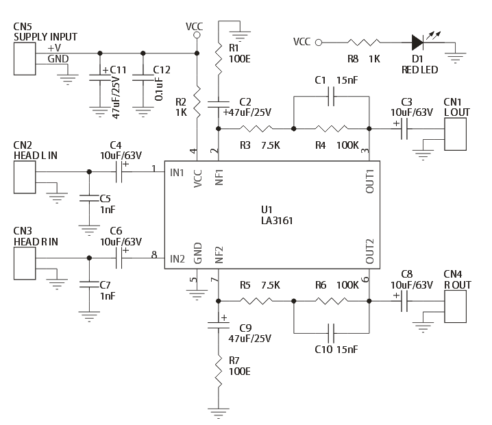
The circuit is built around a popular Sanyo’ stereo head preamp IC LA3161. Low electrical signals from the playback heads are fed to pins 1 and 8 of IC1 via DC decoupling capacitors, respectively. Components between pins 2 and 3 and pins 6 and 7 provide adequate equalization to the signals for normal tape playback.

Specifications:

  • Power supply: 9 ~ 12 VDC @ 20 mA
  • Output power: up to 200 mW
  • Input Resistance – 100 KΩ (Typ), Load Resistance – 10 KΩ (Typ)
  • Low noise, good ripple rejection owing to the on-chip voltage regulator
  • Berg pins for connecting power supply, input and output
  • Power-On LED indicator
  • Four mounting holes of 3.2 mm each
  • PCB dimensions 49 mm x 38 mm

Schematic

Tape_Head_Pre-Amplifier_B

Parts List

Tape_Head_Pre-Amplifier_E

LA3161 Datasheet

120 Seconds Voice Record – Play Back

B002

This project is a message recording board capable of recording 120 secs of audio.

Description

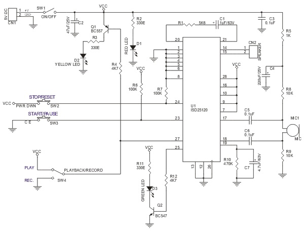
This project is designed around ISD25120 which can store 120 Seconds audio. Recording and playback operations are controlled with tact switches. The kit has an onboard microphone and LED to indicate the functions of Play and Recording. IC has a re recordable non-volatile memory which means that the message will be stored even after the units are turned off and even when it is turned on again.

Specifications:

  • Input supply – 5 VDC @ 120 mA
  • Output – speaker, 16 Ω
  • Upto 120 Seconds of non volatile voice storage
  • Slide switch for easy selection of Playback / Record mode
  • Onboard MIC capsule for recording message directly onto the chip
  • Flashing LED to display Record / Playback of messages
  • ON Board ON/OFF Switch
  • Power-On LED indicator
  • Direct speaker connection via Header Connector
  • Header type connector for power supply input
  • 4 pin small tactile switches for Start / Pause and Stop / Reset
  • Four mounting holes of 3.2 mm each

Schematic

ISD SCH

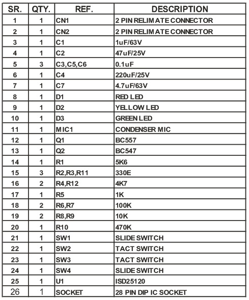
Parts List

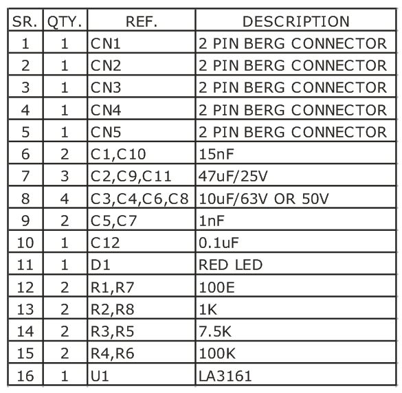
BOM ISD

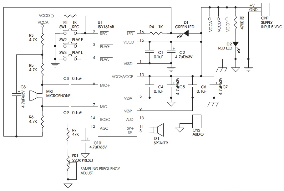
20 Seconds Voice Record – Playback

001_photo

This project is a message recording board capable of recording 10 to 20 secs  depending on audio quality.

Description

This project has been designed around Winbond’s ISD1616 IC (SMD) IC, which is fully integrated, single-chip, single message voice record and playback device ideally suited to a variety of electronics systems, Message duration is user selectable in ranges from 10 to 20 Seconds depending on the sampling rates from 4 KHz to 12 KHz adjustable via preset, giving the users greater flexibility in duration versus recording quality.

Applications:Toys, Amusement Equipment’s, Interactive Games, Lifts/Escalators, Warning Systems, Security Systems, Audio Guide, Home Appliances, Robotics, Animatronics, Light and Sound Show .

Specifications:

  • Power supply input 5 VDC @ 100 mA
  • Power supply spans a range from 2.4 to 5.5 VDC
  • Standby current 1 uA typical and 10 uA maximum without power LED
  • Enters standby mode immediately after record playback cycle
  • Microphone preamplifier with automatic gain control built in IC
  • PWM Class D speaker driver
  • Speaker 8 Ohms
  • Onboard microphone
  • Easy operation via onboard tact switches
  • Onboard tact switches for Level trigger Play, Edge trigger Play, and Recording
  • Onboard power indication
  • Onboard preset for sampling rates settings
  • Onboard recording indication
  • Supply input and speaker terminal via berg connector
  • Low Noise high quality voice record/playback
  • 100 Year massage retention
  • 100,000 record cycles
  • Speaker is not provided with kit

Schematic

001_Schematic

001_Details

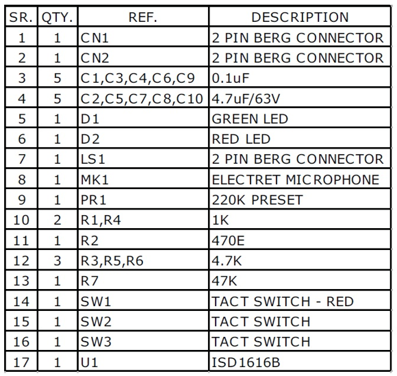
Parts List

001_BOM_th

RIAA Corrector

photo_1_th

Description

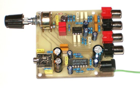
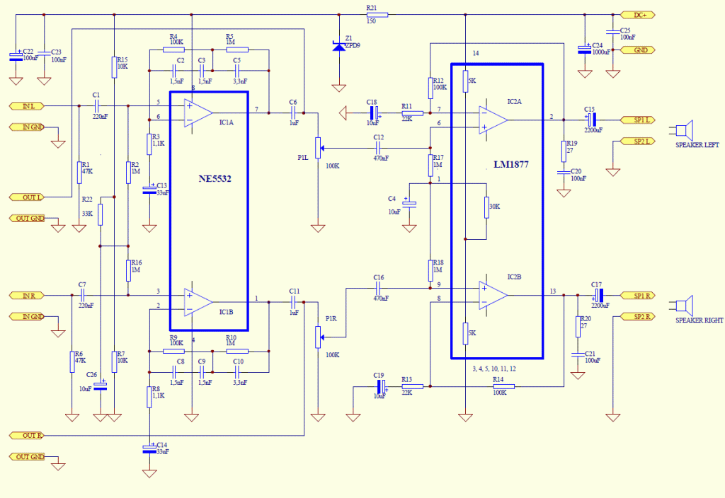
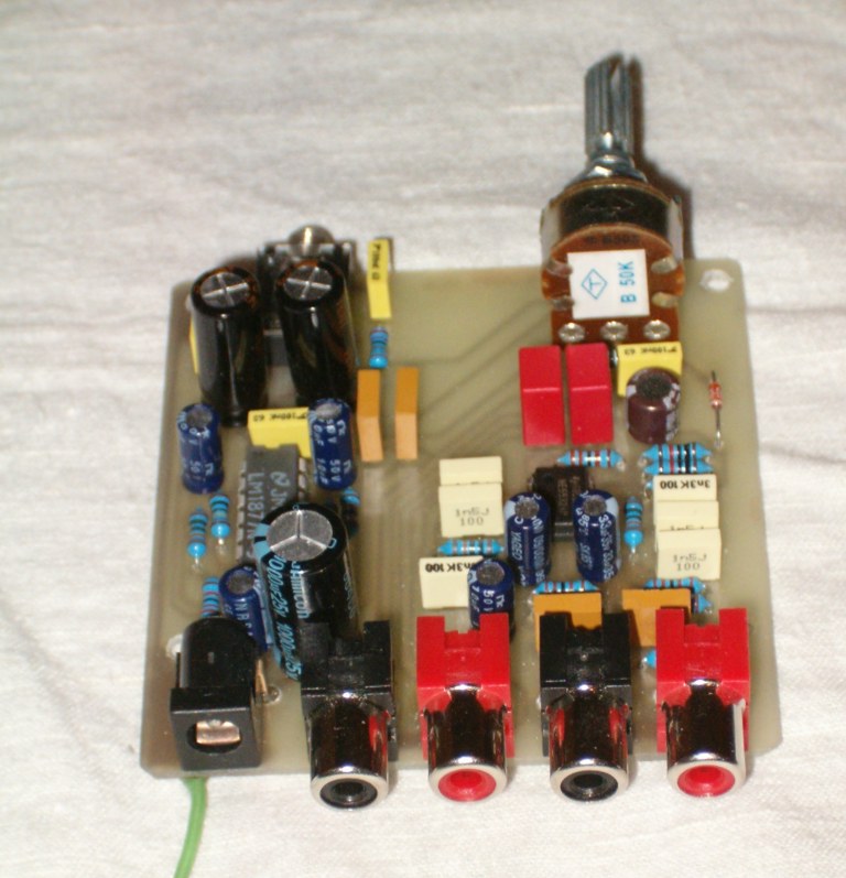
To listen old vinyl LP’s in a correct sounding on a sassy with dynamic cartridge you need a circuit, named RIAA corrector. This circuit you can find in old amps, but it isn’t embedded in home cinema equipments or amplifiers can be obtained nowadays. Also, if you want to archive your vinyl LP’s in your computer it is necessary to use this RIAA corrector. It is good, if this corrector has a little built-in amplifier to drive small control speakers, or earphones. Schematic of circuit  built for this express purpose can be found hier. It has two parts, corrector and amplifier part.

The corrector part contains NE5532 integrated circuit with extreme small noise. Resistors are 1% metal film 0,6W types, condenser’s of this corrector section must be 5% or better, 63 – 100 V types. Corrector section has direct output to external amp or computer. Amplifier section contains integrated amp IC LM1877. It deliver to speakers 2W/channel output power with very low distortion. Potentiometer P1 is for control the output power of the amp section.

The whole circuit works from external 12-16 V DC supply. Schematic, photos and PCB layout of the circuitry can be found attached. Short mathematics description of RIAA curve and basics of LP’s production also can be found in attached document.

Schematic

schematic

Parts List

Photos

photo_2

RIAA Curve

LP’s are engraved with reduced bass levels and increased treble levels.

For the same sound level, a low frequency requires a larger groove which gives two drawbacks:

– Less recording time
– Difficulties for the cartridge to follow it and thus, higher distortion

At the other end of the spectrum, the contact between the stylus and the groove makes noise, a high frequency noise. By increasing the high frequencies level during recording we can obtain a better signal/noise ratio as the noise is reduced by the playback curve.

Several other curves did exist before the RIAA but it replaced them completely during the 60′.

Here is the formula to obtain the original RIAA curve:

image_1
Where:

N=level in dB
f=frequency
t1=treble time constant, 75uS
t2=medium time constant, 318uS
t3=bass time constant, 3180uS

In 76′, IEC introduced a modification of this curve by introducing a new time constant that modifies only the extreme bass. It is known as the RIAA/IEC curve.
This correction has never obtained a big success, the original RIAA curve is still the most widely used.
For information, here is the formula:

image_2

Where: t4=extreme bass time constant, 7950uS

The RIAA reproduction curve:

image_3

Hz RIAA IEC
20 19.36 16.35
22 19.24 16.62
25 19.04 16.89
28 18.83 17.04
31 18.61 17.09
35 18.29 17.06
39 17.96 16.95
44 17.54 16.73
49 17.12 16.45
55 16.61 16.07
62 16.02 15.59
70 15.37 15.03
79 14.67 14.40
89 13.93 13.72
100 13.18 13.01
110 12.54 12.39
120 11.94 11.82
130 11.38 11.27
150 10.36 10.28
170 9.46 9.40
190 8.67 8.62
210 7.97 7.93
240 7.04 7.01
270 6.25 6.23
300 5.57 5.55
340 4.80 4.79
380 4.16 4.15
430 3.49 3.48
480 2.93 2.92
540 2.38 2.38
610 1.86 1.86
680 1.43 1.43
760 1.02 1.02
850 0.63 0.63
950 0.26 0.26
1100 -0.23 -0.23
1200 -0.52 -0.52
1300 -0.79 -0.79
1500 -1.31 -1.31
1700 -1.80 -1.80
1900 -2.27 -2.27
2100 -2.73 -2.73
2400 -3.39 -3.39
2700 -4.04 -4.04
3000 -4.65 -4.65
3400 -5.43 -5.43
3800 -6.17 -6.17
4300 -7.02 -7.02
4800 -7.82 -7.82
5400 -8.70 -8.70
6100 -9.64 -9.64
6800 -10.50 -10.50
7600 -11.39 -11.39
8500 -12.30 -12.30
9500 -13.22 -13.22
11000 -14.44 -14.44
12000 -15.17 -15.17
13000 -15.85 -15.85
15000 -17.07 -17.07
17000 -18.14 -18.14
19000 -19.09 -19.09
21000 -19.95 -19.95


TOP PCB Companies