
Description
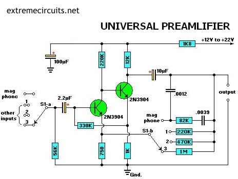
Most audio amplifier systems must have preamplifiers with many different characteristics. These include high-gain linear response for magnetic microphones, low-gain linear response for tuners, and high-gain RIAA equalization for magnetic phone cartridges.
To meet this broad requirement, most amplifier designers include a single universal preamplifier circuit. Basically a high-gain linear amplifier, its characteristics can be altered by switching alternative resistor filter networks into its feedback system.
For example, when the selector switch is set to the Mag phono position, alternative input sources can be selected by S1-a, and appropriate linear-response gain control feedback resistors 220K, 470K, and 1M are now selected by S1-b. Those feedback resistor values are selected between 10 kilo ohms and 10 megohms to suit individual listener tastes. Circuit gain will be proportional, to the feedback resistor value.

Description
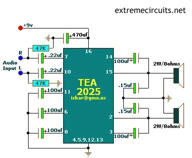
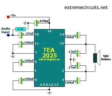
Above circuits are based on TEA2025 is a monolithic integrated audio amplifier in a 16-pin plastic dual in line package manufactured by UTC .Circuit has an Internal Thermal Protector. It is designed for portable cassette players and radios. You can also use it as your PC Audio Amplifier. A few external components required to build this circuit. Use 9v transformer to play the circuit. But not more than DC12v. Because it can damage the amplifier IC. So build n Enjoy.
Stereo per channel
VCC=9V;RL=4Ω/3W
VCC=9V;RL=8Ω/2W
Bridge Application
VCC=9V;RL=8Ω/5W
VCC=9V;RL=4Ω/8W
Specifications
Supply Voltage min = DC3v @ 500mA
Supply Voltage max = DC12v @ 500mA
Supply Voltage recommended = DC9v @500mA

Description
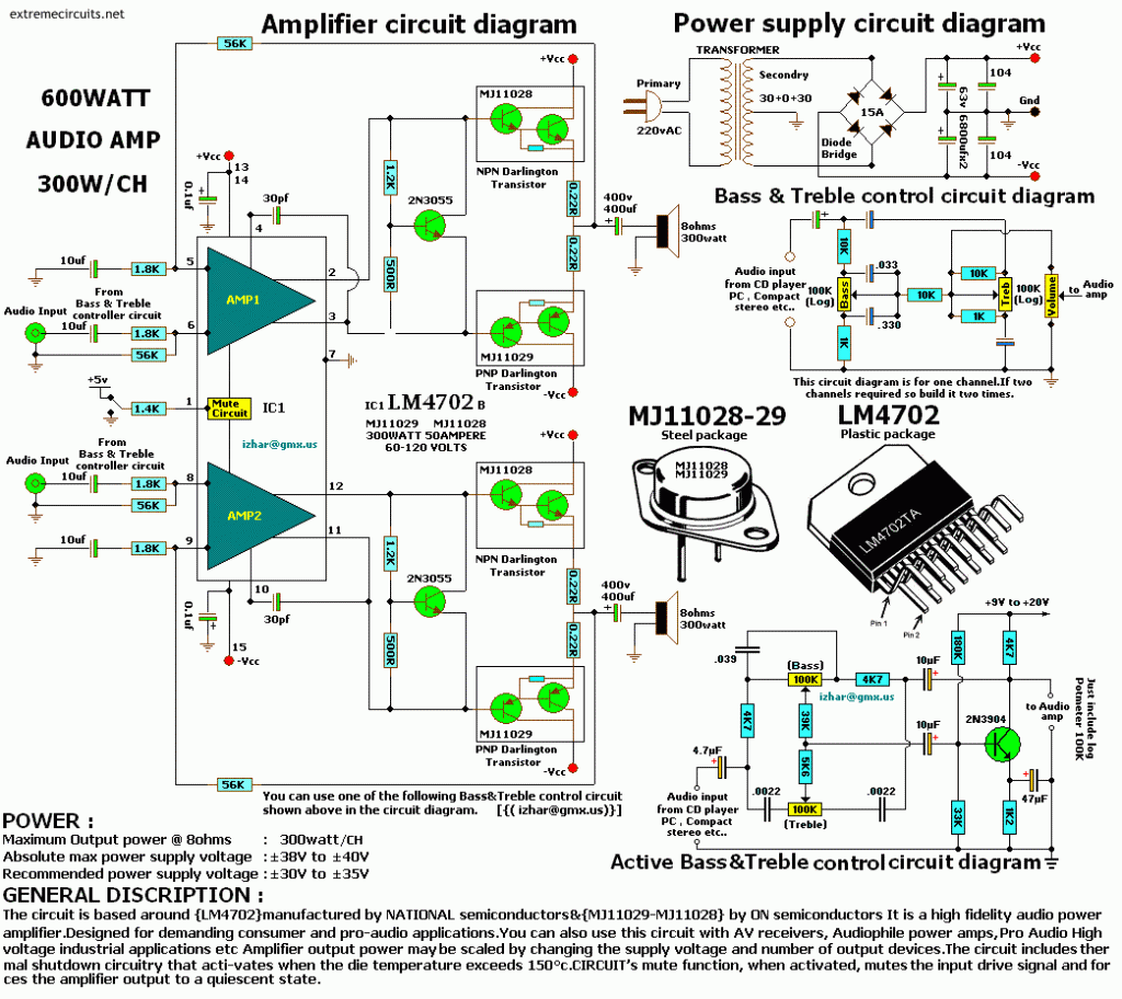
The circuit is based around {LM4702} manufactured by NATIONAL semiconductors & {MJ11029-MJ11028} by ON semiconductors It is a high fidelity audio power amplifier. Designed for demanding consumer and pro-audio applications. You can also use this circuit with AV receivers, Audiophile power amps, Pro Audio High voltage industrial applications etc Amplifier output power maybe scaled by changing the supply voltage and number of output devices. The circuit includes thermal shutdown circuitry that activates when the die temperature exceeds 150°c. CIRCUITs mute function, when activated, mutes the input drive signal and forces the amplifier output to a quiescent state.
Power
Maximum Output power @ 8ohms : 300watt
Absolute max power supply voltage :±38V to ±40V
Recommended power supply voltage :±30V to ±35V

Description
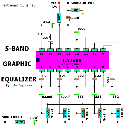
This complete high quality, low noise 5-BAND GRAPHIC EQUALIZER circuit is based around Monolithic Linear integrated circuit LA3600 manufactured by SANYO. This circuit is very easy to build and has good Quality. You can use it with Portable component stereos, tape-recorders, radio-cassette recorders, car stereos etc…
It is On-chip one operational amplifier. 5-band graphic equalizer for one channel can be formed easily by externally connecting capacitors and variable resistors which fix fo (resonance frequency). Series connection of two LA3600s makes multiband (6 to 10 bands) available. It is Highly stable to capacitive load. Maximum supply voltage VCC max 20V must not be exceeded. The operating voltage is in the range of 5 to 15V. Application of power with the pin-to-pin spaces shorted causes breakdown or deterioration of the IC to occur. When mounting the IC on the board or applying power, make sure that the pin-to-pin spaces are not shorted with solder, etc.

Description
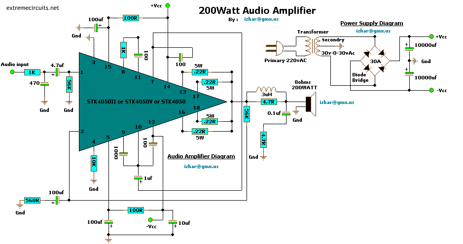
This complete high quality, low noise mono audio power amplifier is based around the Hybrid Integrated Circuit STK4050 manufactured by Sanyo. The circuit incorporates volume and has a maximum music output power of 200W. The circuit incorporates an on board power supply; therefore, only center tapped transformer is required to power the circuit. I t has very good quality sound. U can use it with your Home Theatre your PC & etc… You can also use it as Subwoofer Amplifier. It is a compact package for THIN-TYPE Audio sets. Easy Heatsink design to disperse heat generated in THIN-TYPE audio sets. Constant-Current circuit to Reduce supply switch-ON and switch-OFF shock noise. External supply switch-On and switch-OFF shock noise muting, Load short-circuit protection, thermal shutdown and other circuits can be tailored-designed.
Specifications
- Output Power : 200Watts
- Load Resistance : 8ohms
Input impedance : 55K
- Maximum supply voltage : (+95v)-0-(-95v)
- Recommended supply voltage : (+66v)-0-(-66v)

Description
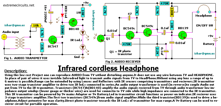
Using this low cost Project one can reproduce AUDIO from TV without disturbing anyone. It does not use any wire between TV and HEADPHONE. In place of pair of wires it uses invisible Infrared light to transmit audio signals from TV to Headphone. Without using any lens a range of up to 6 meters is possible. Range can be extended by using Lenses and Reflectors with IR sensors comprising transmitters and receivers. IR transmitter uses two-stage transistor amplifier to drive two IR leds connected in series. An audio output transformer is used (in reverse) to couple Audio output from TV to the IR transmitter. Transistors (BC547) & (BD140) amplify the audio signals received from TV through audio transformer low impedance output windings (lower gauge or thicker wire) are used for connection to TV side while high impedance are connected to the IR transmitter.
This IR transmitter can be powered by 9v mains Adaptor or 9v Battery. Led in transmitter circuit functions as power-on indicator. IR receiver uses 3-stage transistors amplifier. The first two transistors (BC549c)from audio signal amplifier. While the third transistor(BD139)is used to drive a headphone. Adjust potmetre for max clarity. Direct photo transistor towards the IR Leds of transmitter for max range. A 9v Battery can be used to receiver circuit for portable operation.

Description
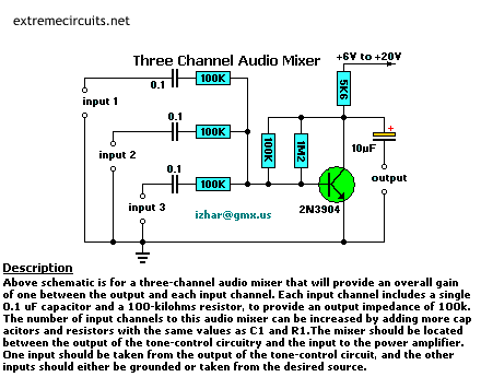
Above schematic is for a three channel audio mixer. That will provide an overall gain of one between the output and each input channel. Each input channel includes a single 0.1uf capacitor and 100-Kilohms resistor to provide an output impedance of 100K.
The number of input channels to this audio mixer can be increased by adding more capacitors and resistors with same value as capacitor(0.1uf) and resistor(100K). The mixer should be located between the output of tone control circuitry and the input to the power amplifier. One input should be taken from the output of the tone control circuit, and the other inputs should either be grounded or taken from desired source.
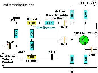

ACTIVE BASS TONE CONTROLLER circuit diagram
It is very useful (and has Best Quality) for 1 -100watt AUDIO AMPLIFIERS


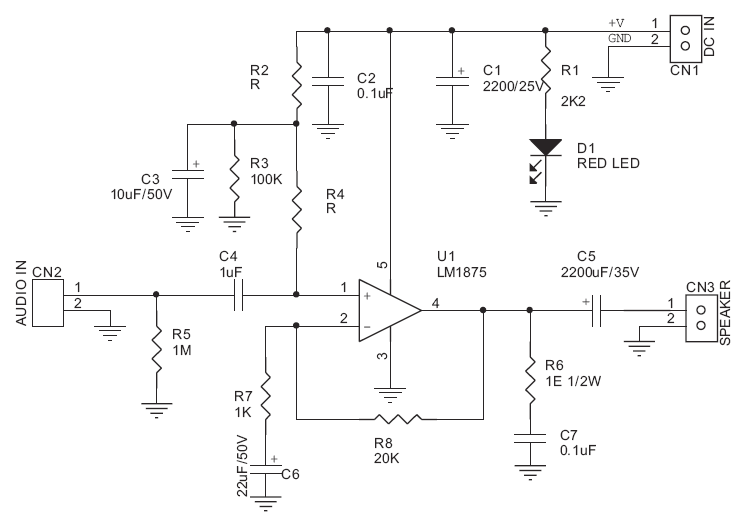
20W Audio Amplifier kit is based on LM1875 IC.
Specifications
- Power supply – 48 VDC
- Output – 20 W, 4 Ω
- Very low distortion (THD – 0.015%), good channel separation and ripple rejection
- IC built-in thermal, short circuit protections
- Internal output protection diodes
- Terminal pins for connecting input
- Power Battery Terminal (PBT) for easy power supply and speaker connection
- Power-On LED indicator
- Heatsink for IC
- Four mounting holes of 3.2 mm each with nut and stud
- PCB dimensions 48 mm x 60 mm
Schematic
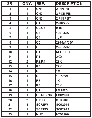
Parts List

Description
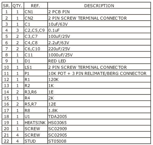
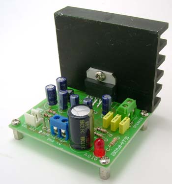
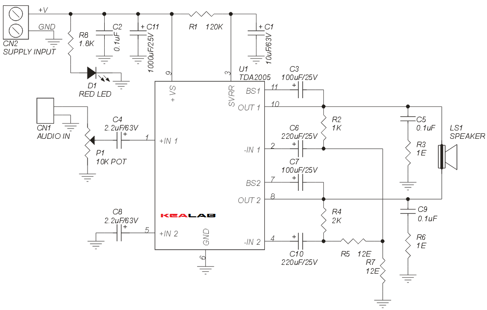
20W Bridge Audio Amplifier project, based on the TDA2005 IC, The TDA 2005 IC is class B dual audio amplifier, specifically designed for car radio applications etc.
Specifications:
- Power supply input : 18 VDC
- Output power : 20 W, 4 Ω
- IC built in Thermal Shut-down, Load dump voltage surge protected
- Terminal pins for connecting left and right audio signal inputs
- Berg Connector for connecting Potentiometer (POT) for volume adjustment
- Power Battery Terminal (PBT) for easy power supply and speaker connection
- Power-On LED indicator
- Heatsink for IC
- Four mounting holes of 3.2 mm each with nut and stud
- PCB dimensions 63 mm x 65 mm
- Note : Use shielded cable for connecting potentiometer
Schematic
Parts List
