Scintil Photonics demonstrates first single chip 100 GHz DFB Comb Laser Source at OFC 2023

High-performance computing and AI applications set to gain improved computing system performance and power efficiency through Scintil’s multi-port comb laser

Scintil will also present: ‘Fully Integrated III-V-on-Silicon Multi-Port DFB Laser Comb Source for 100 GHz DWDM’ during OFC, San Diego (CA), taking place March 5 – 9

Grenoble, France, March 1, 2023 – Scintil Photonics, a leading innovator in silicon Photonic Integrated Circuits (PICs), will demonstrate its latest technology, a single-chip multi-port 100 GHz DFB (Distributed FeedBack) Comb Laser Source for high-performance computing and AI applications, at booth #3351 during OFC 2023.

Named SCINTIL Comb Laser Source, this is the first fully integrated single chip that achieves 100-GHz frequency spacing, which is half to one-quarter of the spacing available today. One of its key advantages is its very narrow controlled channel spacing, an important capability for increasing the number of optical carriers in a single fibre.

“We are thrilled to showcase our latest innovation, a 100 GHz DFB Comb Laser, at OFC 2023,” said Sylvie Menezo, CEO of Scintil Photonics. “Increasing computing capacity requires connecting larger networks of computing units with higher transmission rates. In order to achieve this with sustainable energy efficiency, fiber optic transmission links are used with multiple optical carriers multiplexed on one single fiber. We have succeeded in implementing a comb laser source with only 100 GHz spacing between each optical carrier. This offers at least twice the number of optical carriers compared to what appears to be available today, and therefore enables doubling the transmission speed. Leading customers are currently evaluating our solution.”

The increasing demand for high-performance computing and AI applications has led to the need for faster and more efficient optical interconnects. The SCINTIL 100GHz-Comb Laser Source enables the use of uncooled Dense Wavelength Division Multiplexing (DWDM) links in short reach transmissions, with optical carriers twice as dense (100 GHz versus 200 GHz spacing).

“The Scintil integrated team did an excellent job at every step, from the design of the chip to the packaging and the electronics for a complete solution, with additional locking functions. Thanks to our CMOS commercial foundry, we anticipate ramping up volume by Q4, 2024. We think that our technology will be a game-changer in the field of interconnects for high-performance computing and AI applications,” Menezo added.

Technical features

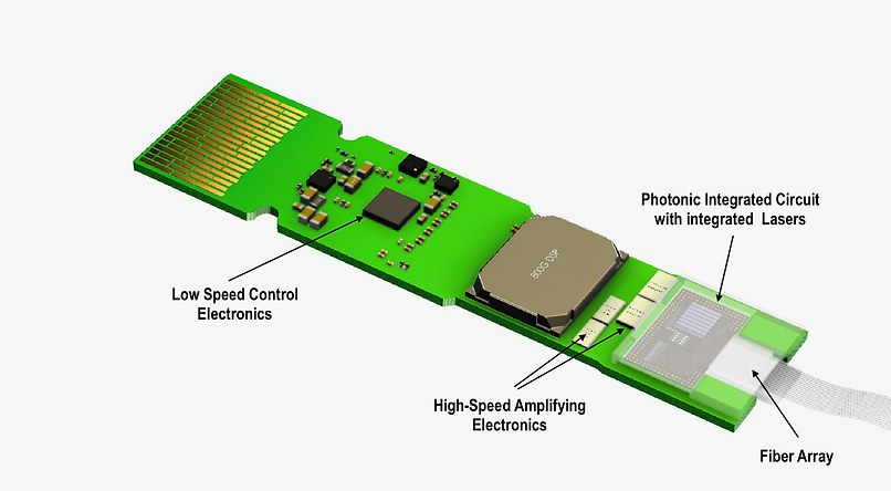
The DFB comb laser source is designed to fuel optics co-packaged with host ASICs. It features:

  • Multiple optical carriers spaced by 100 GHz and all combined and available on either one or multiple output ports
  • Configurations that can offer transmissions of 16 optical carriers x 64 Gbps per fiber, which are suitable to support next generation optical compute interconnect links
  • Easy locking capabilities, providing  system makers with unmatched characteristics for control and performance

Demonstrators are already available and product prototypes will be ready by the end of Q4, 2023.

Scintil will run demonstrations of its DFB Comb Laser Source with 100 GHz spacing at booth #3351, March 7 to 9. Please reserve a meeting slot, here.

The Scintil team will also present a paper entitled: ‘Fully Integrated III-V-on-Silicon Multi-Port DFB Laser Comb Source for 100 GHz DWDM’ on Monday, March 6, 2023, at 17:30 – 17:45 (PT) in M4C.5, room 3.

In other developments, Scintil is expanding its Grenoble office with current openings for a CFO with administrative functions, a senior product development engineer and a semiconductor packaging engineer.

About Scintil Photonics

Scintil Photonics develops and markets silicon Photonic Integrated Circuits (PICs): integrated laser arrays, multiples of 800 Gbit/sec transmitters and receivers, tunable transmitters, and receivers, as well as optical I/O for near chip and chip-chip communication. Its circuits are fabricated on a proprietary III/V-Augmented silicon photonics technology manufactured in a multi-customer silicon foundry. For accelerated adoption, the company also delivers the control electronics and reference package implementations. Based in Grenoble, France, and Toronto, Canada, Scintil is currently taking its innovative product to industrial level as it gears up for mass production.
www.scintil-photonics.com

Rohde & Schwarz showcases its state-of-the-art test solutions for embedded systems

Embedded systems are at the core of today’s electronic devices, whether in consumer electronics, telecommunications, industrial, medical, automotive or aerospace applications. Flawless operation is crucial, and engineers face complex challenges when designing ever more compact embedded systems that meet today’s demands of efficiency, safety, reliability and interoperability. Rohde & Schwarz addresses these challenges with its wide-ranging test and measurement solutions showcased at the embedded world Exhibition & Conference 2023 in Nuremberg.

Rohde & Schwarz brings its latest test and measurement solutions for the embedded industry to embedded world Exhibition & Conference. At the company booth 4-218 in hall 4 of Nuremberg Exhibition Centre, visitors can learn straight from the experts about various testing aspects for embedded designs: such as testing digital design and interfaces, power electronics, electromagnetic compatibility, wireless connectivity and in-vehicle networks.

Next generation oscilloscope for accelerated insight

The Rohde & Schwarz booth spotlights the new R&S MXO 4 series, the first in a new generation of oscilloscopes. The four-channel oscilloscopes feature a brilliant 13.3” full-HD capacitive touchscreen, while delivering a number of industry firsts: The R&S MXO 4 has the fastest real-time update rate of 4.5 mil waveforms/s, letting development engineers see more signal details and infrequent events than with any other oscilloscope. The 12-bit ADC has 16 times the resolution of traditional 8-bit oscilloscopes at all sample rates. And a standard acquisition memory of 400 Mpoints on all four channels gives them 100 times the standard memory. At embedded world, visitors can experience the R&S MXO 4 first-hand in a serial protocol and decode setup, showcasing its new CAN XL trigger and decode capability.

Signal integrity test in high speed digital designs

High speed digital interfaces are at the core of electronic designs. Increasing data rates and growing integration density create new challenges for designs at the IC, board and system level. Trade show visitors can learn about powerful tools for system verification and debugging as well as compliance testing for signal integrity in interfaces, PCBs and interconnections. Demo setups at the Rohde & Schwarz booth include signal integrity interface testing featuring an advanced eye diagram, as well as high-speed digital interface compliance testing of a DDR4 design, both using the R&S RTP164B oscilloscope. A measurement of high-speed differential signal structures with accurate probe de-embedding is showcased using an R&S ZNB43 vector signal analyzer including probes and demo board.

Power electronics testing

The performance of power converters, stable and clean power rail signals, and qualified components within an embedded design are essential to reliable electronic devices. For instance, measuring the current consumption of battery-operated devices in all phases and during the transition from sleep to active modes is important for design engineers. To this end, Rohde & Schwarz demonstrates battery modelling and simulation with the R&S NGU source measure units from the R&S Essentials portfolio. Both R&S LCX200 LCR meters from Rohde & Schwarz and MFIA impedance analyzers from Zurich Instruments AG – a subsidiary since 2021 – showcase component characterization capabilities.

Detecting electromagnetic interference

Since all electronic controllers are prone to conducted or radiated electromagnetic emissions, many finished electronic products fail EMC compliance testing the first time. Every day spent debugging, isolating and correcting the EMI problem increases the time to market. As a leader in EMC testing, Rohde & Schwarz demonstrates solutions that integrate EMI testing into the product design process. Trade show visitors can learn how to use the R&S RTO6 oscilloscope as powerful tool for EMI debugging, or the R&S FPL1000 signal and spectrum analyzer for EMC pre-compliance testing.

Wireless connectivity testing

Many applications and devices such as wearables or IoT devices integrate embedded designs that feature wireless technology. The fast transition to Wi-Fi 7 supporting extreme high data rates and the advent of precise location and secure ranging applications powered by UWB, drives the demand for automated test solutions with extraordinary RF test capabilities for all phases of the product life cycle. Rohde & Schwarz will exhibit two tried-and-tested radio communication testers: The R&S CMP180 in a Wi-Fi 7 test setup showcasing IEEE 802.11be-compliant operation, and the R&S CMP200 for UWB Fira certification testing.

In-vehicle networks testing

ADAS, infotainment and 5G developments are driving up automotive data rates and have made Ethernet the de-facto technology for in-vehicle networks. However, as data rates increase, ensuring the performance and interoperability of cables and components becomes increasingly important. Testing against industry standards such as OPEN Alliance is critical for manufacturers before a product release. A multi-gigabit automotive Ethernet compliance testing setup featuring the R&S RTP oscilloscope will be on display at embedded world. Automotive customers will also find the latest Rohde & Schwarz solutions for battery testing and battery simulation, based on the company’s R&S NGM200 power supply series.

Visitors can find these and more test solutions at the Rohde & Schwarz booth 4-218 in hall 4 at the embedded world Exhibition & Conference from March 14 to 16, 2023, in Nuremberg.

For more information visit: https://www.rohde-schwarz.com/embedded-world

Exploring SparkFun NanoBeacon Board – IN100

With remarkable low power consumption features and little need for programming, the SparkFun NanoBeacon Board – IN100 and SparkFun NanoBeacon Lite Board – IN100 provide a 2.4 GHz wireless low energy beacon breakout. The IN100 NanoBeaco from InPlay is displayed on the board. The NanoBeacon Tool enables software-free module configuration, eliminating the need for complex programming to set up advertising settings for sending and receiving packets.

SparkFun NanoBeacon Lite Board


Although the design of both variants of this board is the same, there are a few small variations between them. This breakout’s Lite version, which is designed for prototyping has a reset button and power LED, is available. The reset button and power LED are not populated in the standard version, which also has male headers soldered to the board’s through-hole pins. This is because it is intended for rapid implementation and requires little assembly and customization.

IN100 NanoBeacon

An extremely low-power Bluetooth beacon module compatible with widespread 2.4 GHz protocols is the NanoBeacon IN100 SoC from InPlay.

The module can also be set up to function as a device that complies with Google Eddystone and Apple iBeacon standards. Go to the datasheet of the module for a detailed overview of the IN100.

The IN100 has the following optional peripherals:

  • Eight GPIO pins and one UART (four with multiple function options, including I2C and ADC) are present.
  • An 11-bit ADC on GPIOs that measures chip temperature and Vcc voltage.
  • For managing the power to peripheral devices, two load switches are provided.
  • One-wire sensors are compatible with the pulse count interface.

These settings enable users to wirelessly broadcast data from a variety of peripheral devices to other devices after connecting them to the NanoBeacon.

Specification:

  • Its Bluetooth low energy 5.3 is compatible with the enhanced privacy mode.
  • Beacon Modes: Private, works with Bluetooth SIG, works with iBeacon/Eddystone/Altbeacon.
  • It has 4KB SRAM, a manufacturer ID, and advertising payload storage. It also has 4KB eFuse memory.
  • On one side is a UART interface that connects to a 3.3V Serial Basic for USB communication and setting up the IN100 with the Config Tool. On the other side, four of the IN100’s GPIO pins (4–7) and the two I/O power switches are exposed (SW0 and SW1).

  • QWIC Connector: I/O pins 3 and 4 are used for SDA and SCL on the Qwiic connector on the board. In order to use this connector, I2C must be turned on for the IN100 in the Config Tool.

  • There is an RF radio with a 2.4GHz RF transmitter, support for the MedRadio band, and programmable TX output power of up to +5dBm.
  • System Power Consumption as Sub-uW power consumption for multi-year operation on a small battery and Sleep mode 650nA with 32kHz RC ON.
  • Security and privacy based on AES-128 authentication and encryption
  • NanoBeacon Boards can be powered by either a coin cell battery or the Vcc pin on the UART header.

  • The Reset button on the Lite version lets you quickly reset the board while prototyping. The Power LED is the only LED on this board. It shows that the board has power.

  • Solder Jumpers: There are three solder jumpers on the Beacon Breakout. They are labelled PWR, I2C, and BUS.

  • The operating temperature range is from -40°C to +85°C for industrial and from -40°C to +125°C for full-range industrial.
  • The NanoBeacon boards meet the Qwiic standard of 1″ x 1″ (25.4 mm x 25.4 mm) and have two holes for mounting that fit a 4-40 screw.

Applications

Standalone retail beacons, wireless sensors, asset tracking, beacon tag for RTLS (Real Time Location System), active RFID, low-power alarm system, wireless ID tag for healthcare, industrial use of wireless technology, and fitness and wellness are the common applications.

NanoBeacon Board assembled and connected to a Serial Basic.

You can find instructions in a tutorial on the Sparkfun Learn website, and the video below shows how the config tool works.


As it says in the specs, the NanoBeacon board doesn’t need to be programmed. To configure and program the IN100 in Windows, Linux, or macOS, all you have to do is use InPlay’s Nanobeacon Config Tool GUI. In a typical setup, the Sparkfun NanoBeacon board would be connected to a sensor board, like the Sparkfun BMA400 Qwiic module, and a serial board would connect the board to the host so that the config tool could be used to set up the board.

You can also download the NanoBeacon BLE Scanner app from Google Play or the Apple App Store. The company’s store sells the SparkFun NanoBeacon Board – IN100 and the SparkFun NanoBeacon Lite Board – IN100 for $5.95 each.

Reviewing URVE Board Pi powered by Rockchip RK3566

URVE Board Pi is a compact credit card-sized single-board computer (SBC) with a 1.8GHz processor, 2GB of RAM, eMMC, an M.2 connector, Gigabit Network, Wifi, and Bluetooth 4.2. It is possibly the complete all-in-one SBC. If you want to build a home NAS and store your files and photos at home, you need something like this board with an external drive. The big benefit is that the URVE Board Pi doesn’t need a bulky drive because it has an M.2 SSD connector built in. Also, it has a 1Gb network, so the speed of data transfer over the network won’t be an issue.

It also has Wi-Fi, Bluetooth 4.2, and the standard USB 2.0 and 3.0 ports, so you can connect everything you need. You might want to set up your Home Assistant system at home. The URVE Board Pi is an excellent option because it has many useful features. The URVE Board Pi is a very sturdy board that is ready for all kinds of applications, such as storage or network applications, or if you want to build a powerful arcade game emulator.

Specifications:

  • It is powered by Rockchip RK3566 Quad Core Cortex™ – A55 with a CPU Speed of around 1.8 GHz Quad Core (4-core), and the operating system is Android 11 / Linux Debian 11.
  • It has a memory of 2GB LPDDR4 RAM and 8GB eMMC SSD.
  • The graphics controller is Mali-G52: HDMI 2.0 with HDCP 1.4/2.2, up to 4K @60fps, with 4 line MIPI DSI to 2560 x 1440 @60Hz, LVDS to 1920 x 1080 @60Hz Support and HDMI V2.0, sound sync-output is the Multimedia.
  • Network with 1000 Mbit/s Ethernet and 2.4G/5G WiFi (802.11 a/b/g/n/ac), Bluetooth 4.2.
  • It has 1 x HDMI 2.0, 1 x MIPI DSI, 1 x MIPI Input CSI, 1 x LVDS, 2 x USB 2.0, 1 x USB 3.0, 1 x USB-C (Power connector 5V/2A) & Debug, 1 x USB 3.0, 1 x PCIE/M.2 SSD, 3 x I2C (do 400kbit/s) 1 x MicroSD, 1 x Stereo, 1 x Microphone input, 1 x 1000 Mbit/s Ethernet RJ-45, 2 x SPI, 4 x UART (RS232) 1 x ADC by headphone input, 10 x PWM, 1 x PoE connector I/O slots.
  • It has an operating temperature of 0°C ~ 70°C (no condensation) with a passive cooling system and vibration resistance with no moving elements.
  • Its dimensions is 85 x 56 mm.
  • It weighs around 50 g.
  • URVE multimedia software is the control software.

The product page contains a detailed specifications.

The company offers “URVE multimedia software” created for digital signage applications together with Android 11 and Debian 11 OS images for the board. The built-in eMMC flash storage, the real-time clock (RTC) with a backup battery, the M.2 SSD socket, and a 0.8 TOPS NPU that enables running accelerated machine learning or artificial intelligence workloads without an external AI accelerator are the added features compared to the Raspberry Pi 3 or 4 SBC. Beyond merely supporting DSI displays, the MIPI DSI can also accommodate an LVDS display.

You can purchase the URVE Board pi from BricoGreek for the price of 94,95 Euros.

The nanoCH32V003 is a RISC-V dev board available for $1.50

nanoCH32V003 is a development board that was created by MuseLab and is based on CH32V003F4U6, which was manufactured by QinHeng. On the board are a reset button, an LED, and a crystal oscillator that operates at 24 MHz. The 1-wire serial debug interface (SDI) is supported, and all of the general-purpose input/output (GPIO) pins are led out. This makes it easy for developers to create and prototype.

It is based on WCH’s CH32V003; unlike the nanoCH32V305 and the nanoCH32V203 boards also developed by MuseLab, the new RISC-V development board has a maximum frequency of 48MHz, 16KB Flash, and 2KB SRAM. It can be programmed using MounRiver or other open-source toolchains.

32-bit general-purpose RISC-V MCU-CH32V003:

Based on the QingKe RISC-V2A core design of an industrial-grade general-purpose microcontroller, the CH32V003 series supports a main system frequency of 48MHz, has a wide voltage range, a 1-wire serial debug interface, low power consumption, an ultra-small package, etc. CH32V003 series built-in a group of DMA controllers, a group of 10-bit ADCs, a group of op-amp comparators, multiple timers, and standard communication interfaces like USART, I2C, SPI, etc.

CH32V003 series features QingKe 32-bit RISC-V2A processor, supporting two levels of interrupt nesting with a maximum 48MHz system central frequency and 2KB SRAM, 16KB Flash. Its power supply voltage is 3.3/5V with power on/off reset, programmable voltage detector, 1 group of 1-channel general-purpose DMA controller, 1 group of op-amp comparator, 1 group of 10-bit ADC, 1×16-bit advanced-control timer, 1×16-bit general-purpose timer, 2 WDOG, 1×32-bit SysTick, 1 USART interface, 1 group of I2C interface, 1 group of SPI interface, 18 I/O ports, mapping an external interrupt, 64-bit chip unique ID and a 1-wire serial debug interface (SDI).

CH32V003 can only be programmed by WCHLink-E through the SDI interface (1-wire serial debug interface). If you are buying the board for the first time, the product page suggests that you buy it with WCHLink-E. Visit the GitHub link provided here for a more in-depth description. Additionally, it states that the MounRiver Studio IDE development environment, which supports Windows/Linux/Mac, is officially provided by WCH.

On AliExpress and Tindie, the nanoCH32V003 Development Board is offered for $1.50.

It is best to purchase the available nanoCH32V003 Dev board + WCH LinkE and USB Type-C cable bundle, as advised on the product page.

Featuring T-Display-S3 with ESP32-S3 and 1.9 inch Color Display

T-Display-S3 is a development board that has ESP32-S3 as the main control chip. It features a color LCD screen that is 1.9 inches in size and two buttons that may be programmed. The connectivity is made possible by the use of the I8080 interface. It also maintains the same design and layout as the T-Display. The LCD Display Development Board has WIFI Bluetooth 5.0  and a wireless module with 170 x 320 resolution. The product page states that it is recommended to use a USB 2.0 cable (USB A-USB C cable) and that it is compatible with ST7789.


A new component has been introduced as part of the T-Display series. It comes equipped with the most up-to-date ESP32-S3 (which supports Wi-Fi 802.11, BLE 5, and BT mesh). The screen has also been widened from its previous measurement of 1.14 inches to its current measurement of 1.9 inches, and a plate made of acrylic has been added to fix it. This will be the second iteration of the LILYGO model display to incorporate a permanently attached acrylic plate. The T-Display series’ design is carried over into the overall aesthetic of the product.

Specifications:

  • The ESP32-S3R8 Dual-core LX7 microprocessor provides the necessary processing capability.
  • The programming platform consists of Arduino-ide as well as Micropython.
  • A 1.9-inch LCD diagonal Full-color TFT Display is an appealing characteristic of this product.
  • It offers a Resolution of 170 (H)RGB x320 (V) and Utilizes an 8-Bit Parallel Interface.
  • The ST7789V drive chip is the one that is used.
  • It has 16MB of Flash storage and 8MB of PSRAM, and it also has IO04 for detecting the voltage of the battery.
  • Moreover, there is an IO14 button, a boot button, and a reset button supplied.
  • Wireless connectivity is provided by Wi-Fi 802.11, Bluetooth Low Energy 5 (BLE 5), and BT mesh.
  • 3.3 volts is the working power supply.
  • It supports STEMMA QT/Qwiic and the JST-SH 1.0mm 4-PIN connectors.
  • The connector that is utilized is a JST-GH 1.25mm 2-PIN.
  • Dimension is 62mm x 26mm x 10mm.


The Arduino IDE, MicroPython, or the ESP-IDF framework are all listed as supported development environments for the board by LilyGO. However, the Github repository only provides fundamental instructions for getting started with the Arduino IDE and PlatformIO. T-Display-S3 can be purchased through LILYGO, Amazon, and Aliexpress.

AmpRipper 4000 is a New Battery supply Board for Raspberry Pi & Arduino

Kickstart Design is preparing to launch a campaign on Kickstarter for the AmpRipper 4000, their next-generation battery supply board for Raspberry Pi, Arduino, and other electronic projects, which is set to launch soon – boasting a significant upgrade from the AmpRipper 3000 design.

In September 2021, the AmpRipper 3000 was unveiled, utilizing the Monolithic Power MP2624 to convert almost any lithium-ion or lithium-polymer battery with an output of 3.7V to 4.2V into a power source for DIY electronic projects. However, the AR4000 makes use of Monolithic’s MP2617 and MP3424 boost converter, which can provide up to 4A of power – a third more than the previous model. For those who don’t need a USB, the power output is also available on through-hole terminals.

Regarding the project, the company says:

‘‘As makers, we were tired of dealing with the unreliable, underpowered, inaccessible battery modules that are currently available. So we made our own, the AmpRipper 3000, and sold them to makers suffering from the same headaches. Since the beginning, our goal with the AmpRipper series has been to provide makers with powerful, durable, intelligent battery charge & boost modules. Taking what we’ve learned from our first module, we designed an even better one, the AmpRipper 4000. In addition to scaling up the AmpRipper’s capabilities, we want to scale up its production’’.

The AR4000 module ensures that power to your project is not interrupted, even if the battery or charger is removed, by utilizing Mart Power Path Management Technology. It also accepts a wider input voltage range of 5-14V compared to its predecessor and is compatible with 3.7-4.2V 1S[N]P lithium-ion/polymer batteries. Additionally, the MAX17048 battery monitor allows for the monitoring of battery voltage and charge percentage via I2C. Furthermore, AR4000 offers improved accessibility with more i/o and expanded connectivity options, including USB-C and thru-hole terminals for power input and output, as well as a JST PH-2.0 connector and thru-hole terminals for the battery. The AmpRipper 4000 has the same design as its predecessor, but the USB Type-A port has been removed. The new design also features an Analog Devices MAX17048 battery monitor, which can be accessed via I2C to check the battery voltage and charge percentage. Additionally, an optional custom heatsink and fan assembly are included, which is recommended if the board is expected to be running at its highest capacity for extended periods.

Kickstart Design is launching its board on Kickstarter with a crowdfunding campaign starting in March 2021. The expected price for the original AmpRipper 3000 is under $40, and more information can be found on the Kickstart Design website, and also on Kickstarter when the campaign goes live.

EDATEC CM4 Sensing Computer For IoT & Data Acquisition applications

The Internet of Things (IoT) is changing the way we interact with the world around us by connecting devices and systems in ways that were never before possible. With the growth of IoT solutions, there is an increasing need for smart and reliable sensors to enable this new capability. CM4 Sensing IoT World by Raspberry Pi offers a comprehensive suite of intuitive, easy-to-use sensors to help you stay connected with the world around you. CM4 Sensing IoT World by Raspberry Pi is a comprehensive suite of intelligent devices and software components that allow users to measure, monitor, communicate, and control physical data in real-time. The suite includes motion detectors, environmental sensors, pressure sensors, and temperature sensors.

EDATEC CM4 Sensing is an industrial computer designed for IoT & Data Acquisition applications based on Raspberry Pi Compute Module 4. It utilizes the structural flexibility of CM4 to solve the heat dissipation problem of the CPU, wireless module, and PMU. The external antenna also improves the reliability of wireless communication, in other words, this can serve as a wireless booster for your computers.

This system can be tailored to different applications with the choice of 1GB/2GB/4GB/8GB RAM, 8GB/16GB/32GB eMMC, 2.4/5.8G dual-band WiFi, Bluetooth (optional), and external antenna functionality. For applications that demand massive data storage, users can install the operating system and store application data with eMMC, whilst also using an SD card for storing larger user data. This ultimately offers more capacity than a built-in eMMC memory, at a more cost-effective price.

CM4 Sensing offers a 4G/LTE module, 4 RS485 channels, 1 RS232 channel, 1 CAN channel, 1 Gigabit Ethernet port, an alarm buzzer, and a battery-powered real-time clock. The CM4 Sensing’s DSI Interface is fully compatible with Raspberry Pi4 Model B and supports its official 7″ touch display. It also provides 5V/1.5A power output to power the Pi Display and outputs 4K HD video via its Standard HDMI interface. CM4 Sensing is equipped with 2 USB 2.0 channels and 1 Micro USB 2.0 channel, with the Micro USB channel being for system image updates.

The CM4 Sensing is slightly larger than the Pi4 Model B, measuring 103 x 73 x  32mm, and it comes with connectors that exit from both the front and back. A 103 x 73mm x 5mm heatsink ensures optimal cooling performance for the CPU, wireless module and PMU, enabling it to function in a high-temperature environment. A series of testing has proven the CM4 Sensing to have a reliable operation at -25~60°C ambient temperatures. For extra convenience, 4 M2.5 screw holes are provided at the base of the case, enabling users to install their CM4 Sensing on other equipment or mount it on DIN rail or walls.

The CM4 Sensing is an assembled finished product. It is not recommended to disassemble the shell by yourself, because disassembling the shell by yourself will affect the warranty, except if you are a tech enthusiast, and don’t mind exploring what’s inside the device. Also note that If you purchase the 4G module, it defaults to the Chinese version without GPS. Also note that If you purchase the 4G module, please specify the 4G version (EU, US or AU etc). If you need to equip other models, please contact customer service to confirm if it is compatible.

You can find several variants of the EDATEC CM4 Sensing industrial computer at https://www.edatec.cn/en/distributor/. For more CM4 Sensing technical data, please click EDATEC’s online datasheet: https://www.edatec.cn/en/elpc/cm4-sen.html

And if you want to learn more about EDATEC and our robust embedded HW solutions for  industrial applications based on Raspberry Pi including custom design and manufacturing capability, please visit EDATEC website: https://www.edatec.cn/ For more general information, please contact: support@edatec.cn

Taoglas Invisible Antenna Unlocks IoT Innovations with Covert Connectivity

Taoglas’ new transparent flex antennas offer a clear alternative to opaque antennas for covert cellular, Wi-Fi, and GNSS connectivity in innovative IoT applications.

The future of antennas is clear

Taoglas®, a trusted provider of antennas and IoT components that helps solve complex engineering problems, announces three new invisible antennas supporting cellular, Wi-Fi, and GNSS technologies. With simple “peel and stick” mounting to any nonmetal surface such as plastic, glass, and screens, the paper thin, ultra-lightweight TFX series offers a clear alternative to standard opaque antennas for use in mobility, public infrastructure, medical devices, transportation, and emerging IoT applications.

The TFX62.A, TFX257.A, and TFX125.A can be used standalone or in a custom combination to enhance cellular, Wi-Fi, and GNSS antenna installations respectively. Each antenna comes with an adhesive applied and has an enclosed carrier terminated with a FAKRA connector for easy installation. The new series leverages a sub-mm thick hybrid transparent conductive film that offers designers an invisible antenna solution with the performance, reliability, and form factors of opaque antennas.

Example use-cases include

  • EV Chargers and Parking Meters – On-screen placement eliminates the need for external antennas on metal enclosures.
  • Smart Buildings – Antenna placement on windows with cable connections to routers hidden in the walls improves a building’s aesthetic.
  • Transportation Vehicles – Covertly installed antennas replace large external antennas for in-vehicle connectivity.

TFX Series Features & Benefits

  • Invisibility – Ultra-low-profile, transparent film enables concealed antenna placement and provides access to unavailable physical spaces.
  • Robust manufacturing technology – Heat-resistant and UV-protected transparent material with a seamless click-connect works without soldering on all shapes and antenna configurations.
  • Customizable, modular design – GNSS, Wi-Fi, and 5G/4G cellular options with or without FAKRA connectors support higher levels of wireless complexity, including MIMO and mmWave.

Come see Taoglas at Mobile World Congress 2023 in Barcelona, Spain and Embedded World 2023 in Nuremberg, Germany or contact Taoglas to learn more.

ESP32-MPY-Jama MicroPython IDE Programs ESP32 MCUs

MPY-Jama, created by Jean-Christophe Bos, is a great tool for those looking for a balance between heavy and light IDEs that support MicroPython. MicroPython is an open-source interpreter that runs on embedded hardware, allowing programmers to write easy-to-understand programs for microcontrollers like Espressif’s ESP32 quickly. MPY-Jama has an IDE, a REPL terminal, Wi-Fi tools, and other features that make working with the ESP32 and MicroPython much simpler.

Bos provides pre-compiled binaries for macOS and Windows for ESP32 MPY-Jama, a C-python program. For Linux, you can either run it directly or follow Bos’ instructions to build a binary tailored to your distro using pyinstaller. The ESP32’s IDE section looks, at and feels like the Arduino 2.0 IDE, with files arranged as tabs and saved directly to the ESP32. Unfortunately, there is no code completion when writing MicroPython instructions, but the color theme and syntax highlighting are well done. Additionally, the integrated REPL (read-evaluate-print-loop) terminal allows users to switch between writing code and directly testing functions.

Other IDEs, such as Thonny and Mu, have the essential features, but ESP32 MPY-Jama stands out due to its additional capabilities. For instance, it comes with a suite of tools called Jama Funcs, which are pre-built functions to help configure the device. Furthermore, the Wi-Fi connection tools make it simple to search for available networks and connect MicroPython to them.

The GUI has a widget in the bottom-left corner that always displays real-time information such as RAM usage, temperature sensor, and how long the board has been running. Additionally, the System Info section provides additional details that can be accessed without having to type commands on the REPL, such as the version of code on the device, as well as a real-time read-out of the GPIO pin state.

In order to use the firmware tools to help with updating the firmware, ESP32 MPY-Jama must have access to the esptool.py toolchain, which can be installed through pip, the python package manager. If you are a Windows user, you may need to add the directory path of the installed EXEs to your environmental variables so that ESP32 MPY-Jama can locate the tool. For instance, “esptool.py.exe” may be installed in “%AppData%\Roaming\Python\Python39\Scripts” (the location may vary depending on your system and Python version). He also provided details on how to clone the repository and run from the source. It has been tested on Ubuntu 22.04, but should work with minor adjustments on similar distributions.

You can find more information in the GitHub repository.

TOP PCB Companies