Priority Encoder
The Priority Encoder is a combinational logic circuit that produces an equivalent binary code at its output pins, unique to each combination state of its inputs. As discussed in previous articles, an encoder produces a unique binary code that is related to a specific input combination, and the inputs handled by an encoder are given by 2n. The binary code then can be processed through a Decoder to obtain the original input combination. The Priority Encoder works in a similar way and produces a binary code but with the highest priority.
From the Multiplexer article, it is known to connect one of its input lines to only output depending on the address or select lines. The Priority Encoder can be used to produce the output address of select lines with the highest priority. The Priority Encoder with an “n” number of bits can encode 2n input lines. For example, a 2-bit Priority Encoder can encode 22 = 4 input lines. Similarly, the 3-bit & 4-bit Priority Encoders can encode a total of 8 & 16 input lines, respectively. Therefore, the commercial IC packages include 4 to 2, 8 to 3, and 16 to 4 configurations of lines.
The 4-to-2 Bit Binary Encoder
The binary encoder produces an equivalent binary or Binary Coded Decimal (BCD) code of the input line having a logical state of “1”. The binary encoder expects to have only one of the input lines to have a logical state of “1”. In the following figure, a typical 4-to-2 Encoder along with its truth table has been shown.
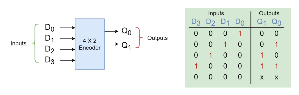
The output lines (Q0 & Q1) output a binary code to encode four input lines (D0, D1, D2, & D3). When D0 is “HIGH” then both outputs are “LOW”, similarly, a “HIGH” state of D1 input enables only Q0 to “HIGH”, and other inputs are encoded, accordingly. In an ordinary encoder, there is only one input with a logically “HIGH” state and can produce the wrong output when it has more than one input with a “HIGH” state. For example, when both D1 and D2 are “HIGH” then it would produce an output of “11” which belongs to the input address of D3 which is completely wrong.
The simplest way to overcome such a problem is to prioritize the inputs and when there is more than one input with a “HIGH” state then produce output code corresponding to the input with the highest designated priority only. So, the encoder which prioritizes the binary inputs to produce an equivalent binary code is called a Priority Encoder or P-encoder.
Parity Encoder
The Priority Encoder considers the priority assigned to each input and outputs the binary code at its outputs, accordingly. The output binary code of the input with the highest priority will be produced while all other inputs with lower priority will be ignored. So, by knowing the priority of each input, one can easily designate the address of the currently active input. The Priority Encoder comes in a variety of commercial packages depending on the number of inputs and, most commonly, used is an 8 to 3 Bit Priority Encoder which encodes eight (8) input lines to three (3) bit binary code considering priority.
The 8-to-3 Bit Priority Encoder
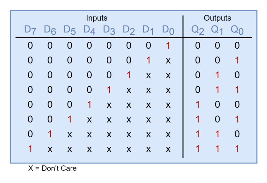
In the following figure, an 8-to-3 Priority Encoder has been shown along with its truth table. The 8-to-3 Bit P-encoders are available in commercial IC packages and 74LS148 is a TTL family 8-to-3 Bit Priority Encoder. The Priority Encoder typically sets the priority of its inputs depending on their ascending order. Considering eight (8) inputs from D0 to D7, the D0 input will have the least priority compared to other inputs and, on the other hand, the D7 will enjoy the highest priority. For example, if inputs D2 and D5 are active, simultaneously, then the input D5 will be given priority over D2 because of its higher order.
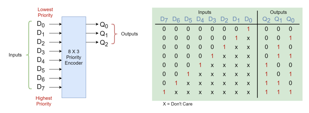
The truth table below shows a number of input conditions as “don’t care” and are labeled as “X”. This means that the output is not affected by any condition of either “0” or “1” at these “X” values. From the truth table, it is also observed that “don’t care” conditions enable the accounting of priority function at each of these input conditions.
The above truth table gives the following algebraic equations for the outputs of the 8-to-3 Bit Priority Encoder and the equations are simplified further to obtain reduced equations.
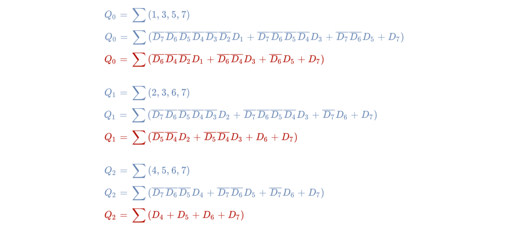
The Output Expressions of the 8-to-3 Bit Priority Encoder
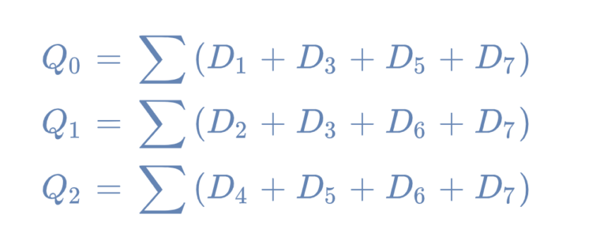
The reduced expressions of the parity encoder are further simplified by ignoring the “don’t care” or zero input conditions.
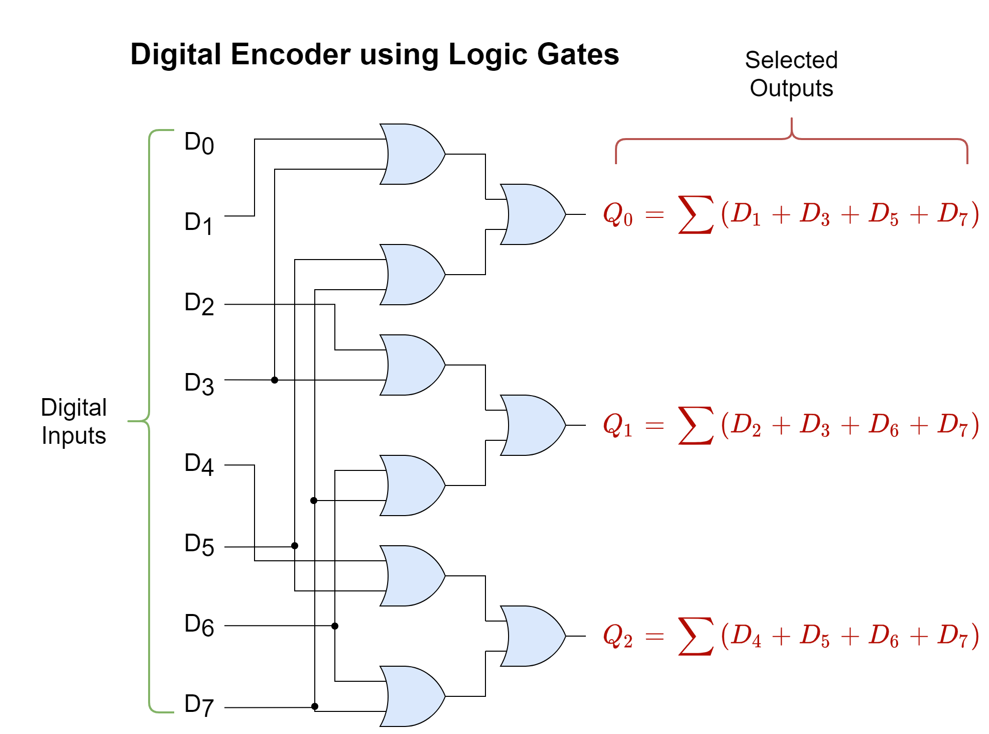
The Logic Diagram of 8-to-3 Bit Priority Encoder
From the above-simplified expressions, following the 8-to-3 Bit Priority Encoder can be constructed as shown below:
Applications of Digital Encoders
Digital encoders have a number of applications in digital circuits where a large number of conditions are encoded in smaller data bit sets. The major applications of digital encoders are described below:
Interrupt Requests
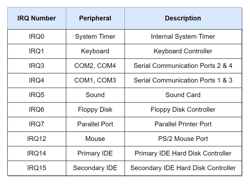
In digital systems, the Priority Encoders are used in connecting different peripherals or services to a microprocessor through interrupt requests. The multiple peripherals or I/O devices such as a keyboard, mouse, printer, scanner, or disk drive are each allocated with a priority level for an interrupt request. The microprocessor on interrupt request checks the interrupting devices and connects with the one having the highest priority and, using this way of communication, the microprocessor knows to which device it is communicating and sets the protocol, accordingly. Using the Interrupt Requests not only alerts the microprocessor or microcontroller that a device wants to communicate but also ensures that the devices are served in order according to their priority levels.
Rotary/ Position Encoder
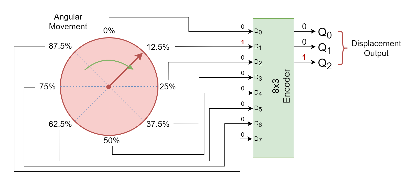
The Rotary or Position Encoders are frequently used in rotating or mechanical parts to determine the position of a rotating object. The most common applications include robots, rotating knobs, navigation systems, electric gates, etc. The rotational movement is divided into a number of segments or positions which gives the proportion or percentage of total displacement or rotation. Each segment or position drives the input lines of an encoder which produces a binary code of that specific position and is processed in the microprocessor, accordingly. The following figure shows a rotating knob that is divided into eight (8) segments and each segment is given a total percentage of rotation covered. The segments can be indicating to any specific information and can be driven through a sensor such as a compass or motor.
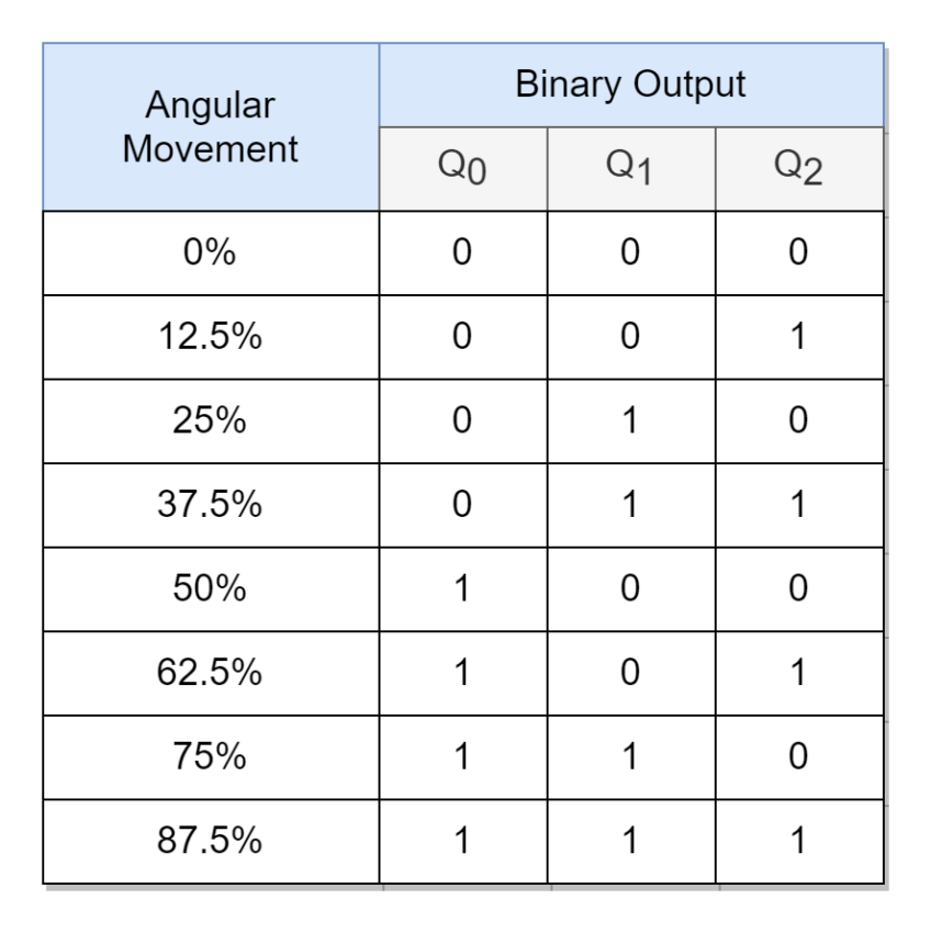
The following table shows the expected output binary code of the above rotary encoder.
Keyboard Encoder
The QWERTY keyboard typically uses 104 keys comprising of alphabets, numbers, special characters, etc., and is not feasible to have a dedicated data channel wired for each specific key. Instead, a Priority encoder is utilized to reduce the number of data wires at the output and the 104 keys of a keyboard are converted into American Standard Code for Information Interchange (ASCII). Each ASCII encoded data comprises of 7-bits which can hold information of 27 = 128 signals or keys. So, whenever a key is pressed on the keyboard, an “ACTIVE” or “HIGH” signal of that key is sent using one of its designated spaces from 0 to 127, and from this computer recognizes which specific key has been pressed on the keyboard.
Conclusion
- The Encoder is a combinational logic circuit that produces a specific binary or BCD code at its outputs in response to the active input(s). The Encoder converts 2n inputs to an n-bit specific code and, thus, can help in the reduction of signals for the transfer of information using the Encoder–Decoder combination.
- The Binary and Priority Encoders are the most commonly used Encoder types. The Binary Encoder is the simplest form of Encoder and is constructed using OR, or AND gates. However, it is prone to producing the wrong output when more than one active input is encountered.
- The Priority Encoder considers the designated priority of each input line when producing output code and, as such, overcomes the constraint encountered during multiple active inputs of a standard Binary Encoder.
- The Priority Encoder outputs binary encoded data of the inputs with the highest priority when there are multiple active inputs and ignores the rest of the active inputs.
- The Priority Encoders are used widely in digital systems where multiple input and output interfaces are utilized for information transfer. For example, they are used in Interrupt Handlers to process and distinguish between high and low-priority interrupt requests. In Rotary or Positional Encoders, a specific binary code is assigned to determine the rotational or linear movement by designating different portions. Also, Keyboard used an encoder to reduce the number of data wires required for the transfer of data to a computer.