Arduino released a cloud platform, Arduino Cloud, that would enable developers and hobbyists to build smart connected projects based on a wide range of electronic hardware products, such as Arduino, ESP32, and even ESP8266.
The company understands the entry barriers to using a cloud platform to develop next-gen smart IoT applications that would require the user to have a piece of comprehensive knowledge of the terminology and the environment. But with the aim of bringing IoT to all, Arduino carefully designed the cloud platform to provide a more user-friendly and intuitive experience.
Arduino knows that getting started with such platforms is always a big task for developers. But with a well-documented platform that would enable users to leverage development and firmware deployment over the air, Arduino wanted people to use phone devices to control their edge platform.
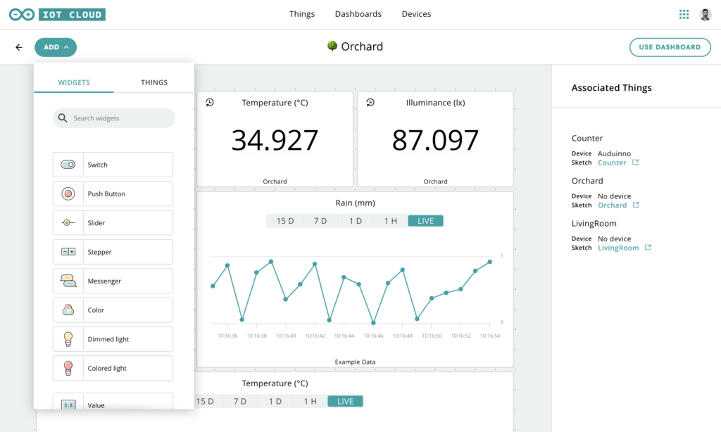
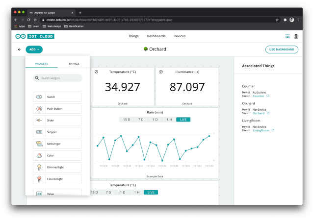
Now, Arduino has introduced a feature called phone devices with the goal to provide users with a tool that would allow them to have a quick out-of-the-box experience with the IoT cloud platform without the need of using a cloud-compatible board.
To use the new feature, Arduino requests its user to install the Arduino IoT Remote Application which is available for both Android and iOS. The user is able to see several sensors in your phone such as an accelerometer, GPS, microphone, compass, and even barometer. Through this, a dashboard is automatically created so that all these variables can be monitored.
Using these features, the company provides an easy way for newbies to understand the platform without actually owning a cloud-compatible device. But the Thing 2 Thing communication enables makers to want to use their phone sensors to activate several actions on their other things to build advanced use cases.
Arduino has provided detailed documentation on how to get started with the Arduino IoT Remote application. There are enough resources available on the Arduino Cloud website for a new developer and student community. For more information on the new product feature– phone device, head to the official website.
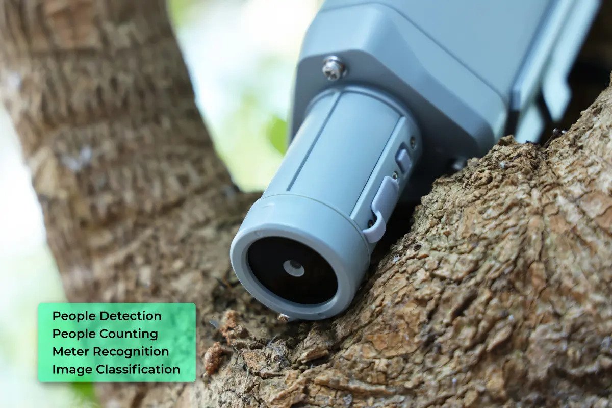
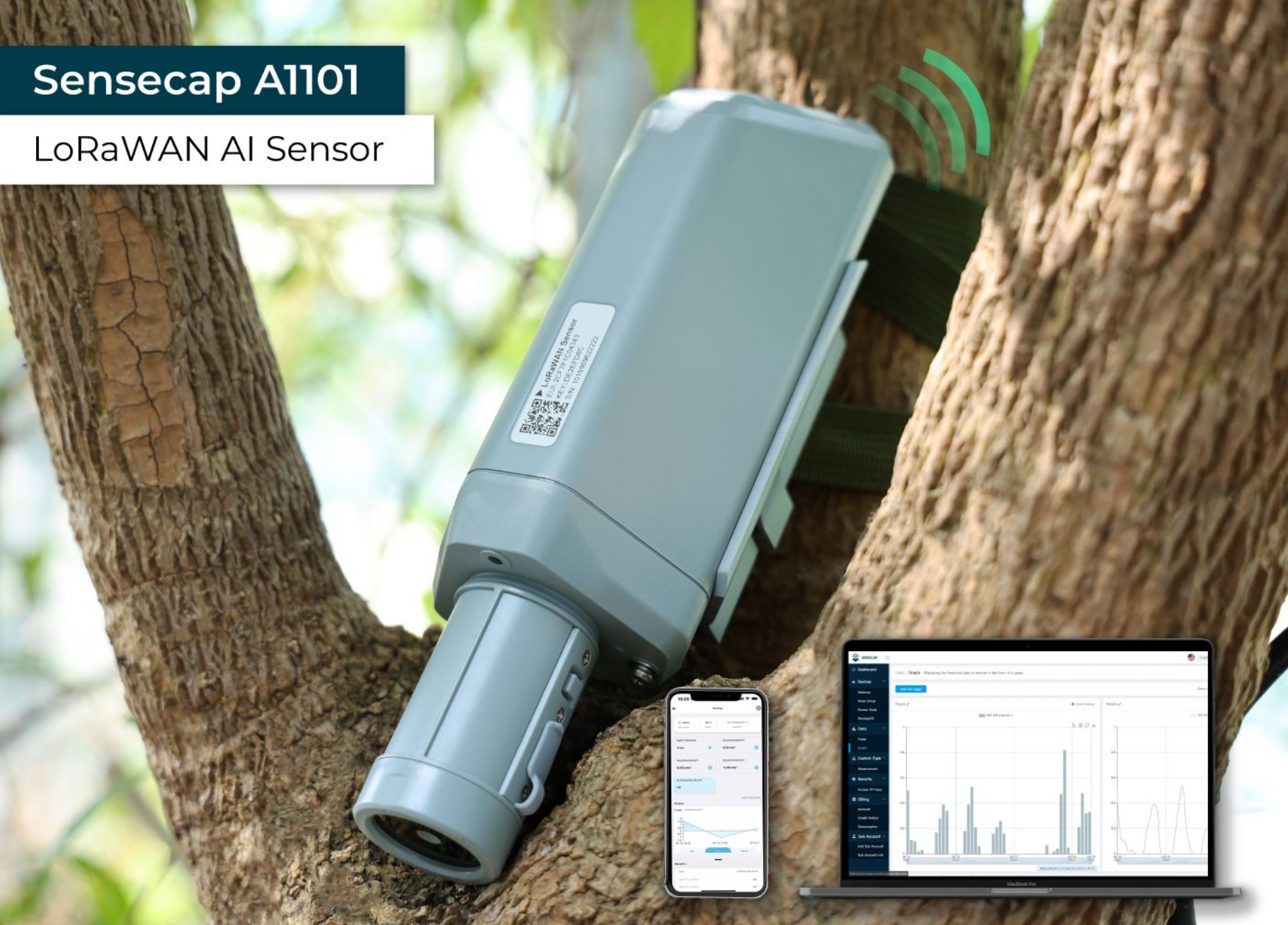
A Chinese manufacturer and designer of electronic hardware devices, Seeed Studio has unveiled a LoRaWAN-capable AI sensor that opens the door to leverage tinyML edge AI smart imaging applications– SenseCAP A1101. As a vision AI sensor, the hardware device is an image recognition solution designed for engineers that want to deploy edge computing and vision recognition applications at a low cost on a reliable hardware platform.
As mentioned earlier, the Seeed Studio SenseCAP A1101 hardware sensor comes with support for the LoRaWAN network for specific AI applications that demands to be deployed and scaled at distributed edge locations. At the heart of the SenseCAP A1101 is the low-power and powerful Himax camera capable of a maximum camera frame rate of 640×480 pixels at 60 frames per second.
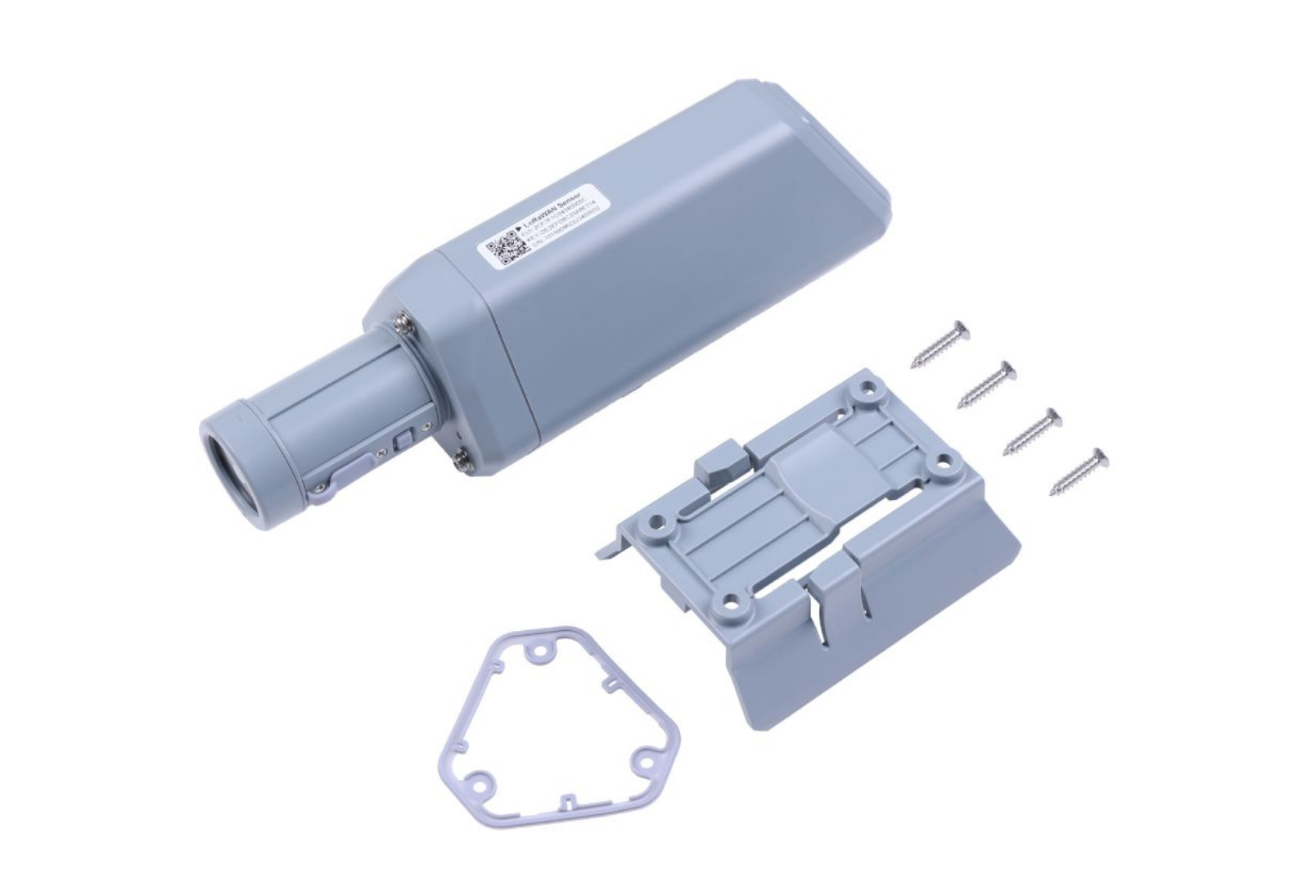
For wireless communication and long-range transmission, the SenseCAP A1101 has a Wio-E5 LoRaWAN module with a 2.3uWh speed mode power computation. Inside the Wio-E5 LoRaWAN module is the system-level package chip STM32WLE5JC featuring an Arm Cortex-M4 processor core and a long-range SX126X module.
To maintain the security standards, the hardware is capable of local image inferencing and transfers the result data to the cloud. With SenseCAP Mate applications and the SenseCAP cloud, the user can easily visualize the data while also managing it with other third-party tools.
The ideal camera setup for image collection depends on the pixel camera. For a 30-megapixel camera, the company suggests collecting images within 1m to 5m to get the ideal image effect. Also, the camera should be straight towards the object with sufficient illumination and avoid large movement and vibration when collecting images.
The AI capabilities of SenseCAP A1101 make it a good option for vision applications. The AI results depend on various factors, such as the quality of the image, the accuracy of the annotation, the way to generate the dataset, the model training process, and the algorithm used.
Seeed Studio SenseCAP A1101 is different from the company’s grove vision AI module as the newly launched SenseCAP A1101 is an industry-grade device with an IP66 rating. Users can benefit from the SenseCAP sensor platform by adding the SenseCAP A1101 to the SenseCAP Mate application and dashboard and deploying the application once the model training is completed.
If you are interested in understanding SenseCAP A1101 in detail, look at the official product page, where it is priced at $79.00 USD. Unfortunately, the product is currently out of stock, but you can sign up to get notified.
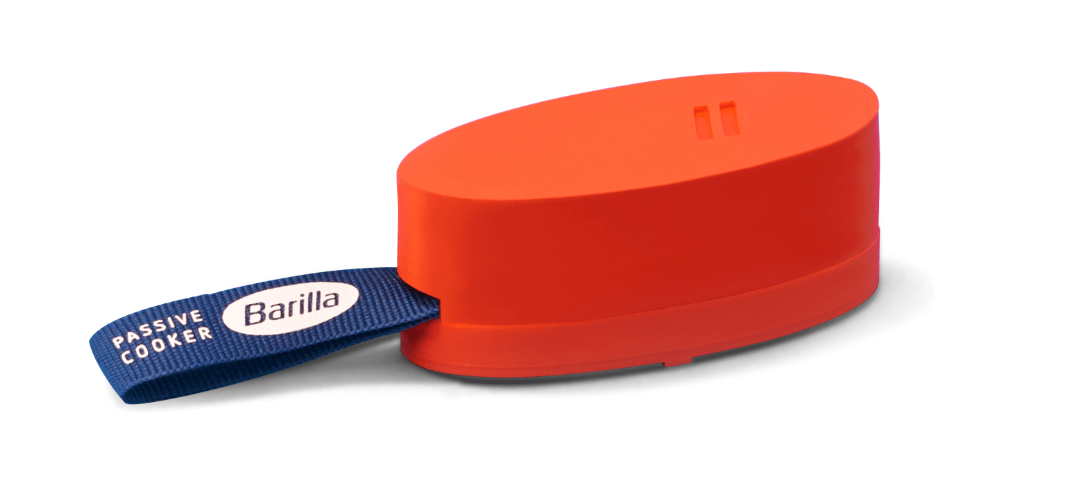
Arduino has written a blog post on Barilla using an Arduino Nano 33 BLE board to provide an open-source project for the passive cooking of pasta– makes a remarkable positive impact on the environment by reducing CO2 emissions by up to 80 percent, as claimed. As the blog post says,
“Italian grandmothers might cringe at the idea, but Barilla’s clear step-by-step guide,”
aims to bring a significant shift in the way Italians cook pasta, spaghetti, penne, and tagliatelle.
Barilla has provided detailed instructions on building your own passive cooker smart timer device, which equips a temperature sensor and an Arduino Nano 33 BLE board. The Arduino board is programmed using the Arduino IDE 2.0 and fitted inside a 3D-printed biodegradable casing. The smart device is also connected to a free mobile application to let the user know when to pour the pasta into boiling water and when to turn off the stove– a step towards saving energy.
“We wanted to make this project open source so everyone can make their copy and even improve it if they want to,” Barilla’s website states. “That’s Italian for “Hey, Arduino community! Let’s start cooking.”
Video
Arduino Nano 33 BLE board follows the same design as the Arduino Nano board, but features a more powerful processor– the nRF52840 from Nordic Semiconductors with a 32-bit Arm Cortex-M4 CPU clocked up to a frequency of 64MHz. As primarily designed for wearable devices, Barilla has selected the Arduino Nano 33 BLE board for its smart passive cooker in need of short-distance wireless communication.
Inside the open-source downloadable files, the company has provided 3D object design files for the Barilla thermometer bottom, Nano base, and top, along with Magnet insert, and ribbon holding insert. Other files include the most important Arduino program file which can be edited according to the customer’s requirement and add more capabilities to the hardware design. Due to its open-source nature, Barilla wants to provide a starting step for designers and hobbyists to come up with a more powerful and interesting smart cooking device.
For more information on the smart passive cooker, head to the official product page.
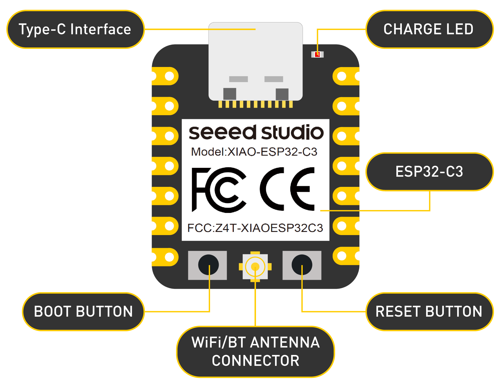
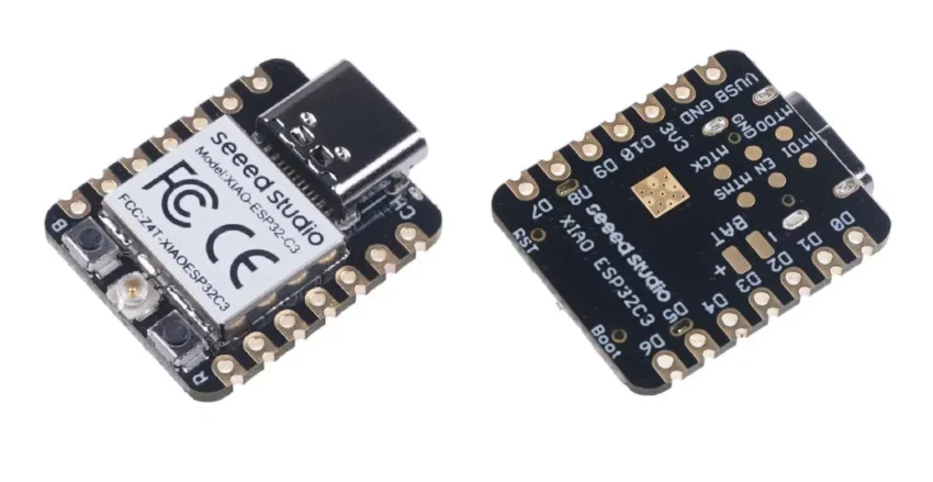
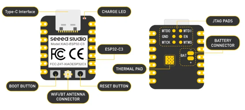
Seeed Studio XIAO series boards are smaller and fit into the thumb! Such a tiny structure helps in product making and innovating products that demand the overall product size to be small. The XIAO ESP32C3 from the Seeed Studio supports Wi-Fi and BLE wireless connections. It is based on the new RISC-V architecture, which makes it an ideal board for Internet of Things applications.
The board has an inbuilt battery charge chip with an integrated circuit. This feature enhances the product’s ability to be carried anywhere for battery-powered applications. The board is also designed to be surface mounted on a PCB carrying a compatible footprint. It has 11 digital IOs for PWM applications and 4 analog IOs for ADC applications. As with the other commonly available boards, it has UART, I2C, and SPI functionalities. If you are familiar with Arduino programming, working with ESP32C3 is a cakewalk! The external antenna included with this board is very useful for wireless applications requiring larger signal strength.
Features:
It consists of an ESP32-C3 SoC with RISC-V single-core 32-bit chip processor. It is coupled with a four-stage pipeline up to 160 MHz frequency range.
Operating range of 3.3V@200mA with a charging current of 50-100mA.
Wi-Fi power consumption is as low as less than 4 mA during the light-sleep model, while the BLE power consumption is as low as less than 10mA.
The Deep Sleep Model consumes only 44uA of current.
The on-chip memory has 400KB of SRAM / 4MB flash memory.
The wireless features include a complete 2.4GHz Wi-Fi subsystem and Bluetooth 5.0.
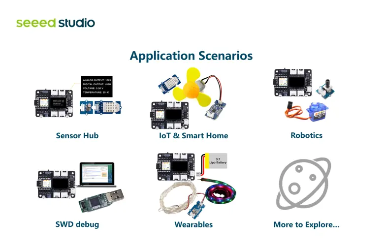
Applications
The XIAO ESP32C3 board finds a lot of real-time applications. This includes the Internet of Things, where many such boards can be interconnected to form a network. This network is also low-powered, thanks to the feature of the board. The board also has such a small factor that it is ideal for making wearable devices. Health monitoring is another area of application for recording various health-related parameters. It is suitable for rapid prototyping because it is compatible with breadboard and soldering.
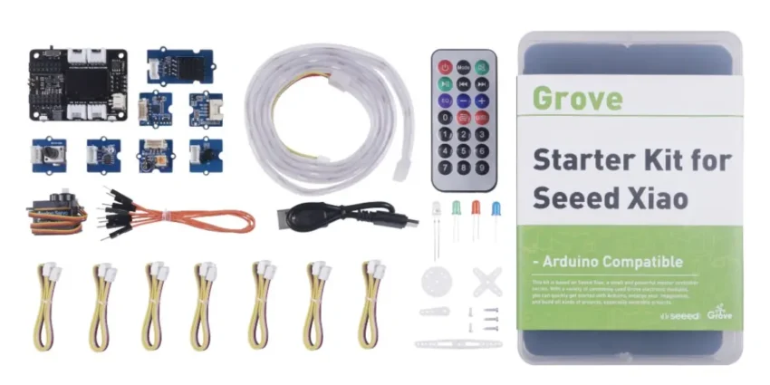
Getting Started kit
The Grove Starter Kit from the Seeed Studio is an ideal starting point for all beginners and those starting new with XIAO boards. The kit also includes free and detailed courses to let you learn easily. Thus, the learning curve is not as steep as those with other new embedded platforms.
The starter kit offers a fundamental understanding of the use of simpler projects. These simple projects can be further developed to make complex and real-time projects. You do not need special programming skills or electronics knowledge with the starter kit.
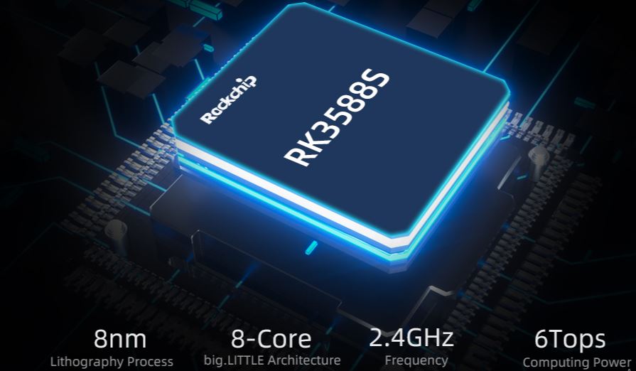
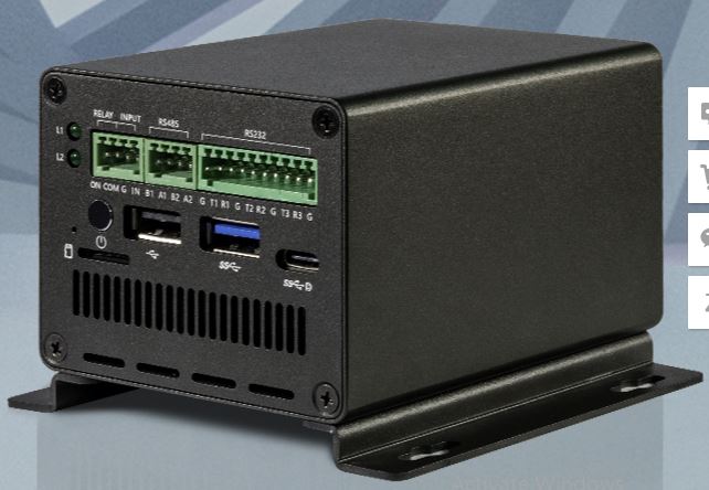
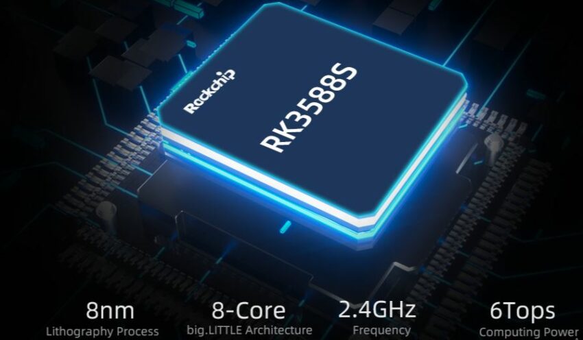
Firefly’s EC-R3588SPC is a new industrial mini PC optimized for advanced applications. The EC-R3588SPC mini PC is powered by a new generation of high-end processors from Rockchip – the RK3588S AIoT SoC – equipped with an 8-core Cortex-A76/A55 CPU, an ARM Mali-G610 MP4 quad-core GPU and a built-in AI accelerator NPU providing 6 TOPS.
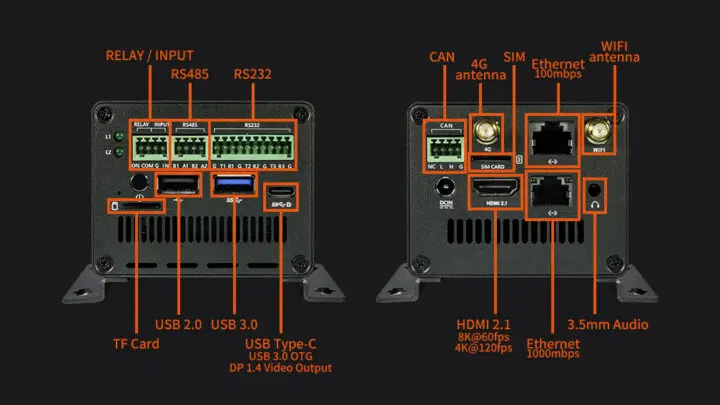
The mini PC is further equipped with up to 32GB RAM and 128GB eMMC flash, M.2 NVMe or SATA storage, a strong video encoding and decoding capability, and numerous interfaces used for industrial purposes such as RS485 and RS233, CAN Bus, Relay, and digital input. Gigabit Ethernet, fast Ethernet, WiFi 4, Bluetooth 5.0, and 4G LTE are also available for strong network connectivity. Others include 8K-capable HDMI 2.1 and DP1.4 video outputs, USB ports, and a 3.5mm audio jack.
The EC-R3588SPC mini PC should be well suited for intelligent retail and smart industrial applications, edge computing, Artificial Intelligence, VR/AR, smart home, and smart security.
Specifications:
System-on-chip
Rockchip RK3588S octa-core processor with:
CPU: 4x Cortex-A76 cores running at up to 2.4 GHz and 4x Cortex-A55 cores running at up to 1.8 GHz
GPU: Arm Mali-G610 MP4 quad-core processor with OpenGL ES3.2/OpenCL 2.2/Vulkan1.1 support
VPU: 8K@60fps H.265/VP9/AVS2 video decoder, 4K@60fps AV1 decoder, 8K@30fps H.265/H.264 video encoder
AI Accelerator: 6 TOPS NPU
Super Large System Memory & Storage
4GB, 8GB, 16GB or 32GB LPDDR4/LPDDR4x/LPDDR5
16GB, 32GB, 64GB, or 128GB eMMC flash
1x MicroSD card port
Default M.2 socket for M.2 2242 SATA SSD or NVMe (PCIe 2.0) SSD
Multichannel Video & Audio Outputs:
HDMI 2.1 port up to 8k@60 or 4k@120
DisplayPort 1.4 up to 8k@30 via USB-C port
2x independent displays
3.5mm audio jack
Digital audio output via HDMI and DP ports
Strong Network Communication:
1x GbE RJ45 port
Dual-band WiFi 5.0 and Bluetooth 4.2 BLE with external antenna
Optional 4G LTE module with external antenna
Power Supply
12V DC input via DC jack
Dimensions
96.6 mm x 72 mm x 64 mm
Weight
450 grams
Temperature Range
Operating: -20°C to 60°C
Storage: -20°C to 70°C
Humidity
40% to 70%
Variety of Interfaces
M.2 (PCIe 2.0) socket for NVMe SSD
Relay/digital input
RS485
RS232
CAN Bus
L1/L2 LEDs
1x USB 3.0 Type-A port
1x USB 2.0 Type-A port
1x USB 3.0 OTG Type-C port
Various Operating System Support
Android 12.0 and Ubuntu Desktop/Server
Relevant resources for customization such as tutorials, development documents, and examples are also provided for further customization.
The product is available for purchase on AliExpress for $330 for the 4GB RAM/32GB flash model, or $427 for 8GB RAM/64GB flash model. Other useful details on the EC-RK3588SPC can be found on the official product page.
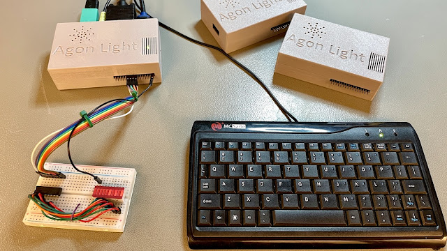
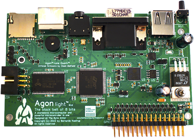
Agon Light is a compact low-cost board that is both a microcomputer and an instant-on, BASIC-programmed microcontroller. The fully open-hardware open-source board sits between being a microcontroller development board like an Arduino and a conventional single-board computer like a Raspberry Pi. It happens to be a very fast, cheap, and the most hackable 8-bit microcomputer ever.
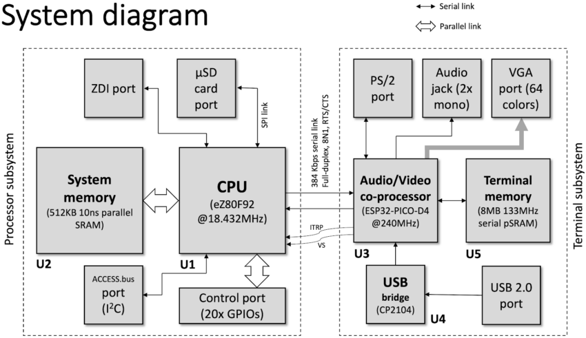
Built with state-of-the-art 21st-century technology, the board design aims at the best trade-off across performance, cost and flexibility. Agon Light comes with an 8-bit eZ80F92 3-stage pipelined CPU running at a blazing clock speed of 18.432MHz and featuring a 24-bit address bus that can directly address up to 16MB of memory and I/O. The board also has an audio-video coprocessor in the form of Espressif ESP32-PICO-D4 system-on-a-chip which runs at 240 MHz, 512KB of SRAM system memory, and 8MB of SRAM audio/video memory.
Other features which make the board fit as both a microcomputer and a microcontroller include a microSD card, VGA video output, and GPIOs.
“As a microcomputer,” the Byte Attic blog explains, “Agon is a standalone device that requires no host PC: it puts out its own video (VGA), audio (2 identical mono channels), accepts a PS/2 keyboard and has its own mass-storage in the form of a µSD card. As a microcontroller, it has a control port featuring SPI, I2C, twenty or more distinct GPIO lines (including lines for serial communication), a system clock output, as well as power (3.3V and 5V) and ground rails.”
You can do all your programming right on it without needing a separate computer; writing and debugging your code in BASIC.
Specifications Include:
CPU: eZ80F92 running at 18.432 MHz; 24-bit address bus
ESP32-PICO-D4 VDP (Video Display Processor)
512KB of SRAM system memory
8MB of PSRAM audio/video memory
VGA output with 640 x 480 pixels resolution and 64 simultaneous colors
1x microSD card slot for storage
PS/2 Keyboard slot
20x GPIO, plus SPI, I2C, UART for serial communication
Input Power: 5V via either USB or GPIO port
Agon Light sets the pace with a large margin compared to the performance of other machines. It scores best in all popular microcontroller benchmarks including the Rugg/Feldman benchmark, Noel’s Retro Lab’s BASIC benchmark, and Matt Heffernan’s “Battle Royale” benchmark.
The board is also built for maximum flexibility. Its entire firmware suite can be programmed in Standard C with freely-available tools such as Arduino IDE and Zilog’s ZDS-II IDE.
“Instead of having to program kernel code in assembly to write to EPROM, you can simply write C code, compile it with free tools and upload your firmware into the eZ80’s and the ESP32’s embedded flash memories. You have full control not only of the basic functionality of Agon Light, but also of the look-and-feel the user experiences upon turning the machine on. You can brand it yourself and show your dream computer to your friends,”
the Byte Attic blog further explained.
The board can be used for a variety of things since it’s an 8-bit microcomputer that boots instantly into a BASIC programming interpreter. It is a bit like a vintage ZX Spectrum or Commodore 64 and can equally do almost everything you use those computers for.
Well, from the look of things, Agon Light might eventually have a “heavy” version as the maker of the board also plans to make a high-performance model with the newly released eZ80F91 processor system running at 48MHz and with 256KB of embedded flash, 16KB on-chip high-speed SRAM. The future model will also have 2MB of onboard SRAM, a mouse port, RTC, a speaker, and more GPIOs than the “Light” version.
Prices for Agon Light depend on whether you are ordering the fully assembled version with firmware, with/without a case, with/without a microSD card, or with a PCB only.
Those from the UK can visit here to see these various options with their prices while buyers from Australia, NZ, and Oceania can go here to place orders.
Other useful details on the Agon Light can be found on the official product page.
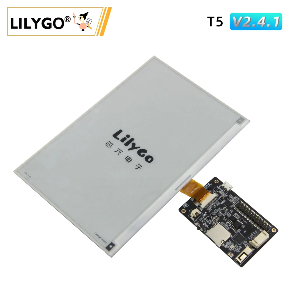
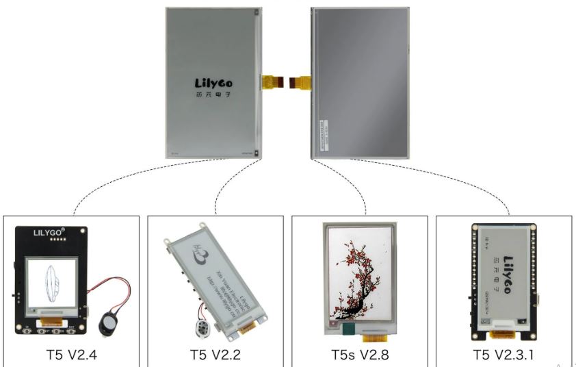
It used to have smaller sizes of e-paper displays connecting to LilyGO’s ESP32 boards. We saw that in the TTGO T5 which offers a choice of e-Paper displays from 1.54 inches to 2.3 inches, and the Mini e-paper Core with a really tiny 1.02-inch e-Paper display.
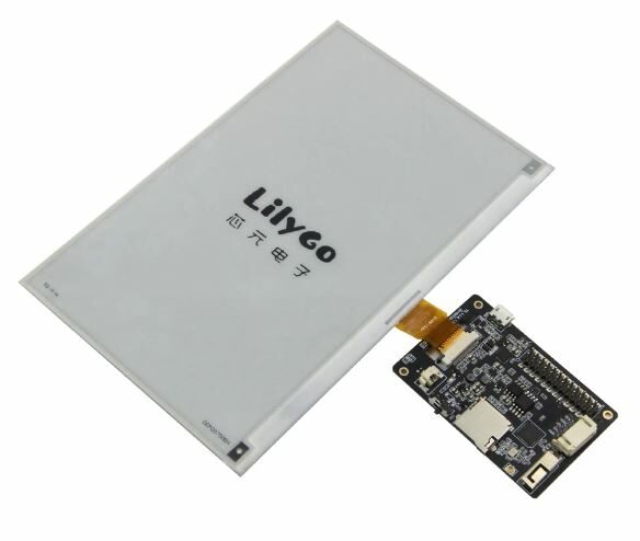
LilyGO is now offering up to a 7.5-inch screen display that works well with most of their T5 boards. So we can now have an ESP32 board connected with a 7.5-inch e-paper display.
LilyGO did not disclose much information on the 7.5-inch e-display but we were able to gather some facts.
The $52 7.5-inch e-paper weighs 44 grams and has a resolution of 800 x 480 pixels, a wide viewing angle and clear display, ultra-low power consumption, and communication via SPI interface. It is Arduino-programmable and backward compatible with the previous T5 E-paper solutions.
Features of the 7.5 inch e-paper display Include:
High contrast high reflectance
Ultra-wide viewing angle
No backlight displays the last content for a long time even when power is down
Consumes a minimal amount of power. Power is basically consumed only while refreshing
Comes with several development resources and examples for Arduino-esp32
Arduino programmable and backward compatible with previous T5 e-paper solutions.
The LilyGO 7.5-inch e-display is a cheaper alternative to the Inkplate wireless displays which are also based on the ESP32, but the latter has better resolutions, a front light, a battery charging circuit, a touch screen, and possibly higher refresh rates.
The 7.5-inch electronic ink screen supports T5 development motherboards with 1.54, 2.13, 2.6, 2.7, 2.9, or 3.7 inches displays, but it is not compatible with the T5-4.7-inch board. It is perfect for applications such as shelf labels and industrial instruments.
The 7.5 inch electronic paper display currently goes for $52, but if you are getting it with the T5 2.4.1 board, you will pay an additional $7, totaling $59.
You can check GitHub for guidelines on how to use the Arduino IDE along with the Adafruit GFX library to drive the e-paper display from the ESP32 microcontroller.
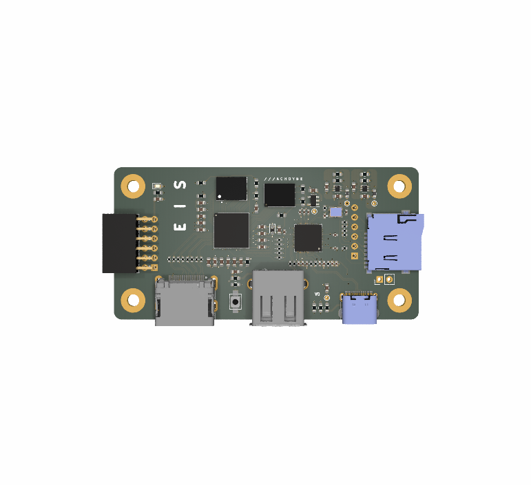
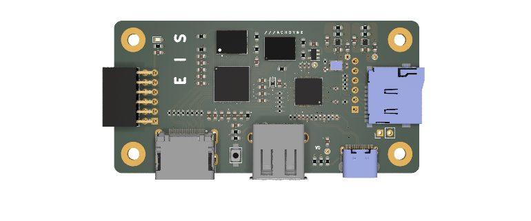
Machdyne is an American technology company focused on developing small general-purpose computers, modules, and tools optimized for timeless applications. The company recently unveiled a small FPGA-based board named Eis, which they have been working on for a while now and plan to make available to the public soon.
“Eis is an FPGA-based computer board designed for timeless applications,”
says the company.
Eis is powered by the Lattice ICE40HX4K FPGA. The Lattice ICE40HX4K FPGA is an ultra-low power, non-volatile FPGA fabricated on an advanced 40nm CMOS low power process and with flexible logic architecture, embedded and distributed memory, programmable low swing differential I/Os, up to 2 analog PLLs (Phased Locked Loops) and 7680 LUTs (Look-Up Tables).
The board also comes with the high-performance low-cost RP2040 MCU, Raspberry Pi’s debut microcontroller with large on-chip memory, a rich peripheral set augmented with a unique Programmable I/O subsystem, and a polished micropython port. There are also other features embedded inside the FPGA-based board including one Digilent Pmod compatible expansion port, one MMOD socket, one microSD card slot, and one DDMI port with support for DVI output over HDMI cable.
The board is actually smaller than a credit card, measuring 80 mm by 40 mm. It shares similar features with one of Machdyne’s other products named Riegel. “Eis is a slightly smaller reimagining of Riegel,” the company also said, comparing the two boards. One notable difference between the two, however, is that:
“Eis has a USB keyboard port and DVI over HDMI video output instead of PS/2 and VGA.”
Board Specifications for the Eis Computer Include:
Lattice ICE40HX4K FPGA
Logic Cells (LUT + Flip-Flop): 3520
RAM4K Memory Blocks: 20
RAM4K RAM bits: 80K
Phase-Locked Loops (PLLs): 2
Max Programmable I/O pins: 95
Max Differential Input Pairs: 12
High Current LED Drivers: 0
RP2040 microcontroller (dual 32-bit ARM Cortex M0+) with:
USB-C for power and programming
USB host port for keyboard
8Mbit QSPI NOR flash for firmware
32MB OSPI PSRAM
1MB NOR Flash
512MB of Static RAM
1x microSD card slot
1x MMOD slot
1x Digilent Pmod compatible port
1x Differential Data Multiple Interface port which supports DVI over HDMI video output
Dimensions: 80 mm x 40 mm (Smaller than a credit card)
Not many details were released about the board and there is no word yet on how much it will cost or when it is going to be available for purchase but the product page has other useful information including datasheets for the iCE40 family of FPGAs, the PSRAM, and the SRAM.
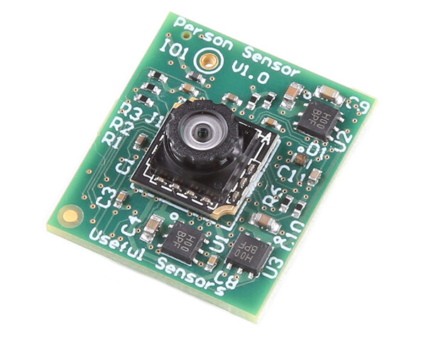
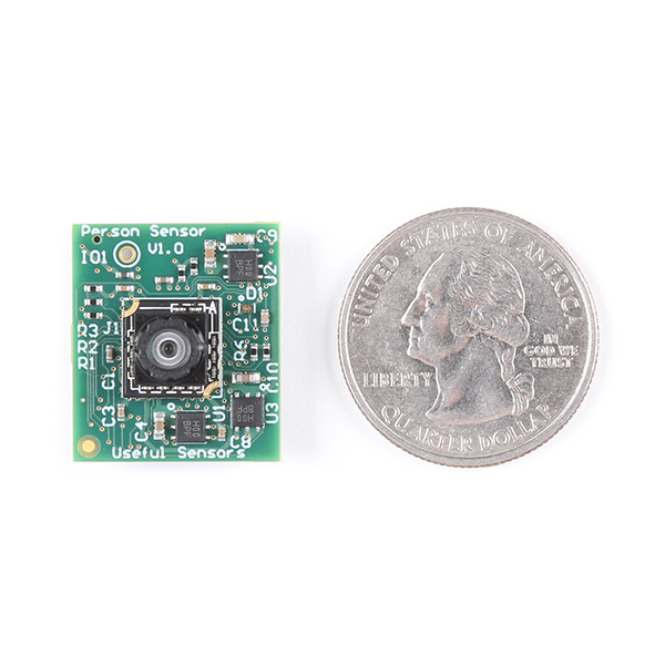
Useful Sensors has designed a small low-cost hardware module capable of detecting nearby faces and returning information about who they are, how many they are, and where they are with respect to the device.
This Person sensor makes use of a camera and a small microcontroller, with pre-programmed machine learning algorithms that can recognize people right out of the box so there is no need to build or train any model yourself. The information gathered is sent back over a simple Qwiic I2C interface.
The Person Sensor is quite easy to use so you do not need any special technical expertise for it, even as a new user. Just power it up and face the camera in the direction you are interested in. There’s a dedicated pin that is used to indicate if any person has been detected. Also, ensure the lens is placed the right way since the sensor uses a camera sensor internally. Describing how it should be, SparkFun says:
“you should be able to see the side of the board that has the sensor by spotting the small lens in the center. You will know you have it the right way up when the silkscreen writing “Useful Sensors Person Sensor V1.0” is at the correct orientation.”
The sensor module is also designed with privacy built-in, allowing only metadata derived from each available frame and not raw image data.
Specifications Include:
1x Pre-programmed microcontroller
1x Qwiic Connector for the I2C interface
110 degree Field of View for the Image sensor
Image scan rate (active with facial recognition): 5Hz
Image scan rate (without facial recognition): 7Hz
Low power consumption (150 milliwatts)
3.3V operating voltage
5 milliwatts LED power consumption
Up to 400k baud speed for I2C
Built-in privacy – module allows just metadata derived from each frame and not raw image data
The Person sensor can be used to build other smarter devices. Considering how simple, cheap, and power efficient it is, we expect to start seeing many projects built around it soon. But before then, you could just grab one to experiment with. You may want to use it to build applications that wake up when people approach, mute a microphone when nobody is present, automatically lock your screen when you step away from it or even minimize the current window you’re working on if someone is looking over your shoulder.
More details on the Person sensor are available on SparkFun’s blog or online store where the module sells for $10. You’ll also find some other useful details in the developer guide.
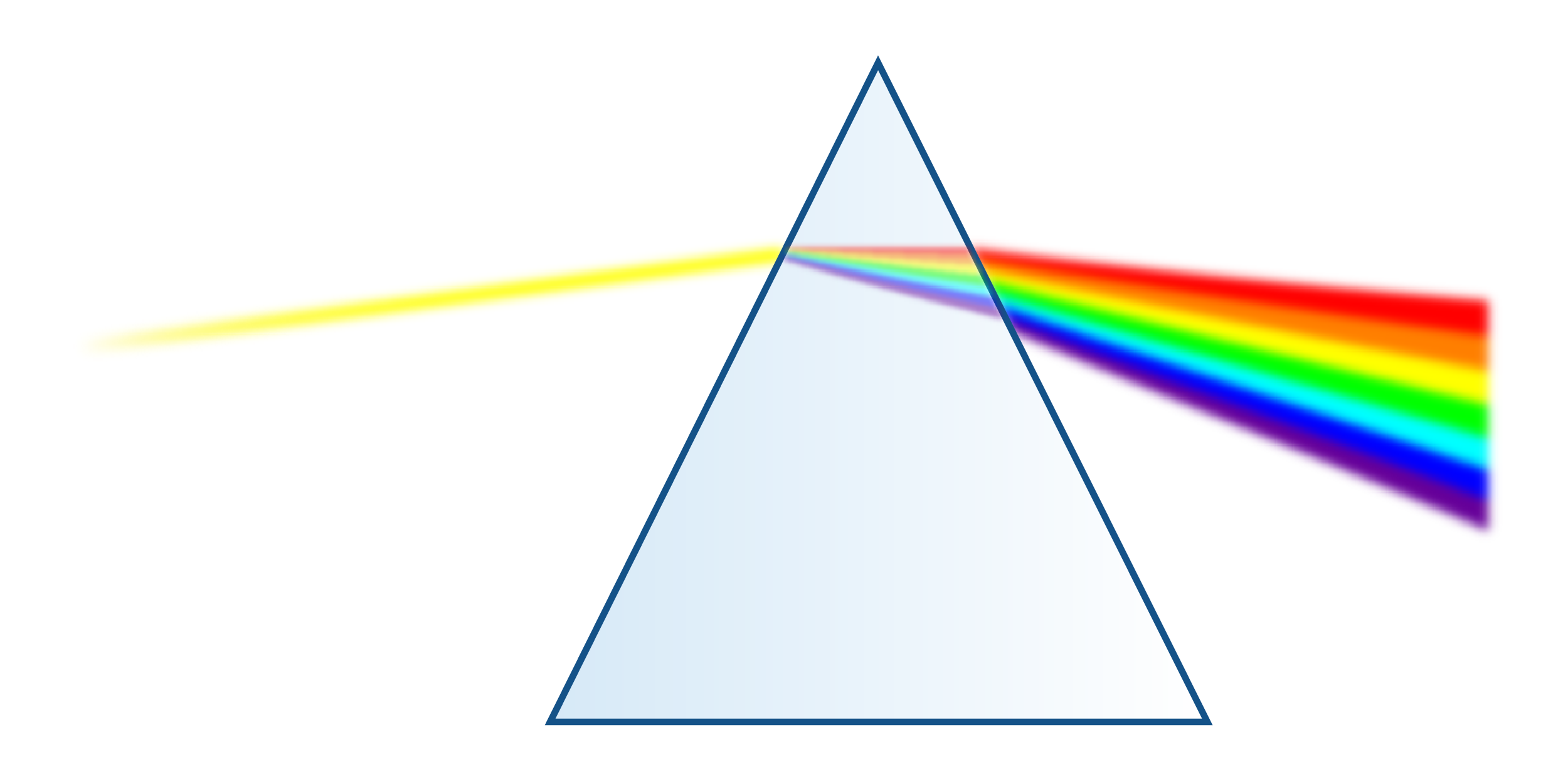
This subject was first assumed by Isaac Newton about 400 years ago. Newton showed that white light is composed of other colors. He called the color components of white light as “spectre”, from which we get the word spectrum. Figure 1 shows how a light beam is dispersed to some component colors i.e., waves with different frequencies from red (the lowest frequency of visible light) to violet (the highest frequency), after passing through a prism.
Figure 1: Dispersion of sunlight by a prism
Then, Jean Baptiste Joseph Fourier (1768-1830), a French mathematical physicist, discovered that any periodic waveform can be represented as a sum of an infinite number of weighted sinusoids, i.e., sine and cosine waves. Fourier’s theory states that any periodic function can be synthesized using these sinusoidal waves. Generally, using more sinusoidal waves produces a better result. This sinusoid summation concept is called the Fourier series. Fourier Series deal with functions that are periodic over a finite time interval. These arbitrary functions are assumed to repeat outside this interval.
The basic building blocks of Fourier analysis come from a set of harmonic sinusoids, called the basis set. This basis contains an infinite number of periodic sinusoids of different frequencies known as harmonics. Each individual wave is named an element of the basis.
The process of decomposing an arbitrary periodic signal into a set of basic waves is termed Analysis. We can re-create the periodic signal by putting together (adding) some waves from the basis set. This process is called Synthesis.
Square wave analysis in the time domain
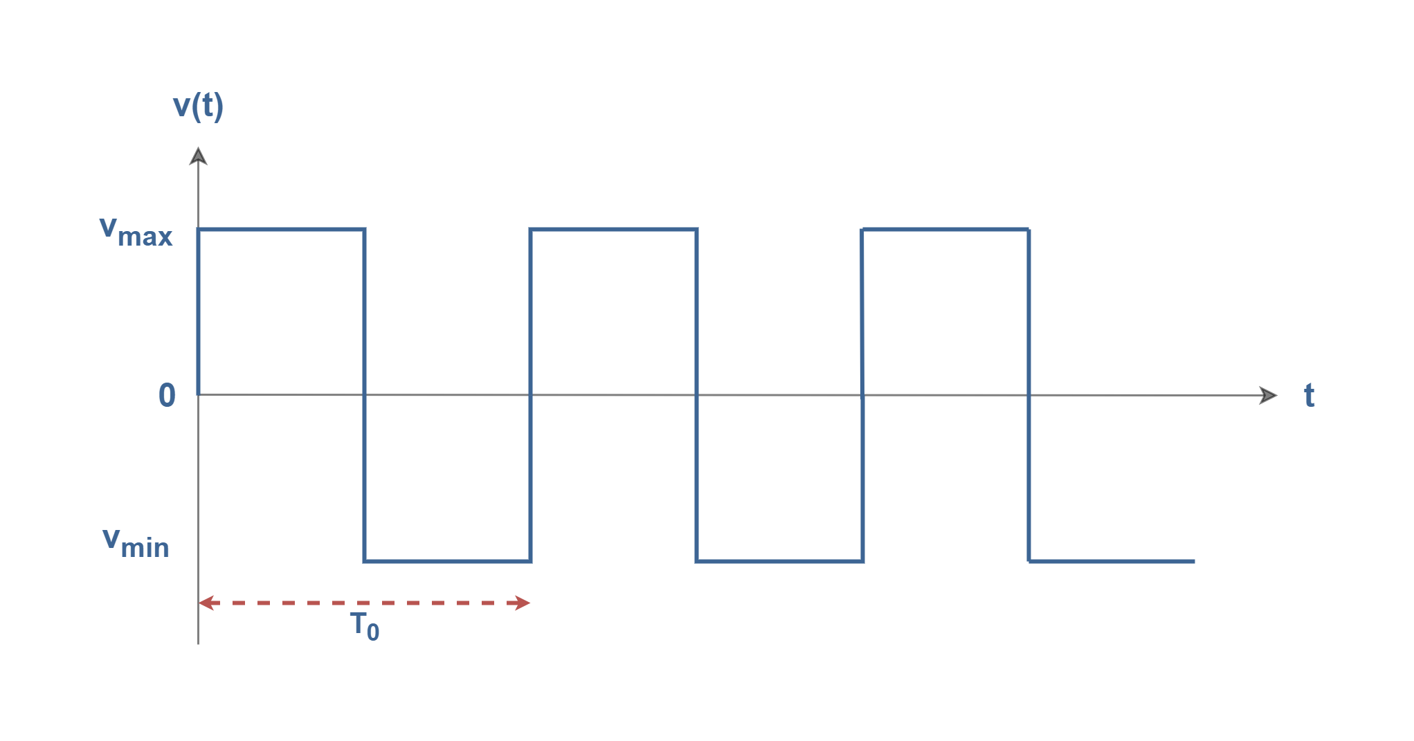
It is advantageous to examine the construction of a square wave as an example. The square waves are very useful in signal processing and data transmission. It is possible to create them by just adding a set of sinusoids. Figure 2 shows a pure square wave with a rectangular-shaped waveform in the time domain with a frequency of f0 (= 1/ T0) and with the maximum amplitude of Vmax.
Figure 2: A typical square wave
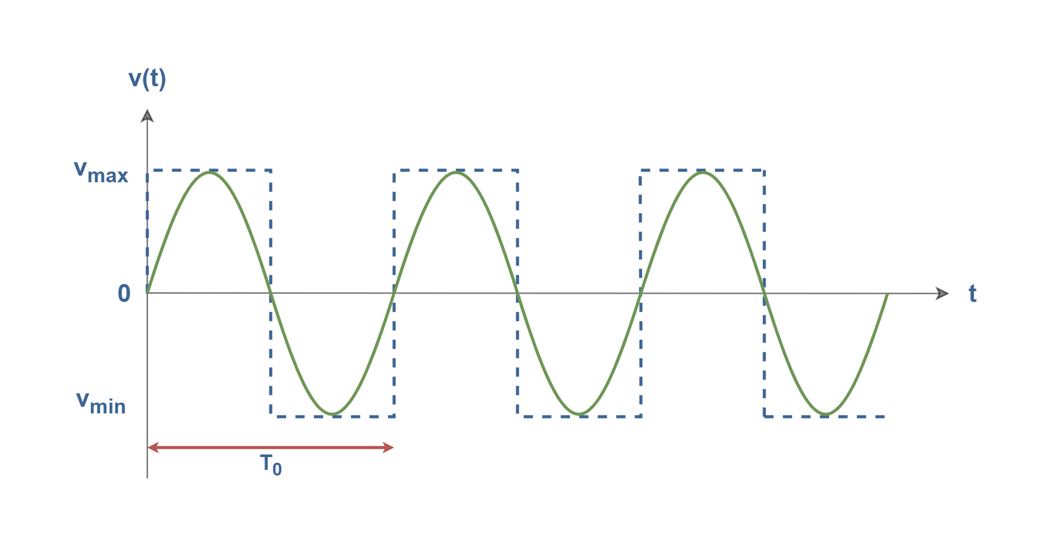
In Figures 3-1 to 3-5, we have created a square wave by adding together only a few harmonic sinusoids, i.e., the synthesis procedure. In Figures 3-1, we have only one sine wave with the fundamental frequency of f0 (= 1/ T0) and with the maximum amplitude of Vmax.
Figure 3-1: The fundamental wave (1st harmonic)
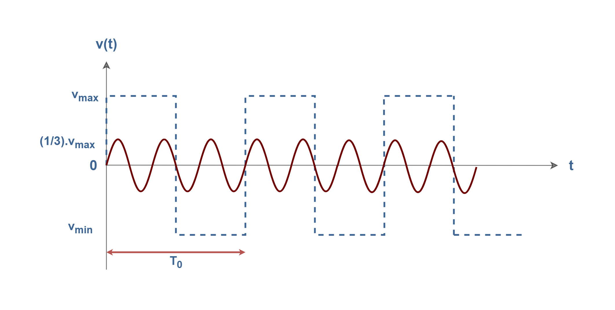
In Figures 3-2, we have the second sine wave with a frequency three times the fundamental (3f0) and with the maximum amplitude of one-third of the original signal (Vmax /3).
Figure 3-2: The 3rd harmonic wave
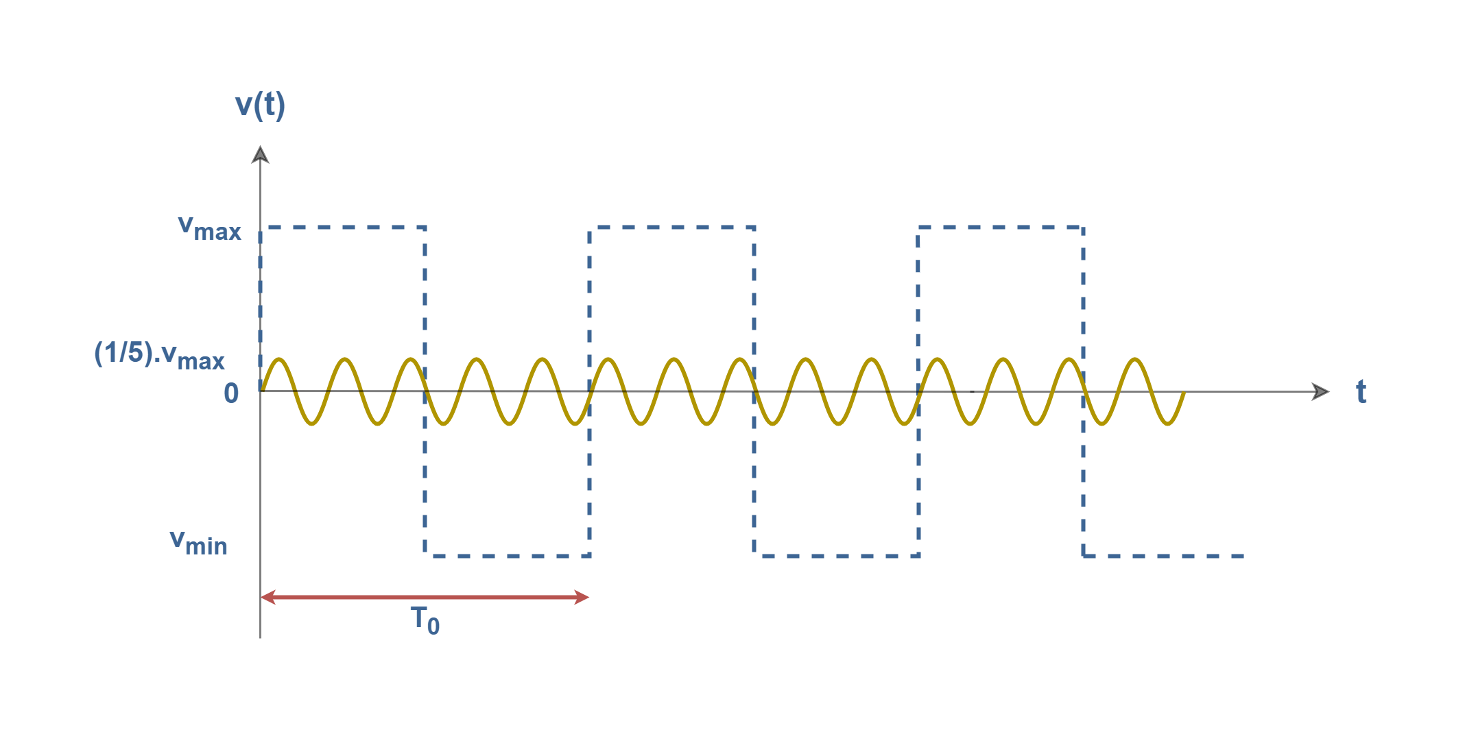
In Figures 3-3, there is the third sine wave with a frequency of five times the fundamental (5f0) and with the maximum amplitude of one-fifth of the original signal (Vmax /5).
Figure 3-3: The fifth harmonic wave
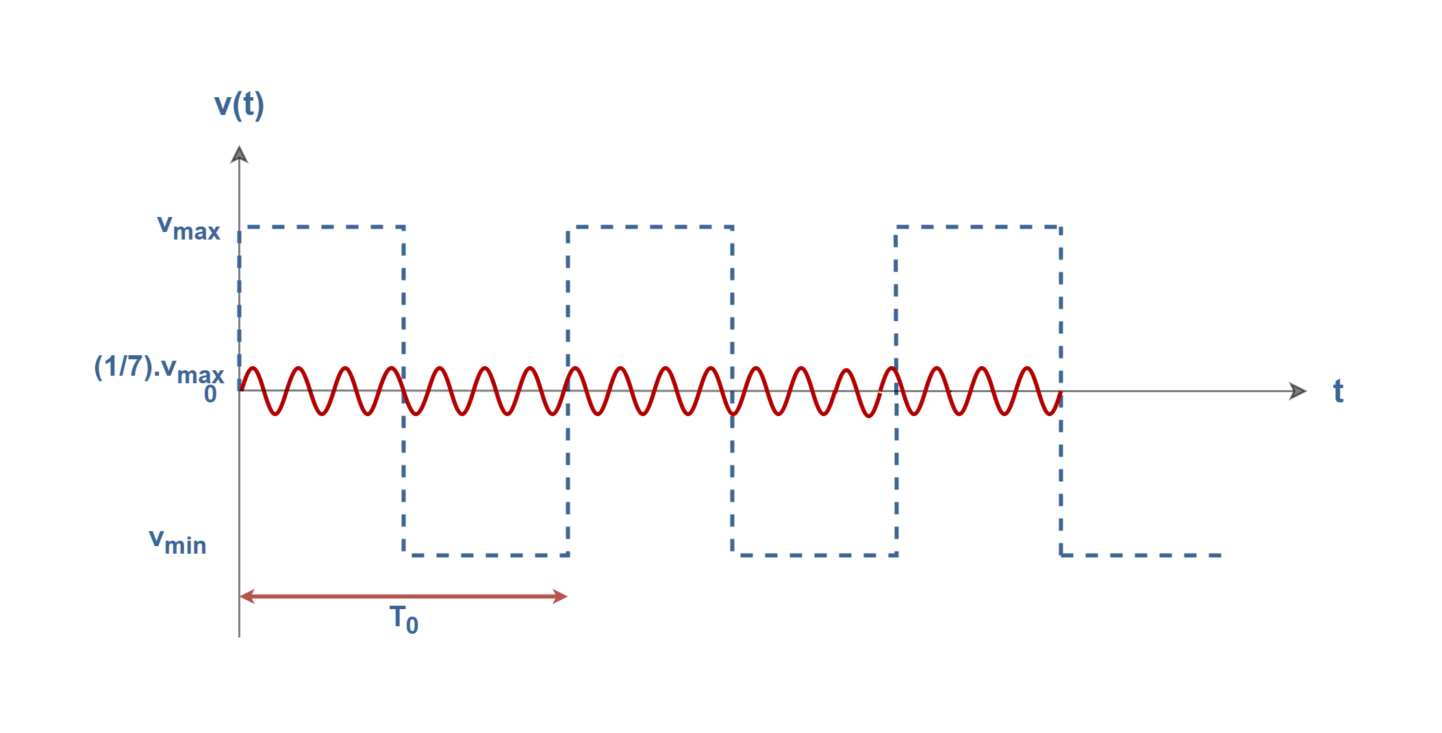
Figures 3-4 show the forth sine wave with a frequency of seven times the fundamental (7f0) and with the maximum amplitude of one-seventh of the original signal (Vmax /7).
Figure 3-4: The seventh harmonic wave
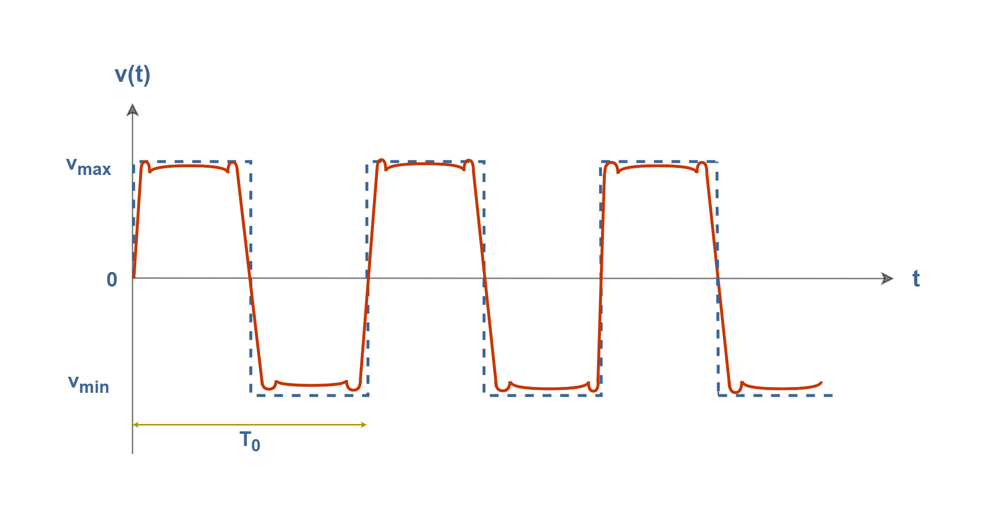
Finally, we add all of their amplitudes in each corresponding instance of time and the resultant waveform is shown in Figure 3-5.
Figure 3-5: The resultant waveform of the sum of the previous 4 sinusoidal waveforms
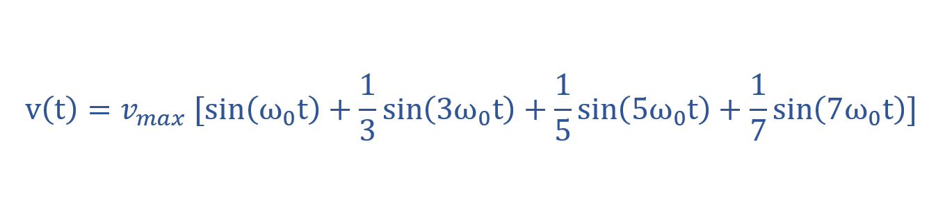
Hence, the steps that we took to make or synthesize a square wave by summing odd harmonics with different amplitudes can be explained in a simple mathematical model in Equation 1. This can be shown as a simple Fourier series.
Equation 1: A simple Fourier series for a square wave by 4 elements (harmonics)
Therefore, after analysis of the periodic signal into sinusoidal waves, the original time-domain signal is able to be reconstructed by adding together all the sinusoidal signals at every corresponding instance of time, i.e. the original signal is obtained from the superposition of component waves. This is the basic idea of the Fourier analysis method.
The more sinusoids we add to the summation, the better the wave looks, with the wiggles getting smaller. Hence, the Fourier series represents an estimate of the true representation, the accuracy of which depends on the number of terms used. Although, this form of harmonic representation may not result in a perfect reconstruction of the original signal.
Square-wave analysis in the Frequency domain
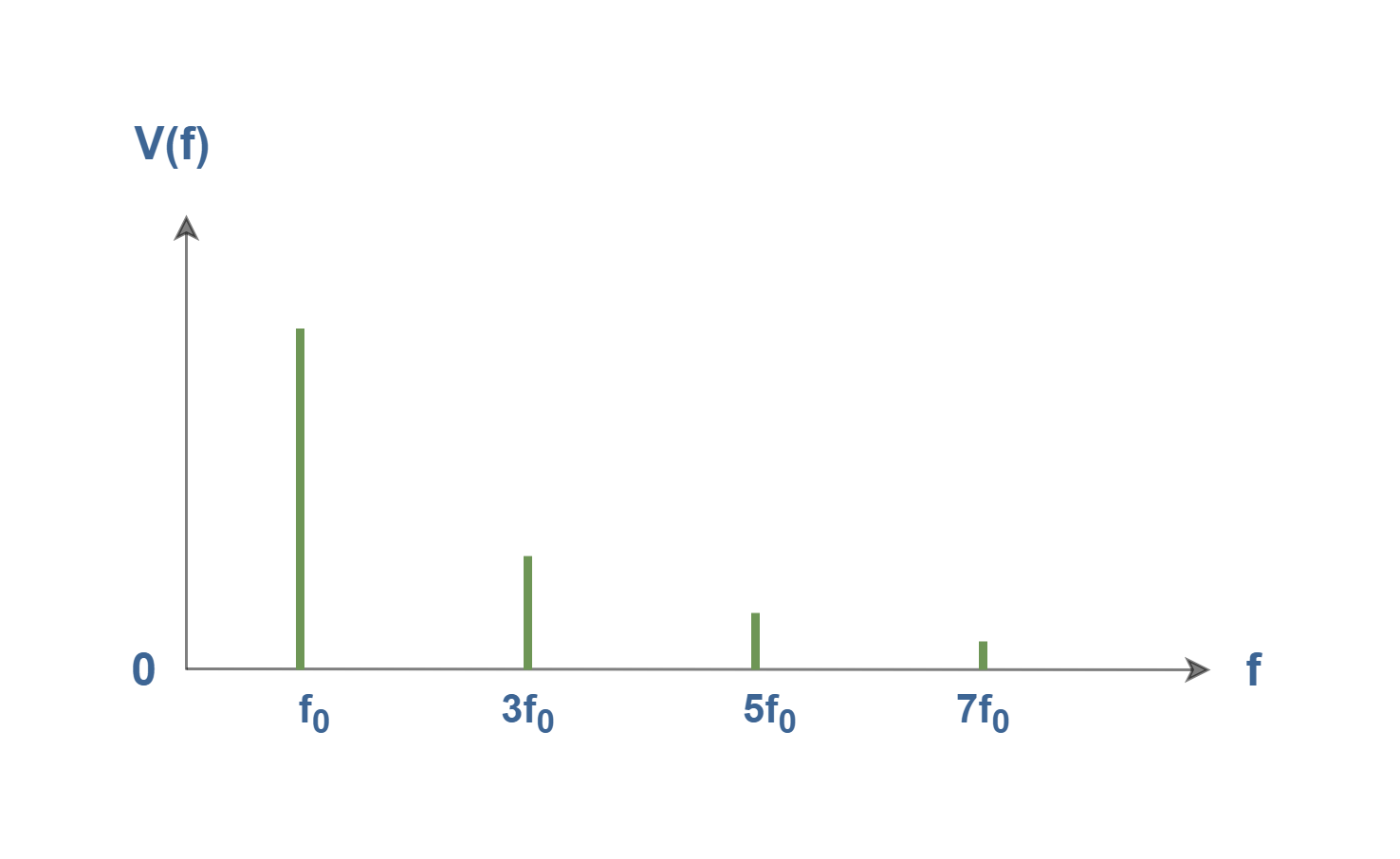
In the spectrum, the amplitude of each of the frequency components is identified. The spectrum of the signal shown in Figure 3-5 is composed of just four frequencies and can be drawn as illustrated in Figure 4.
Figure 4: Line spectra of the synthesized signal v(t)
Basically, sine waves exist only at one frequency. The bandwidth of a single sine wave is zero. It produces a single vertical line on a spectrum analyzer. The x-axis in Figure 4 represents the component frequencies of the signal, whereas the y-axis is the amplitude of those frequencies. This is called a one-sided line spectrum.
The first and lowest frequency is called the fundamental frequency, f0. Each harmonic frequency is an integer multiple of the fundamental. Each nth wave has a frequency that is equal to n times the fundamental frequency i.e., fn = n.f0 , where n is any arbitrary integer; 0, 1, 2, . . . ,∞. The frequency of the first harmonic and the fundamental frequency are the same (n = 1). The wave for n = 2 is called the second harmonic and so on for higher values of the index n.
The wave obtained for (n = 0) is called the DC component. In the above-mentioned signal of v(t), the DC component is zero.
The Fourier Series Method
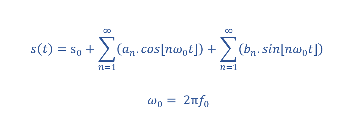
Assume that s(t) is given as an arbitrary periodic signal of period T0. The Fourier series says that the signal s(t) is equivalent to a summation of some weighted sinusoids (harmonics). Equation 2 states a compact Fourier series formula containing the sum of trigonometric functions.
Equation 2: The expression of the Fourier series based on the summation of trigonometric elements
The coefficients s0, an, and bn are called the Fourier Series Coefficients. The process of Fourier analysis consists of computing these three types of coefficients, given an arbitrary periodic function, s(t). The constant s0 is a DC offset and the coefficient an represents the coefficient of the n-th cosine wave and bn of the n-th sine wave.
Equation 3 shows a simple method for computing the first coefficient s0:
Equation 3: Calculation of 0th coefficient
The result of the integration of the target signal s(t) over one period, normalized by the period, is equal to the 0-th coefficient. Therefore, the DC coefficient s0 equals to the area under the given signal waveform in one period i.e., the mean power of the signal.
We can also write Equation 4 for computing an, the coefficients of cosine elements:
Equation 4: Calculation of cosine elements coefficients
The coefficient an is computed by taking the integral of target signal s(t) multiplied with a cosine wave of n-th harmonic frequency over one period T0. The result of the integration is then multiplied (or normalized) by 2/T0 to obtain the coefficient for that particular harmonic. If we do this calculation n times, we get n independent an coefficients.
The process of computing the coefficients of the sine elements, bn, is exactly similar. We can multiply the target signal s(t) sequentially by a sine wave of frequency, nω0. Equation 5 shows the method:
Equation 5: Calculation of sine elements coefficients
Hence, the coefficient bn can be calculated by multiplying s(t) by the n-th harmonic and integrating the expression.
Essentially, our assumption was based on periodic signals and our elements of the basis set were supposed to be eternal sinusoids. But, it is worth mentioning that obviously, no real signal goes on forever. Although, these equations could be a reasonable model for a sinusoidal waveform that lasts a long time compared to the period.
Coefficients make the spectrum
In the above-mentioned equations, the signal s(t) is expressed in the time domain. But, coefficients an and bn (and especially the absolute values of coefficients |an| and |bn|) can represent the amplitude spectrum of the signal s(t) as a function of frequency.
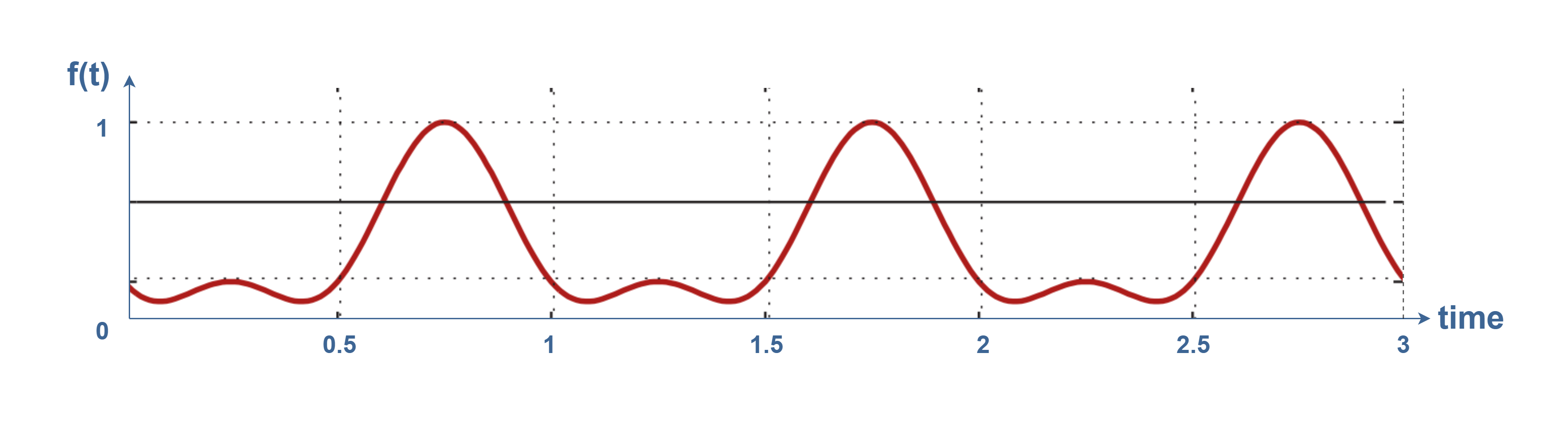
As a general example, we can consider an arbitrary periodic signal f(t) which is expressed in Equation 6:
Equation 6: The example of an arbitrary signal
The time-domain representation of the signal is shown in Figure 5:
Figure 5: The waveform of the periodic function of f(t)
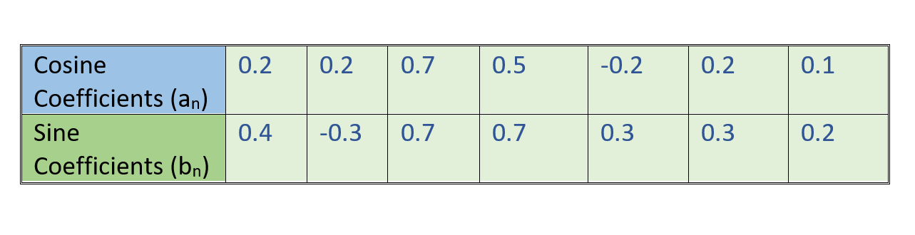
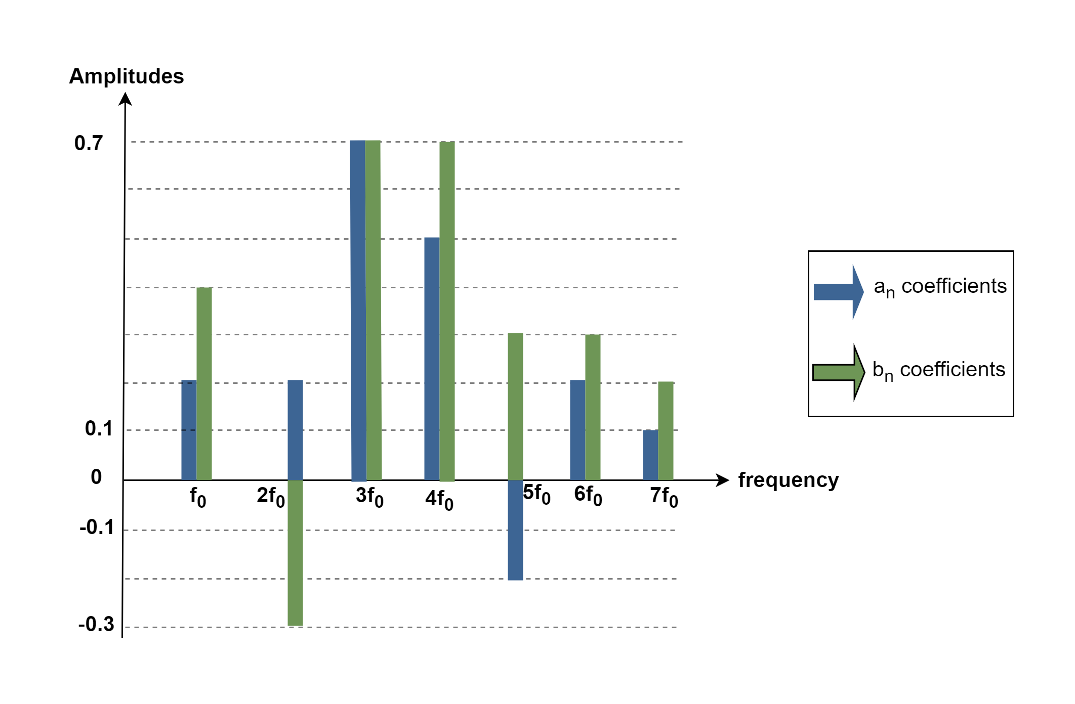
If we apply Equations 3, 4, and 5 on this function to find its Fourier series coefficients, we will find a DC coefficient and some non-zero sine (bn) and cosine (an) factors. Assume that the trigonometric coefficients are calculated as values in Table 1:
Table 1: The coefficient values
Figure6 shows the coefficient values which are plotted as amplitudes in the frequency domain.
Figure 6: Representation of signal f(t) in frequency-domain
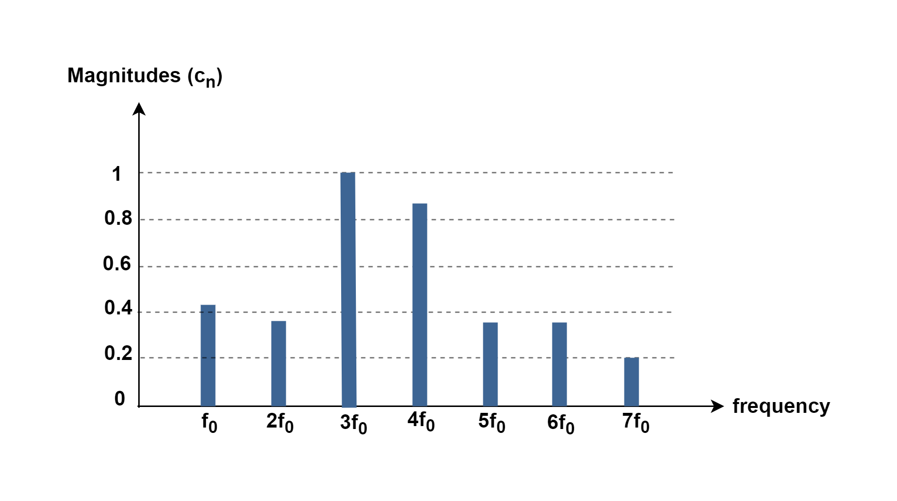
For better understanding and interpretation, a spectrum is supposed to have just one number for each frequency. So, it is better to combine the above-mentioned sine and cosine coefficients into two real-world quantities, called magnitude and phase.
As sine and cosine functions are orthogonal to each other (because of 90 degrees phase shift), and have the same frequency, therefore, we can compute their summation as 2 vectors. This calculation can be done by the root-sum-square (RSS) method for the two coefficients. The magnitude quantity, cn, is one number for each frequency and is computed by the expression in Equation 7:
Equation 7: Calculation of n-th magnitude value of spectrum
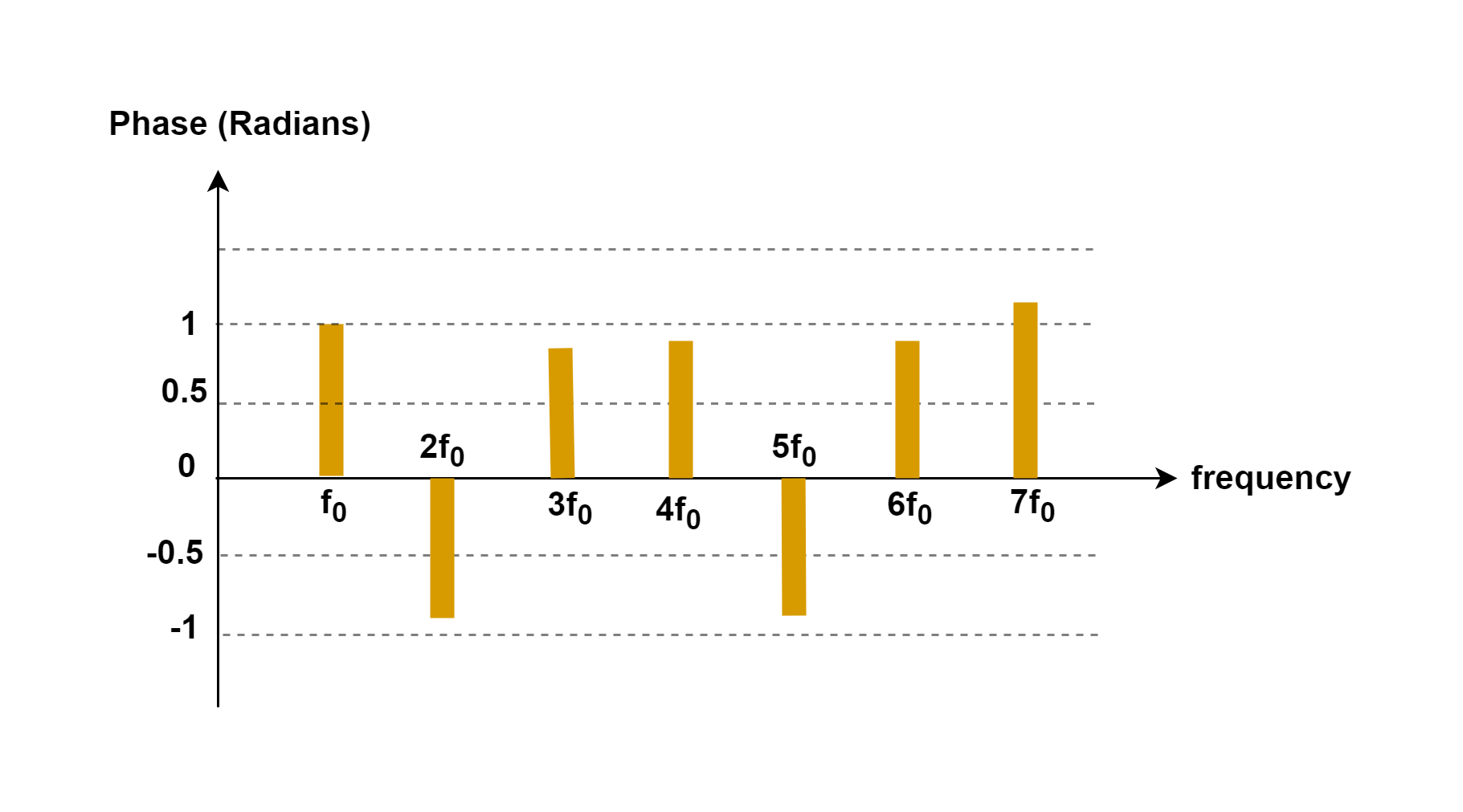
While in some cases the value of amplitude can be negative, the magnitude is always positive. The effect of the sign of the amplitude is now seen in a term called phase, which we calculate in Equation 8.
Equation 8: Calculation of n-th phase value of spectrum
The range of arctan (x) is from −π/2 to +π/2, so it must cover the full phase values.
Figures 7 and 8 show these two quantities on a pair of plots, one for the magnitude and the other for the phase term, both plotted as a function of the harmonic frequencies.
Figure 7: Representation of magnitudes of coefficients in frequency-domainFigure 8: Representation of phases of coefficients in frequency-domain
Normally, the magnitude spectrum is the preferred form in industry rather than amplitude. Its companion, the phase spectrum, usually does not offer practical information and for this reason, it can be ignored most of the time.
Conclusion
Describing continuous signals as a superposition of waves is one of the most useful concepts in many branches of science like electronics, physics, acoustics, optics, and so on.
Based on mathematical Fourier analysis, many types of periodic signals can be decomposed into a combination of sine waves. Also, it is possible to create any periodic signal by the summation of a particular set of harmonic sinusoids.
The result of the synthesis method in Figure 3-5 looks good but it is not a perfect square-wave shape. Because it is not possible to synthesize ideal periodic functions that have discontinuities in their waveforms. Discontinuities are events that occur in zero time. An ideal square wave changes from a maximum positive value to a maximum negative value in zero time. There is no such thing in the real world.
One of the main features of the Fourier Analysis rules is to find the spectrum of different periodic waveforms such as the Saw-tooth wave and so on. Practitioners often need to understand of the basis of spectral estimation of different signals.
Summary
The Fourier analysis technique was invented by Joseph Fourier in the early 19th century.
The term periodic signal is usually applied to periodically varying voltages, currents, or electromagnetic fields. The Fourier series concept is a powerful mathematical tool for better analyzing of time-periodic signals.
The sines and cosines, those having a fundamental frequency and all the corresponding harmonics, are said to form a basis for all periodic waveforms. Each of the sine or cosine waveforms is an element of the basis. This means that not only can sines and cosines be combined to construct any complicated periodic waveform, but also any complicated periodic waveform can be broken down into the sum of sines and cosines.
The Fourier analysis process consists of finding the series coefficients.
If a periodic signal s(t) of period ‘T’ is a real function of time, then, it can be decomposed into a summation including some components:
– A term s0representing the average value or DC component of the signal;
– A sinusoidal term of frequency f (= 1/T) called the fundamental or 1st harmonic term;
– A series of sinusoidal terms with frequencies that are multiples of ‘f’ called harmonics.
By using the Fourier analysis method, it is possible to change the representing domain of the signal from time to frequency.
The more terms we add, the closer we get to what we are trying to achieve.
There is no such thing as an ideal square wave in any physical or electrical system.