Pimoroni Automation 2040 W Mini– An industrial and automation controller with wireless connectivity

Pimoroni Automation 2040 W Mini

A UK-based embedded device manufacturer and supplier, Pimoroni Ltd., has launched an industrial and automation controller that can support 2.4GHz of wireless connectivity– Pimoroni Automation 2040 W Mini. The company has previously worked on a carrier board that could fit the Raspberry Pi Pico W development board, Pimoroni Inventor 2040 W. This time the Automation 2040 W Mini is taking a step forward to be able to hold the all-new Raspberry Pi Pico W.

Pimoroni has provided the hardware platform with many analog channels, powered outputs, buffered inputs, and a relay for industrial applications inside the automation controller. To control pumps, fans, solenoids, chunky motors, and electronic locks, the Pimoroni Automation 2040 W Mini is expected to serve the purpose.

Specifications of Pimoroni Automation 2040 W Mini:

  • Mainboard: Raspberry Pi Pico W
  • CPU: Dual-core Arm Cortex-M0+ running at up to 133MHz clock frequency
  • Memory: 264kB of SRAM
  • Flash memory: 2MB of QSPI flash supporting XiP
  • Wireless connectivity: 2.4GHz wireless
  • ADC: 3x 12-bit ADC inputs up to 40V
  • Digital inputs: 2x digital inputs up to 40V
  • Digital outputs: 2x digital sourcing outputs at V+
  • Relay: 1x relay
  • Buttons: 2x tactile buttons with LED indicators and a reset button
  • Connectors: 1x Qw/ST connector for breakout boards
  • Software: C/C++ and MicroPython libraries
  • Power supply: Compatible with 12V, 24V, and 36V systems, requires a supply of 6-40V and can provide 5V up to 0.5A for lower voltage applications

Pimoroni Automation 2040 W Mini Image

The carrier board has indicator LEDs to show what’s happening with the setup and test the program without having hardware connected. For more digital inputs, outputs, and relays, the company has provided a larger board with 4x digital inputs, 3x digital sourcing outputs, and 3x relays. Also, if the user wants to mount the board inside the switch cabinet or any other electrical enclosure, Pimoroni has provided DIN rail mounts, specifically for the carrier board.

For connecting external breakout boards, the Pimoroni Automation 2040 W Mini carrier board has Qw/ST connector that makes it easy for the user to connect up Qwiic or STEMMA QT breakouts. The developer can directly plug it in with a JST-SH to JST-SH cable.

The board is currently available for sale on the official manufacturers’ website for £39 (approx. $43 USD).

DFRobot Beetle RP2040 mini development board aims for home appliance control

DFRobot Beetle RP2040 mini development board

DFRobot is known for manufacturing many famous electronic embedded devices for home applications, hobbyists, and professional use. In the meantime, Adafruit QT Py received a lot of attention due to its small form factor and improved performance with the latest microcontrollers on board. To capitalize on this momentum, DFRobot has launched the Beetle RP2040 Mini development board with a size measuring 27×20 mm only.

As the name suggests, the development board is equipped with the Raspberry Pi’s in-house silicon tape-out RP2040 microcontroller, which features a dual-core Arm Cortex-M0+ processor core clocked up to 133MHz frequency. On top of that, the RP2040 microcontroller has 264kB internal RAM and supports USB1.1 devices, allowing users to focus on the function implementation instead of spending time on improving the program.

Specifications of DFRobot Beetle RP2040 Mini Development Board:

  • CPU: Raspberry Pi RP2040 microcontroller
  • Clock frequency: 133MHz
  • Internal RAM: 264kB
  • Flash memory: 2MB
  • Power support: 3V3 to 5V DC
  • Interface: USB Type-C port
  • GPIOs: 8
  • Serial communication: 2x I2C, 2x UART, 1x SPI
  • Digital port: 8
  • Analog port: 2
  • Button: 1x reset button and 1x boot button
  • LED: 1
  • USB interface: USB1.1 port
  • Software: C++, MicroPython, Arduino C, Mind+ graphical programming
  • Dimensions: 27x20x4.91 mm
  • Weight: 20 grams without packaging

DFRobot Beetle RP2040 mini development board Pin layout

Thanks to the compact size, the hardware device can be embedded into smaller devices and projects. The company has adopted a beginner-friendly large pad design which is essential to reduce the entry-level barriers and reduce the difficulty of soldering. This rich set of interfaces helps users attach external hardware sensors through various ports available on the DFRobot Beetle RP2040 mini development board.

DFRobot has provided the hardware platform with a BOOT button. If the RP2040 program is running incorrectly, then this can cause a program error and download failure. The solution to this is to hold the BOOT button and plug in the USB cable to the computer at the same time, then the USB drive will be ejected.

DFRobot Beetle RP2040 mini development board is commercially available on the official product page for $6.90. The company has also provided a detailed product wiki page for more information.

Imagination Technologies – Baidu PaddlePaddle co-developed ML library for Model Zoo

Model Zoo Library

A UK-based startup that provides silicon and software IP, Imagination Technologies has partnered with Baidu PaddlePaddle, a provider of artificial intelligence solutions, to co-develop an open-source machine learning library for Model Zoo. The new AI model will cover several AI processing, which includes image classification, image segmentation, and object detection. The jointly developed Model Zoo library is aimed at supporting a wide range of industries, such as consumer, automotive, data center, and desktop markets.

To support the co-developed Model Zoo library, both companies have come together to present more details on September 28, 2022, to offer developers and manufacturers more resources. Imagination Technologies and Baidu PaddlePaddle have been collaborating on various other AI solutions in the past, and the Model Zoo library is an extension to continue their pledge for advanced machine learning algorithms.

“As a leading supplier of processing technology and IP, Imagination enabled Baidu Paddle to construct a highly efficient and flexible software stack solution,” said Yanjun Ma, general manager of Baidu AI Platform and Ecosystem. “The solution is developed based on the deep learning open-source PaddlePaddle framework and Imagination’s heterogenous computing IP through co-designing and optimization. The collaboration will expand to other areas including data center, consumer, and RISC-V.”

The collaboration leverages Baidu PaddlePaddle’s software flexibility with high-performance computation capabilities for Imagination Technologies’ heterogeneous AI accelerator cores. As part of the hardware ecosystem co-creation program, the companies aim to support chip and application developers to create an optimized AI solution for a wide range of deep learning-based use cases.

According to AI experts, the joint program will accelerate the development and deployment of AI models and also provide a verified list of software models, including image classification (EfficientNet), image segmentation (HRNet), and object detection (PP -YOLOE).

“PaddlePaddle is a long-time partner of Imagination, and we share a common vision for the future,” said Wallace Pai, chairman of Imagination China. “We want to ensure that developers and manufacturers have access to the right tools for AI innovation. Our co-created AI ecosystem will continue to leverage our advanced capabilities in AI computing, enabling more support for software and SoC creators in the industry.”

For more information on the Model Zoo deployment, head to the official workshop page for registration. The workshop will cover an end-to-end workflow for the deployment of the Baidu PaddlePaddle model on Imagination Technologies hardware.

Arduino IoT Cloud now supports more ESP32 microcontroller devices

Arduino IoT Cloud

Arduino IoT Cloud has been one of the most popular software tools Arduino has ever built. The cloud-native platform is now able to support more embedded hardware microcontrollers than ever before. With the support of ESP32 and ESP8266 apart from the in-house Arduino boards, the Arduino IoT Cloud is ready to support ESP32 S2, S3, and C3 devices. One of the reasons why most IoT platforms today support ESP32 devices is because of their usability and adaptability in the IoT ecosystem.

ESP32 devices are the most liked microcontrollers for home and hobbyist applications. But in recent times, ESP32 has seen increased adoption for professional and industrial use as well. With Arduino Cloud supporting more ESP32 devices, this means that the end-user devices can now be controlled remotely even after they are deployed in the field.

Arduino IoT Cloud is designed to be a cloud-native platform that can be used to develop software online with the web editor and keep those sketches in the cloud, as well as to deploy and manage end-user-embedded devices. Remote access allows users to create custom dashboards that can be managed remotely from the user’s browser or mobile application.

Specifically, ESP32-S2 and S3 are low-power, high-performance processor cores with the ability to connect wirelessly to the embedded ecosystem. ESP32-S2 comes with a single-core microcontroller system-on-chip, which is designed to be a cost-effective solution with a rich set of input/output capabilities. On the other hand, the ESP32-S3 has a dual-core XTensa LX7 microcontroller that has a clock frequency of 240MHz. The ESP32-S3 has better wireless capabilities to support IEEE802.11b/g/n Wi-Fi and Bluetooth 5 low power.

Arduino IoT Cloud supports many cloud-compatible boards, which allows the developer to leverage an all-in-one solution for IoT development. The user can build visual dashboards to monitor and control embedded devices and also integrate other services in the deployed application. Arduino provides two Arduino IoT Cloud APIs– REST API to allow users to add and configure new Arduino IoT Cloud devices, and Data API (MQTT) to allow users to send and receive variables’ data.

For more information on the Arduino IoT Cloud, head to the product page. We have also previously covered articles on the Arduino Cloud platform.

Ultrasonic Dog Chaser with Repelling Strobe Light and Extra Functions

Author: Irena Antoniuk, Technical Documentation Apps Engineer, Renesas Electronics

Cover photo: www.depositphotos.com

Introduction

This article aims to demonstrate how to design a dog chaser. The system is designed using the HVPAK™ SLG47105V macrocells and other internal and external components within the GreenPAK to control a piezo element and a 3W LED.

The Dog Chaser has three modes: Dog Repeller, Dog Training, and Flashlight. In the Dog Repeller mode, a powerful ultrasonic signal and a strobe light disorient the dogs. In the Dog Training mode, the lower power ultrasonic signal is used, this signal makes dogs annoyed, but not disoriented. The Flashlight mode is just a powerful flashlight that can be useful when additional lighting is needed.

1. Block Diagram and Circuit Design

The Block Diagram is shown in Figure 1.

Figure 1. Block Diagram

As can be seen in Figure 1, the Dog Chaser contains three modes, which are selected by a switch. Dog Repeller or Dog Training Mode is ON when the switch is in the appropriate position and the push button is pressed. To turn ON the Flashlight, there is no need to press the button, just switch to Flashlight Mode. The device is considered turned off when the switch is in the middle position (Dog Training Mode) and the push button is not pressed.

The circuit is powered by a Li-ion battery, so the VDD is between 3.0 V and 4.2 V. The LED intensity depends on voltage VDD, so the DC-DC Boost Converter is added to provide the constant necessary current to the LED.

The Full Circuit Schematic is shown in Figure 2.

Figure 2. Full Circuit Schematic

The GreenPAK design is shown in Figure 3. The complete design file can be found here. It was created in free GUI-based GreenPAK Designer software – a part of Go Configure Software Hub.

Figure 3. GreenPAK Design

The 390.6 kHz signal with a 50% duty cycle is created by OSC1 and goes to the 2-bit LUT0, which controls the Booster circuit through the HV PIN 8. When the maximum LED current of 700 mA is reached, the ACMP1 sets the 2-bit LUT0 to 0 and pulls down the HV PIN 8 keeping the current through the LED at the same level. It should be noted, that the external MOSFET must be selected with the lowest possible gate threshold voltage high enough current. For example IRLL3303. The results of Boost can be found in Figure 4 and Figure 5. The HV PIN 8 is represented in blue and the ACMP1 is in green.

Figure 4. Boost Operation – 3.2 V
Figure 5. Boost Operation – 3.4 V

The necessary LED mode is selected by 3-bit LUT3 and DFF3. These signals go to HV PIN 7 of the HV OUT CTRL0 which is configured as a Half-Bridge and acts as a switch for the LED. So, the LED is ON when PIN 7 is LOW and vice versa. Also, the internal low-side MOSFET (PIN 7) is used as a current sensor. Its RDS On is about 150 mOhm which is perfect for our purpose.

2. Dog Repeller Mode

The Dog Repeller mode includes two parts the Ultrasonic signal at full power and the LED strobe light.

The OSC1 generates the 100 kHz signal which goes through DFF2 and DFF4 and decreases to 25 kHz. Then this signal goes to PH input of HV OUT CTRL1, which is configured as Full Bridge. The Enable signal Piezo ON is generated by 3-bit LUT6 to be HIGH only when Dog Repelling Mode or Dog Training Mode is selected. To achieve the necessary amplitude the 4:40 voltage transformer is used. PIN 9 and PIN 10 are connected to the primary winding and the piezo element is connected to the secondary winding (see Figure 2). The resulting signal in the piezo element is a ~37 V amplitude ultrasound signal (Figure 6).

Figure 6. Piezo Output Signal in the Dog Repeller Mode

The LED strobe light is used to increase the dog`s disorientation. In this case, the 3 W LED is connected to PIN 7 of HV OUT CTRL0 with an input of 11.65 Hz. The resulting LED signal is shown in Figure 7.

Figure 7. LED Signal Output in the Dog Repeller Mode

3. Dog Training Mode

The Dog Training mode includes a 25 kHz signal with ~17 V amplitude when the battery is charged (4.1 V) and ~12 V when the battery is discharged (3.1 V). The additional 33 Ohm resistor is connected to PIN 9 of the primary winding of the voltage transformer and limits the current to ~80 mA to decrease the power of the piezo output signal (see Figure 8 and Figure 9).

Figure 8. Piezo Output Signal in the Dog Training Mode (VDD – 4.1 V, amplitude – 17 V)
Figure 9. Piezo Output Signal in the Dog Training Mode (VDD – 3.1 V, amplitude – 12 V)

4. Flashlight

In the Flashlight mode, the DFF3 sets the Enable signal OE0 of the HV OUT CNTR0 to HIGH, and the 3-bit LUT3 set the IN0 to LOW, so the output of PIN 7 is continuously LOW and the LED is continuously ON.

5. Battery Discharge

As the device is powered by a Li-ion battery, for example, a 18650 cell, there is a need to control the discharge level to prevent cell damage (assuming the battery does not have its own protection circuit). The comparator ACMP0 monitors the VDD level and if the voltage is less than 3072 mV the circuit is cut off. When the Dog Training Mode or Dog Repeller Mode is selected and the push button is not pressed, comparators ACMP0 and ACMP1, HV OUT CTRL0, HV OUT CTRL1, and OSC1 are in Sleep Mode thus consuming close to 0 current. The device is considered turned off when the switch is in the middle position and the push button is not pressed.

Conclusion

The article describes how to configure the HVPAK to create a Dog Chaser. The results prove that the circuit works as expected, and the HVPAK is capable of acting as the control module for the piezo element and the powerful LED.

The Dog Chaser has three modes. The Dog Repeller mode is powerful ultrasonic and strobe light signals that disorient the dog. The Dog Training mode is a lower-power ultrasonic signal which helps to train the dog. The last mode is a powerful flashlight.

Limited 15% Off For Biggest Battery Rugged Phone

Well-known global smartphone company OUKITEL introduced WP19 world’s first biggest battery-rugged smartphone, which is designed to sustain the unpredictable tough environments that regular phones can not withstand. Apart from the impressive battery, it is also equipped with 8GB RAM & 256GB ROM storage, the latest night vision camera, and more. This is an ultra-military-grade rugged smartphone that can meet all your outdoor toughness and durability needs.

Thanks to the overwhelming favor and support from our fans, OUKITEL today announces that WP19, this flagship smartphone, will be on promotion and offer an attractive discount of up to 15% off from October 3rd to October 9th on Amazon. You can get a WP19 rugged phone at the price of USD 382.49 only.

21000mAh Biggest Battery with Impressive Night-vision Camera

One of the most impressive features is the massive battery capacity. OUKITEL WP19 comes with 21000mAh world’s biggest battery, which is up to 4 times the average phone battery capacity (5000mAh). This is the best choice for outdoor enthusiasts and those who travel frequently. The WP19 durable smartphone can support 7 days of daily use maximum after a single charge. It charges from 0-80% in 3 hours with a 33W rapid recharging function. Moreover, this powerful WP19 is a portable power bank since its reverse recharging process allows you to recharge your other devices (smartwatch, TWS earbuds, phones, etc.).

64MP SAMSUNG S5KGW3 primary camera, SONY IMX350 20MP night vision Camera, and 2MP macro camera allows you to shoot professional photos, even taking a nice one with clarity in the evening. Supported by the 4 built-in IR emitters, you could easily find out the potential threat in the darkness with a night vision camera.

Immersive Experience and Seamless Operation

This is a 6.78-inch FHD+ display phone and a 90Hz refresh rate. It is the latest Android 12 system. Equipped with a MediaTek Helio G95 processor with 8GB RAM and 256GB ROM, WP19 offers users fast and smooth uploads & downloads, gaming, browsing, and more. In addition, the WP19 rugged phone is IP68 & IP69K waterproof, dust-resistant, and  MIL-STD-810H certified military standard, which means it can withstand any tough environment. WP19 also comes with fingerprint & face ID, NFC Google Pay, customized key, etc.

What is OEM Service in Electronics

You have probably heard the term “OEM” before and chances are that you are within arm’s reach of several OEM products wherever you are seated presently. OEM, short for “Original Equipment Manufacturer”, refers to a company that produces systems or components that may be used in another company’s end products. OEMs are usually the first inventors and designers but not the sellers of the finished products. They license out the products they make to be used as components in another’s company products, hence marketing them under the other company’s brand name.

What an OEM Service Means

So an OEM service is typically a collaboration between a supplier who shows willingness and ability to make customized designs of products according to the needs and specifications of a buyer. Many brand-name electronics and appliances we see today are good examples of OEM services. A common one is a relationship that exists between a manufacturer of individual electronic components and a company such as Samsung or Sony that put the OEM parts together to make their own finished products. Another great example is the automotive industry. The car you bought was not entirely manufactured by the car company; some parts of the car such as the airbags, navigation units, spark plugs, air conditioners, dashboards, sensors, and even the engines, were manufactured by or outsourced from other companies. You will be shocked to know how small the efforts put by the company in supplying the parts were, compared to branding and marketing.

Is it also the computer manufacturers who integrate several OEM parts such as software and processors into the solutions they sell, or the Ralph Lauren company that bought customized fasteners from a maker of buttons to be used in a shirt that boldly carries the banded RL stamp on it? OEM services are literally scattered everywhere around us. The question is …

Why OEM Service?

Partnering with an OEM helps enterprises increase efficiency, reduce labor cost, streamline processes, save time and save money.

OEM products are usually cheaper due to an increased level of production. “The OEM excels in building one product and one product only, and thrives by building hundreds of thousands, or even millions of those products on a cost-effective, streamlined basis,” says TheStreet. When an OEM undertakes contract manufacturing of components, the reseller is allowed more time to focus on its core capabilities and processes as it would not have to develop each part or system by itself. The company also does not have to incur the extra costs or increased capacity involved in manufacturing those components in-house (like having to build manufacturing facilities). All they need to do is just integrate the outsourced parts into their system and sell under their own brand name.

OEMs also deliver a good return on investment to the partnering company by ensuring they make sure products that live up to expectations.

“OEM parts, components and products extend the life of the partnering company’s product with a no account casinos list, thus maintaining top performance and saving money with replacement parts and increasing the company’s financial bottom line.”

Most organizations now try to reduce their OEM and vendor complexity by just patronizing a centralized support or service system, as like David Subia rightly said in his IBM blog,

“trying to support IT solutions that include products from several vendors would be like having to manage the roughly 30,000 parts that make up your car. Would you have multiple vendors managing each part, or go to one trusted mechanic to ensure that it performs efficiently, safely, and at minimal cost to maintain?”

PCBWay OEM Service

With several years of experience in PCB prototype and fabrication, PCBWay is one of the most experienced and trusted PCB manufacturing companies in China.

PCBWay in partnership with strategic alliance partners has a contract manufacturing service that includes product design, product development, engineering validation, PCBA manufacturing service, and supply chain management. This One Stop Shop Solution aims at simplifying and managing all the complexities at one stop, providing all the services you may need – from early design concepts to packaging fully assembled devices that are ready for shipment. They work closely with manufacturers throughout the whole process to ensure reduced cost while maintaining performance.

PCBWay OEM services focus on achieving product manufacturing and intelligence while the clients focus on product performance. The company page reveals that “PCBWay OEM uses the Internet, Internet of Things, and cloud technology to deeply transform the entire value chain of the electronics manufacturing industry, realize centralized order input, digital engineering technical services, and highly digital workshops, helping factories to produce according to customer needs.”

PCBWay OEM Services provide high-quality electronic products for global brands while maintaining quality and on-time supply chain services.

Examples of PCBWay-OEM Solutions and Design Cases

PCBWay OEM has recorded quite a number of success stories already, let’s take a quick look at some of them.

Client: A high-tech technology client that manufactures smart grid solutions, energy-efficient power generation, and distribution solutions.

Scope of Contract: Design and production of PCB board, selection and replacement of domestic chips, molding and plastic injection, assembly of finished products, and final inspection testing and certification performance.

Achievements: PCBWay-OEM was able to reduce the total production cost by 15%, successfully helped the client solve the global chip shortage problem, met all the US and European requirements, and still had a fast turnaround time completing PCB designs and delivering some samples to clients in 30 days.

The Fengmi step-less frequency conversion smart fan featuring a 99-gear speed control, a mobile APP intelligent control, 16 feather fan blades, and power saving mode, took only 5 months from research and development to mass production.

PCBWay-OEM did not only undertake the material procurement and overall production process, but it also saw the intelligent upgrade of the fan. It utilized its strong supply chain support to ensure the quality of each product. The circuit boards, SMT, molds, sheet metal and assembled finished products were all completed by self-operated factories.

Quantities Delivered: 100,000 units

Customer’s Requirement:

“We would like to protect the sensor against humidity, dirt, or any other damage that could be introduced due to the fact that it is in contact with the skin and the air. But this protection layer should be transparent in order to help the performance of the sensor. Do you have any special resin or something to protect it? We were thinking of something that could be adapted to any shape.”

Conclusion

In summary, PCBWay-OEM services help clients complete integrated R&D tasks faster and better, achieve rapid and sustainable development, and eventually deliver stable, reliable, and efficient products. Feel free to contact them for a quote on design concept development, engineering services, appearance models, functional prototype, quick turn tooling, injection molding, or contract manufacturing.

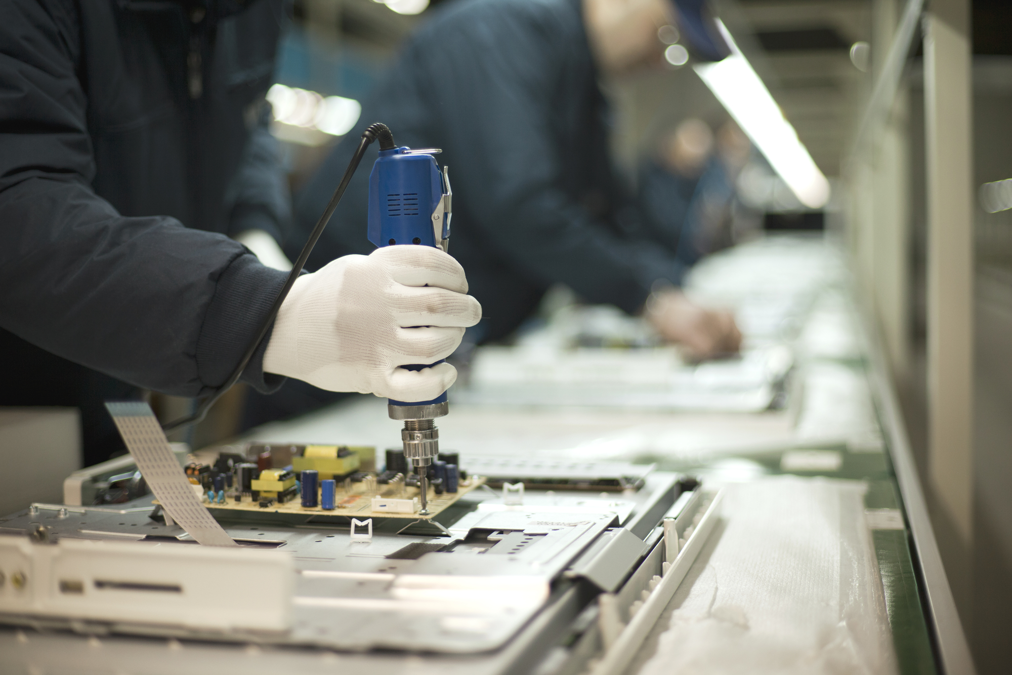
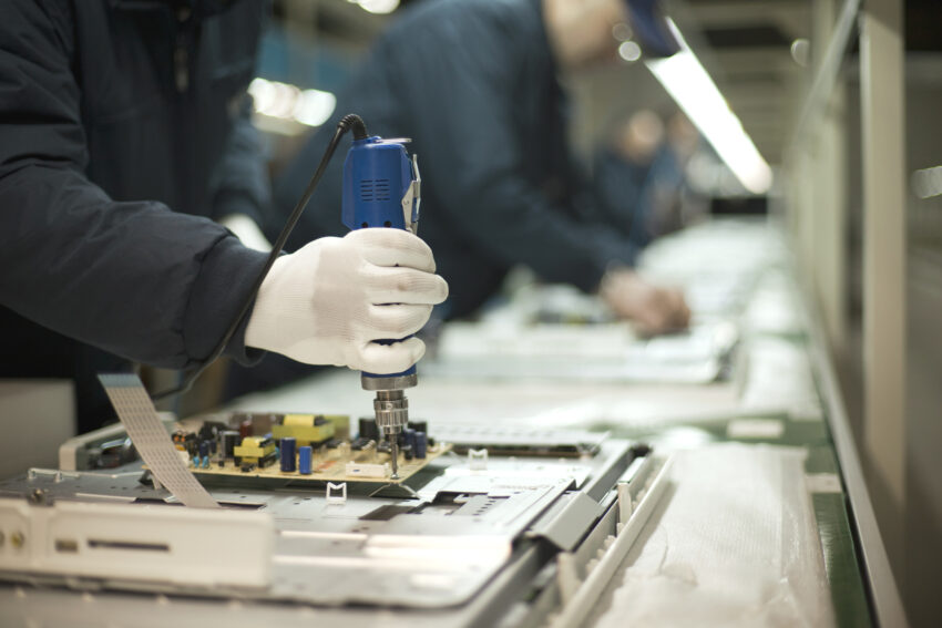
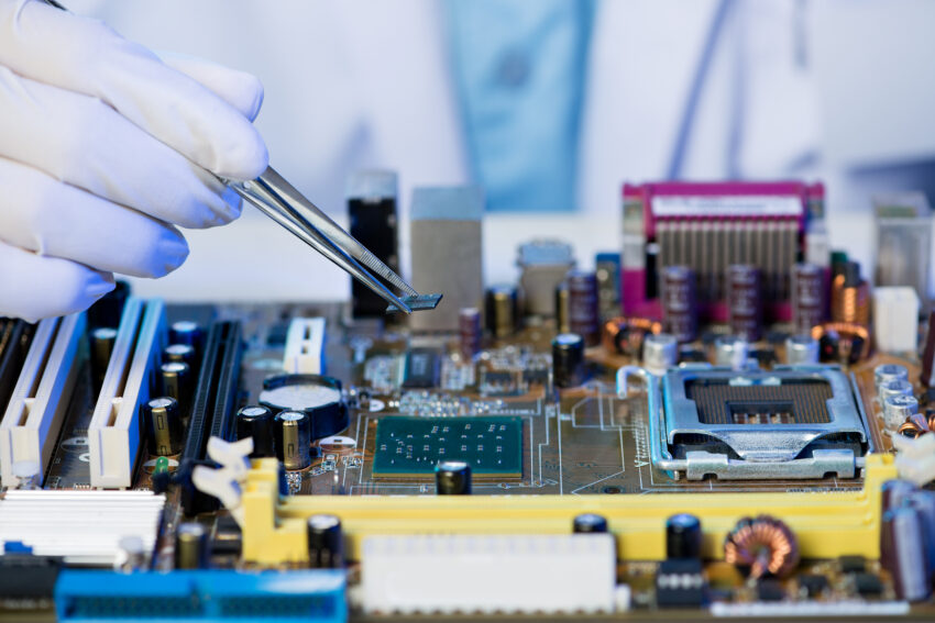
(stock photos from depositphotos.com)

New MangoPi MQ Quad SBC comes with an Allwinner H616 processor and a RPi Zero W form factor

Single board computer specialist Mango Pi, recently announced the launch of its new Mango Pi MQ Quad Single board computer equipped with an Allwinner H616 quad-core Arm Cortex A-53 SoC.

The Allwinner H616 system-on-chip which was launched back in 2017, has so far made its way into various single board computers. The chip features a 4-Core Cortex-A53 ARM CPU running @ up to 1.5 GHz, an ARM Mali-G31 MPU graphics processor running @ 650 MHz with OpenGL 3.2, Vulkan 1.1 and OpenCL 2.0 API support, AES and SHA acceleration engines, and video decoding and encoding hardware. Compared with its counterpart, the Allwinner D1 Risc-v processor found in the company’s other MQ Pro SBC, this chip seems to offer better out-of-the-box software due to its ARM-based processor.

The compact MQ Quad SBC also comes with up to 1GB of DDR3L RAM, one HDMI port, WiFi 4, Bluetooth 4.2 support, microSD card reader, a set of ports for connecting power, display, peripherals, and a 40-pin, Raspberry Pi-compatible general purpose input/output (GPIO) header.

The board was designed to mimic the footprint of the Raspberry Pi Zero W form factor, so if you have been struggling to find stock of the popular RPi board, you may just have found a perfect alternative in it.

Features and Specifications Include:

  • Allwinner H616 quad-core Cortex-A53 processor running at 1.5 GHz
  • Mali-G31 MP2 GPU running at up to 650 MHz
  • 1GB DDR3L RAM
  • MicroSD card slot located at the top of the board
  • Footprint for SPI flash at the bottom of the board
  • 1x mini HDMI 2.0 port up to 4K@60Hz resolution
  • 802.11 b/g/n WIFI 4 and Bluetooth 4.2 support
  • Ceramic GPS antenna with uFL connector
  • 2x USB Type-C ports (1x OTG and 1x Host)
  • 40-pin Raspberry Pi compatible, color-coded GPIO header
  • 18-pin MISC FPC connector with USB, Ethernet, and additional GPIOs
  • Power Supply: 5V via USB port; 5V GPIO header and pogo pins; AXP313A PMIC
  • Dimensions: Raspberry Pi W form factor (65 mm x 30 mm)

Software support for the board includes Ubuntu, Android 10, other GNU/Linux-based OS, and the OpenWRT-based Tina Linux embedded software designed for devices with Allwinner chips.

Further details on the Mango Pi MQ Quad SBC can be found on AliExpress where it currently sells for $26.74 or $29.64 if you want it with an all aluminum heatsink/case, so that while heat is only drawn from the SoC, it is dissipated into the decently sized piece of metal.

The product page of the company’s website also has other useful resources such as the board schematics, the reference design, and the datasheet.

StarFive Revamps its RISC-V-Based SBC with Enhanced Capabilities as the VisionFive 2

VisionFive 2

StarFive, the RISC-V software, and hardware ecosystem leader, recently announced the world’s first high-performance SBC with an integrated GPU. The VisionFive 2 is an upgraded version of StarFive’s first RISC-V-based Single Board Computer (SBC), the VisionFive 1.

The processor work frequency, multimedia processing capabilities, scalability, and other aspects of VisionFive 2 have all been significantly enhanced over its previous iteration. VisionFive 2 is the best affordable RISC-V development board ever due to its excellent performance and affordable pricing.

The VisionFive 2 is built on StarFive’s latest JH7110 system-on-chip (SoC), which not only eliminates the previous JH7100 chip’s known issues but also doubles the number of useable processors from two to four and boosts clock speed from 1GHz to 1.5GHz. Moreover, StarFive added a Graphics Processing Unit (GPU) to the board, further boosting the performance and enhancing the desktop experience.

It has several multi-media peripherals including USB 2.0, USB 3.0, MicroSD Card slot, 3.5mm audio jack, RJ45 Ethernet connectors, and an eMMC socket. The board also provides 40 pin GPIO Header. Each GPIO pin is capable of 5V DC output with a minimum of 3A of current. Several GPIO pins also support communication protocols like I2C, SPI, and UART for better interfacing with other devices.

VisionFive 2 board layout

The VisionFive 2 supports a wide range of displays with multiple video output ports. It contains a 2-lane MIPI DSI display port, supporting up to 1080p at 30fps, and a 4-lane MIPI DSI display port, supporting up to 2K at 30fps in both single display and dual display modes. It also features an HDMI 2.0 port, supporting up to 4K at 30fps or 2K at 60fps. Moreover, the VisionFive 2 has a 2-lane MIPI CSI camera port that supports up to 4K (3840 x 2160) pixels at 30fps.

Enhancing Desktop Experience with the high-performance VisionFive 2 SBC

Overcoming the limitations and shortcomings of its predecessor, the VisionFive 2 offers a high-performance experience in a compact form of 100mm x 72mm. With its decent power consumption, communication peripherals, and GPIO support, it is an ideal portable system for several applications. Moreover, it supports the mainstream Linux distributions, making it user-friendly and convenient.

StarFive is using Kickstarter to fund the development of the boards, with tangible incentives starting at $46 for the early bird 2GB versions. This is a significant discount from the retail price of the original VisionFive, which was $179.

Dragon Li’s compact Bajiu Lite Dev Board Provides an Easy Route to Low-power FPGA and RISC-V projects

Dragon Li Studio is set to launch the small, convenient, and out-of-the-box Bajiu Lite dev board – an open-source resource-rich FPGA development board integrated with RISC-V SoC. The FPGA specialist has tapped into its over-a-decade years of experience in hardware and software to design something like this, which aims at providing an easy route to low-power FPGA and RISC-V projects.

“We are committed to building the most convenient RISC-V development board, which is convenient for you to quickly customize the CPU you need according to your needs,’ the company says. “Bajiu Lite is a resource-rich FPGA development board with 20k LE (Logic Elements), 36 multipliers, and up to 5 PLLs (Phase-Locked Loops). It can easily run at frequencies above 150MHz with very low power consumption. It is small, convenient and dedicated to facilitating rapid FPGA development right out of the box.”

Bajiu Lite development board features and specifications include:

  • 20,000 Logic Elements
  • 36 Multipliers
  • 5 Phase-Locked Loops
  • 1 MB of embedded RAM from an Efinix Trion T20F169 FPGA
  • 1x MIPI Camera Serial Interface (CSI) port
  • 1x MIPI Display Serial Interface (DSI) port
  • 3x LEDs
  • 3x Buttons
  • 10x General Purpose Input / Output (GPIO) pins
  • 128 MBits flash
  • 2x UART buses
  • FTDI JTAG debugger

Funnily enough, the name of the board seems to have a unique reference to the things it can do. “Bajiu’ means 8 * 9 = 72, which means the mythical Monkey King’s thousand variations. We chose this name because Bajiu Lite can be used to implement nearly any logic,” the company explained.

Meanwhile, a customizable 32-bit open-source RISC-V SoC soft core called the CRiscV was designed alongside the Bajiu Lite dev board. According to Dragon Li, adapting the VexRisc-V-based SoC soft-core with the board will “allow users to implement powerful tools quickly, including those related to vision processing, neural networks, RISC-CPUs, robotics, and other common applications.”

The board also utilizes the Efinix software tools to build designs for FPGAs. They are easy to set up and straightforward to use. The company has made a quick guide on how to go about installing and using this software available on their GitHub repository, alongside other useful details including the Getting Started Guide, the CRiscV, and the open source documentation.

You can also check the Crowdfunding CrowdSupply page for more information and sign up so you’ll be notified when the project eventually launches. No word on the launch date or price yet but hopefully, that should be any moment from now.

TOP PCB Companies