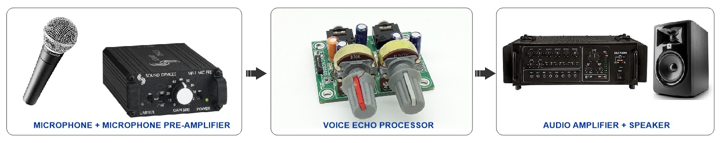
The voice echo or digital delay sound effects project presented here is suitable for applications such as Karaoke, multimedia, musical instrument effects, electronics toys, animatronics, etc. The project is based on PT2399 chip, with an operating supply of 5V DC, and approx. 30mA current consumption. Two potentiometers are provided to set the delay and repeat. The delay range is adjustable from 50ms to 280ms.
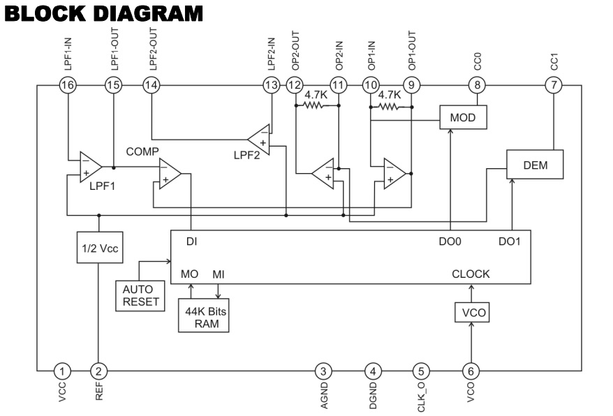
The PT2399 is a single-chip echo processor IC utilizing CMOS technology. It accepts analog audio input signal, and a high sample rate ADC converts the analog signal into a bit stream that is stored in internal 44Kbit RAM. After processing the bit stream it will be de-modulated by DAC and lowpass filter. The overall delay time is determined by the internal VCO clock frequency, and the user can easily change the VCO frequency by changing the external resistance. The PT2399 performs low distortion (THD<0.5%@0.5Vrms) and low noise (No<-90dBV) characteristics for audio purposes.
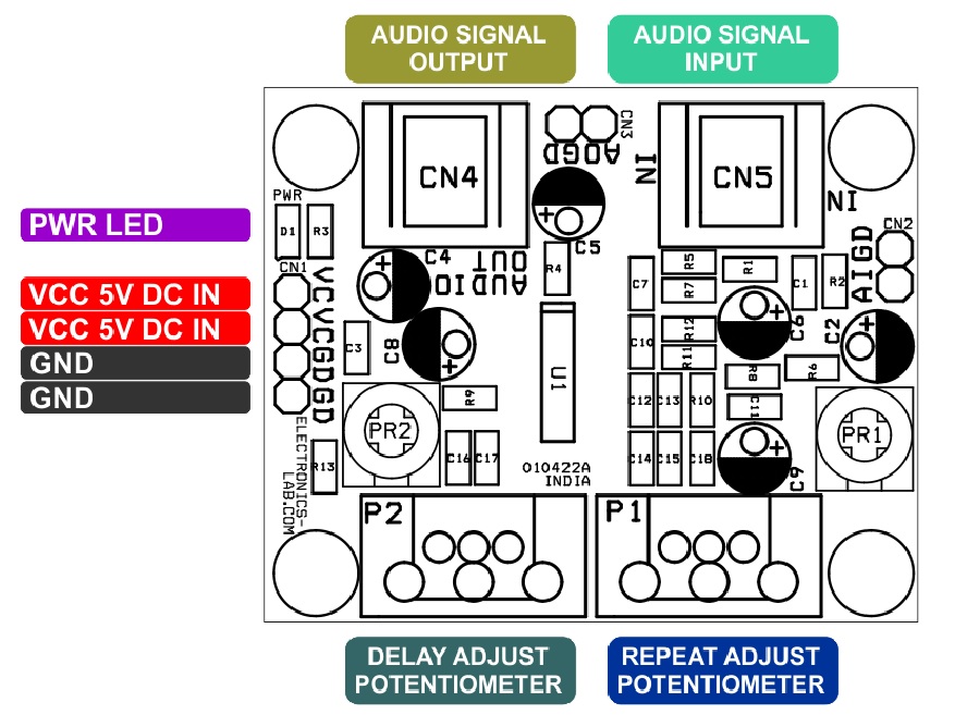
Connections and Other Important Details
- CN1: Power Supply Input >> Pin1 = VCC 5V DC, Pin2 = VCC 5V DC, Pin3 = GND, Pin4 = GND
- CN2: Audio Signal Input from Musical Instruments or Microphone Preamplifier >> Pin1 = Audio Signal Input, Pin2= GND
- CN3: Audio Signal Output >> Pin1 = Audio Signal Output, Pin2= GND
- CN4: Optional 3.5MM EP Female Connector for Audio Output
- CN5: Optional 3.5MM EP Female Connector for Audio Input
- PR1 or P1: Potentiometer to Adjust the Delay
- PR2 or P2: Potentiometer to Adjust the Repeat
- D1: Power LED
Features
- Power Supply 5V DC @ 30mA
- Delay Range 50ms to 280ms (Read Note 1)
- Accept Standard Audio Signal
- On Board Potentiometer for Delay Adjust
- On Board Potentiometer for Repeat Adjust
- On Board Power LED
- EP Socket for Audio Signal Input and Output
- Optional 2 Pin x 2 Header Connector for Audio Input and Output
- 4 x 3MM Mounting Holes
- PCB Dimensions 48.10 x 38.58mm
Applications
- KARAOKE Mixer
- CD/DVD Player/Recorder
- Multimedia
- Animatronics
- Music Instrument effecter
- Electronics Toy
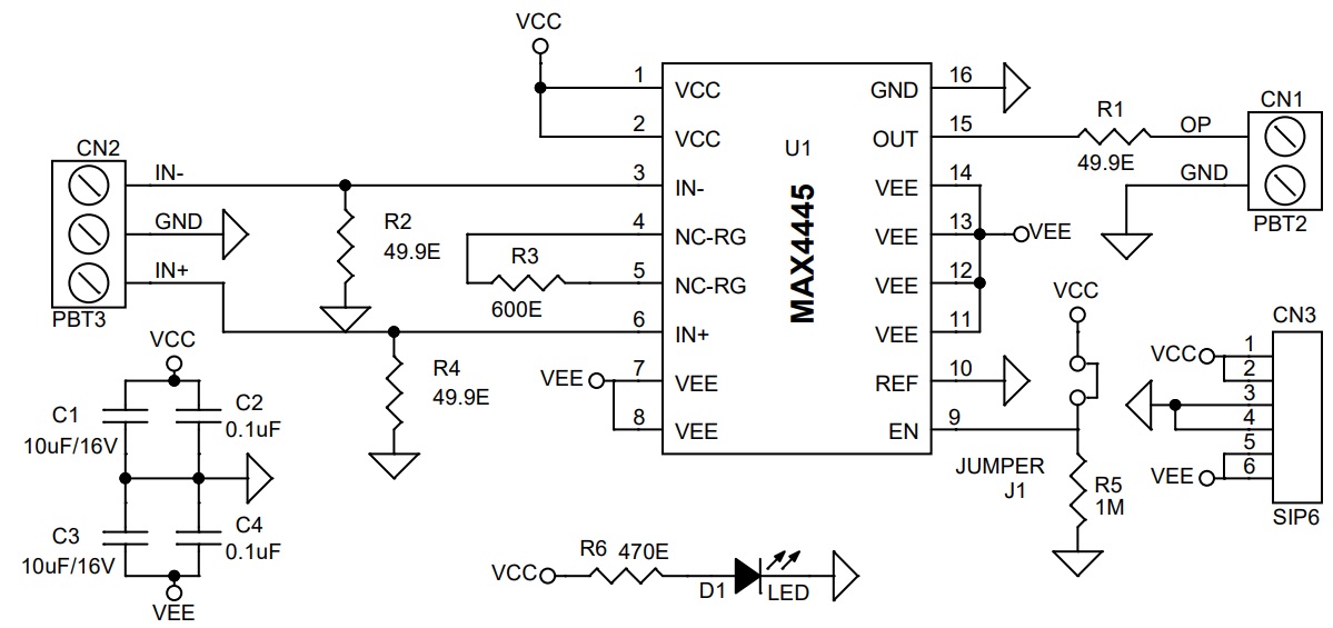
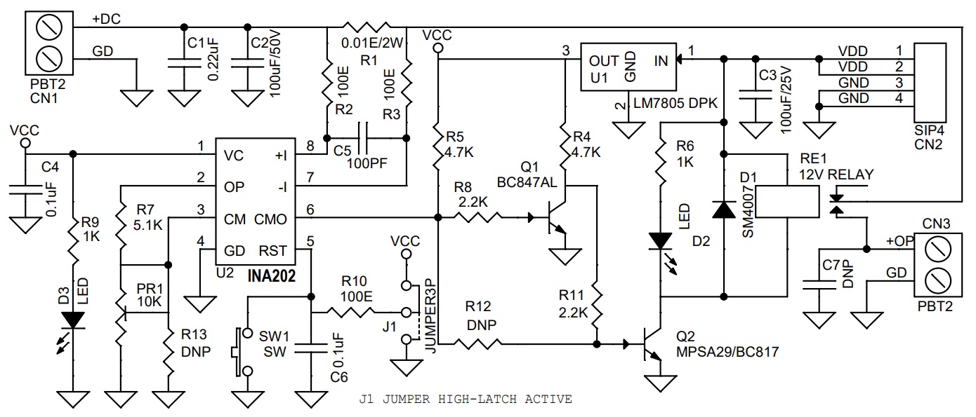
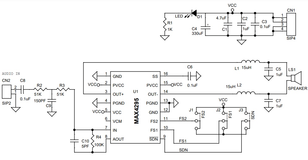
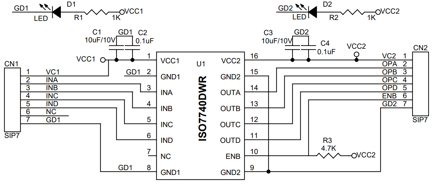
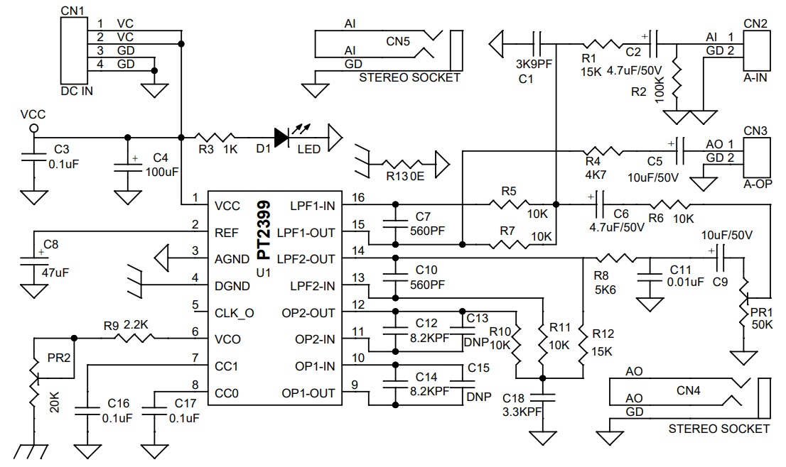
Schematic
Parts List
| NO. | QNTY. | REF. | DESC. | MANUFACTURER | SUPPLIER | PART NO |
|---|---|---|---|---|---|---|
| 1 | 1 | CN1 | 4 PIN MALE HEADER PITCH 2.54MM | WURTH | DIGIKEY | 732-5317-ND |
| 2 | 1 | CN2 | 2 PIN MALE HEADER PITCH 2.54MM | WURTH | DIGIKEY | 732-5315-ND |
| 3 | 1 | CN3 | 2 PIN MALE HEADER PITCH 2.54MM | WURTH | DIGIKEY | 732-5315-ND |
| 4 | 2 | CN4,CN5 | 3.5MM STEREO EP SOCKET FEMALE | CUI AUDIO | DIGIKEY | CP1-3525N-ND |
| 5 | 1 | C1 | 3K9PF/50V SMD SIZE 0805 | YAGEO/MURATA | DIGIKEY | |
| 6 | 2 | C2,C6 | 4.7uF/50V OR 16-25V ELECTROLYTIC | PANASONIC | DIGIKEY | P10321-ND |
| 7 | 3 | C3,C16,C17 | 0.1uF/50V SMD SIZE 0805 | YAGEO/MURATA | DIGIKEY | |
| 8 | 1 | C4 | 100uF/16V OR 25V ELECTROLYTIC | UNITED CHEM | DIGIKEY | 565-EMHL250ARA101MF80GCT-ND |
| 9 | 2 | C5,C9 | 10uF/50V ELECTROLYTIC | NICHICON | DIGIKEY | 493-12569-1-ND |
| 10 | 2 | C7,C10 | 560PF/50V SMD SIZE 0805 | YAGEO/MURATA | DIGIKEY | |
| 11 | 1 | C8 | 47uF/16V OR 25V ELECTROLYTIC | NICHICON | DIGIKEY | 493-10997-1-ND |
| 12 | 1 | C11 | 0.01uF/50V SMD SZIE 0805 | YAGEO/MURATA | DIGIKEY | |
| 13 | 2 | C12,C14 | 8K2PF/50V SMD SIZE 0805 | YAGEO/MURATA | DIGIKEY | |
| 14 | 2 | C13,C15 | DNP | |||
| 15 | 1 | C18 | 3K3PF/50V SMD SIZE 0805 | YAGEO/MURATA | DIGIKEY | |
| 16 | 1 | D1 | LED RED SMD SIZE 0805 | LITE ON INC | DIGIKEY | 160-1427-1-ND |
| 17 | 1 | PR1 | 50K POTEMTIOMETER PCB MOUNT 16MM | BOURNS INC | DIGIKEY | PDB181-K220K-503B-ND |
| 18 | 1 | PR2 | 20K POTENTIOMETER PCB MOUNT 16MM | BOURNS INC | DIGIKEY | PDB181-K420K-203B-ND |
| 19 | 2 | R1,R12 | 15K 5% SMD SIZE 0805 | YAGEO/MURATA | DIGIKEY | |
| 20 | 1 | R2 | 100K 5% SMD SIZE 0805 | YAGEO/MURATA | DIGIKEY | |
| 21 | 1 | R3 | 1K 5% SMD SIZE 0805 | YAGEO/MURATA | DIGIKEY | |
| 22 | 1 | R4 | 4K7 5% SMD SIZE 0805 | YAGEO/MURATA | DIGIKEY | |
| 23 | 5 | R5,R6,R7,R10,R11 | 10K 5% SMD SIZE 0805 | YAGEO/MURATA | DIGIKEY | |
| 24 | 1 | R8 | 5K6 5% SMD SIZE 0805 | YAGEO/MURATA | DIGIKEY | |
| 25 | 1 | R9 | 2.2K 5% SMD SIZE 0805 | YAGEO/MURATA | DIGIKEY | |
| 26 | 1 | R13 | 0E SMD SIZE 0805 | YAGEO/MURATA | DIGIKEY | |
| 27 | 1 | U1 | PT2399 SMD SO16 | EBAY | DIGIKEY | http://www.princeton.com.tw |
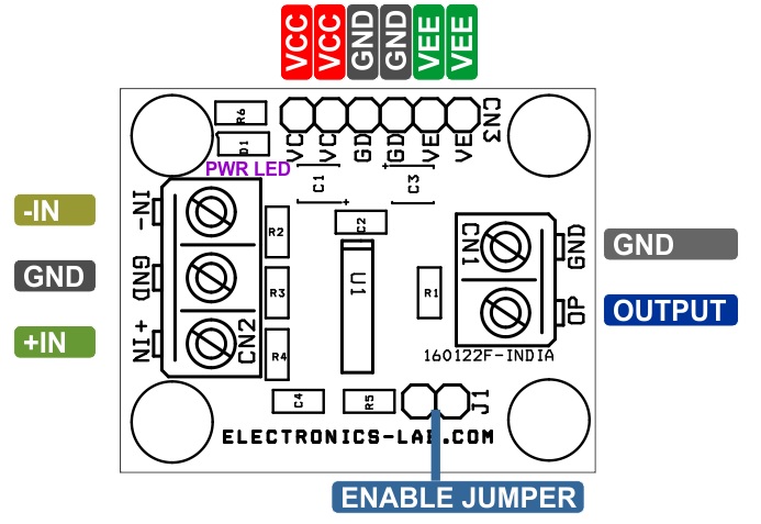
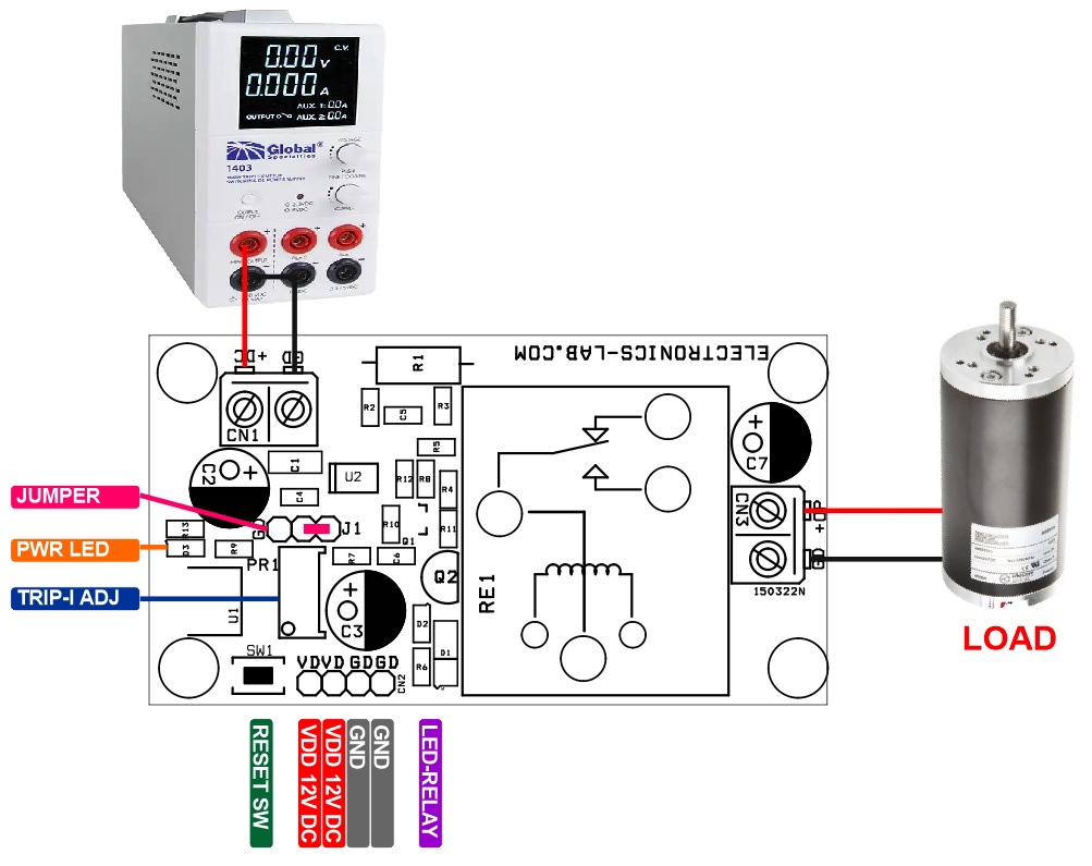
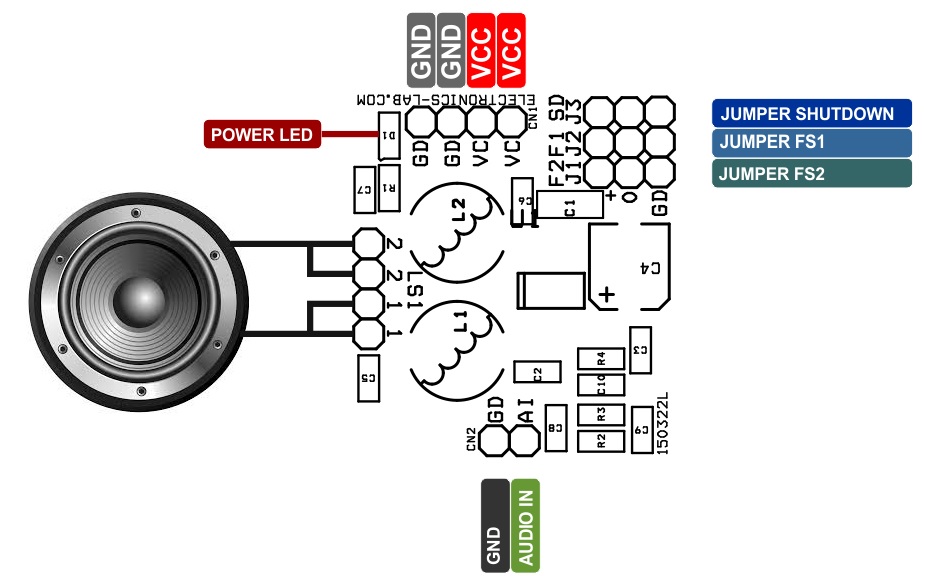
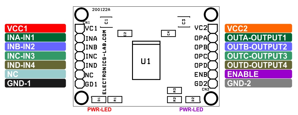
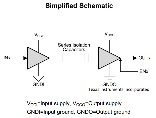
Connections
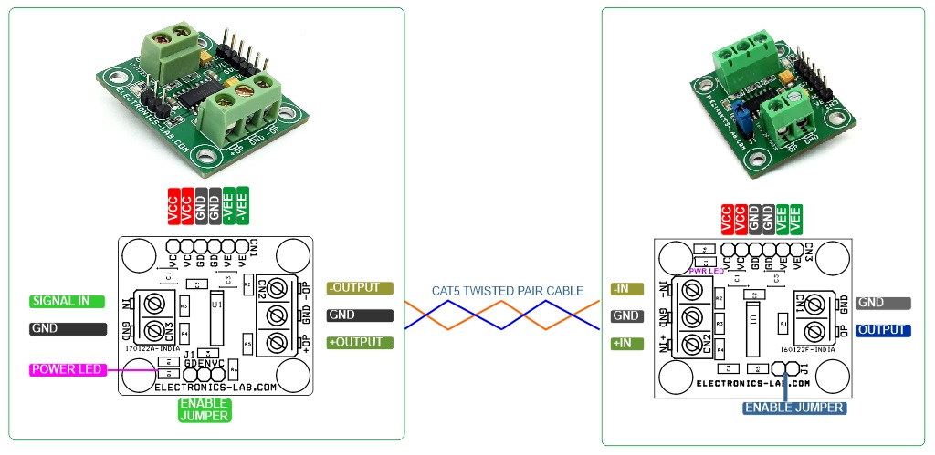
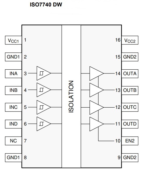
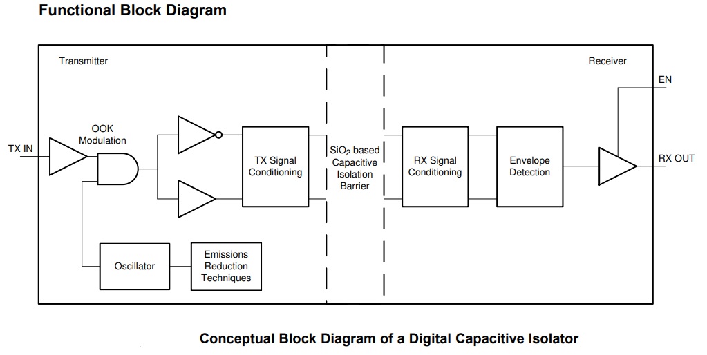
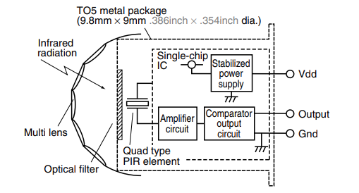
Block Diagram
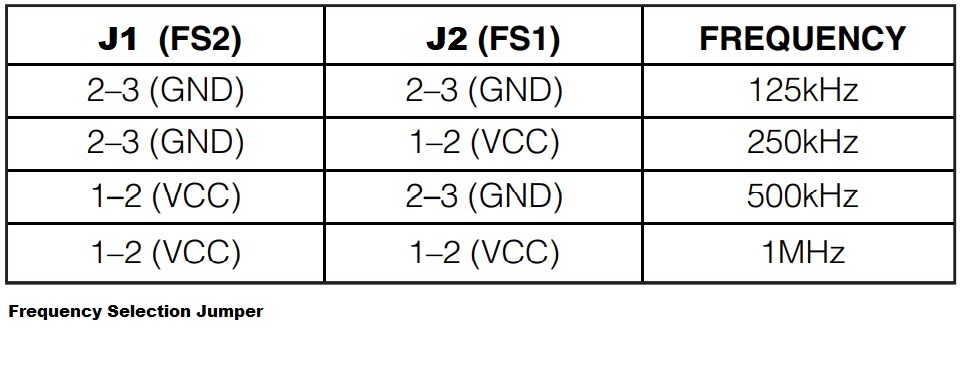
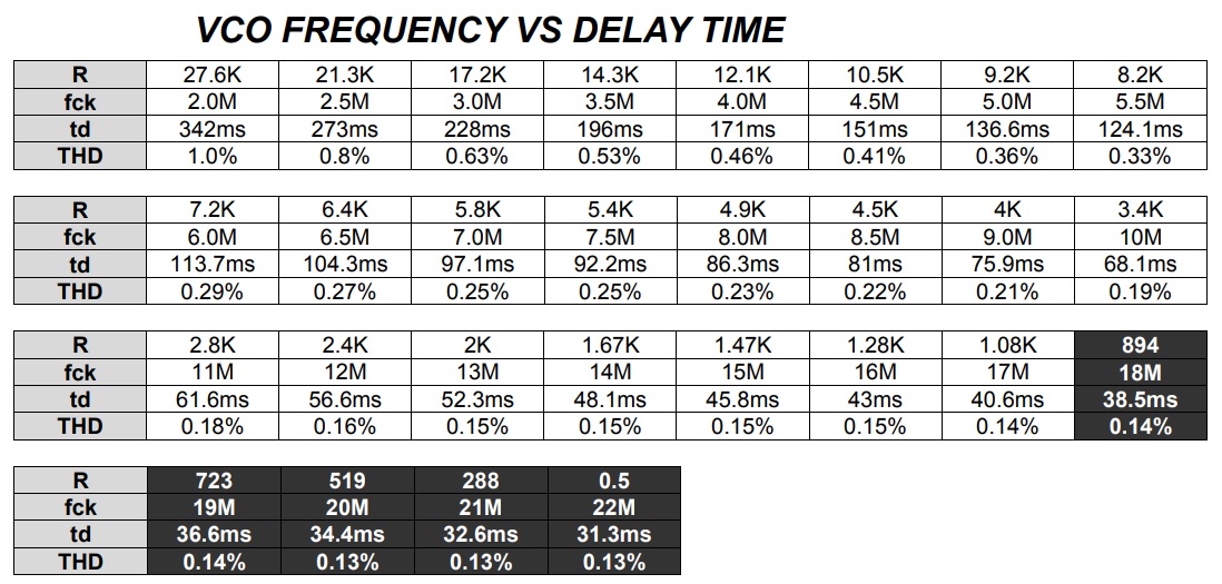
VCO Frequency Table
Gerber View
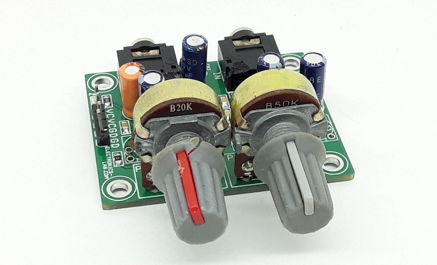
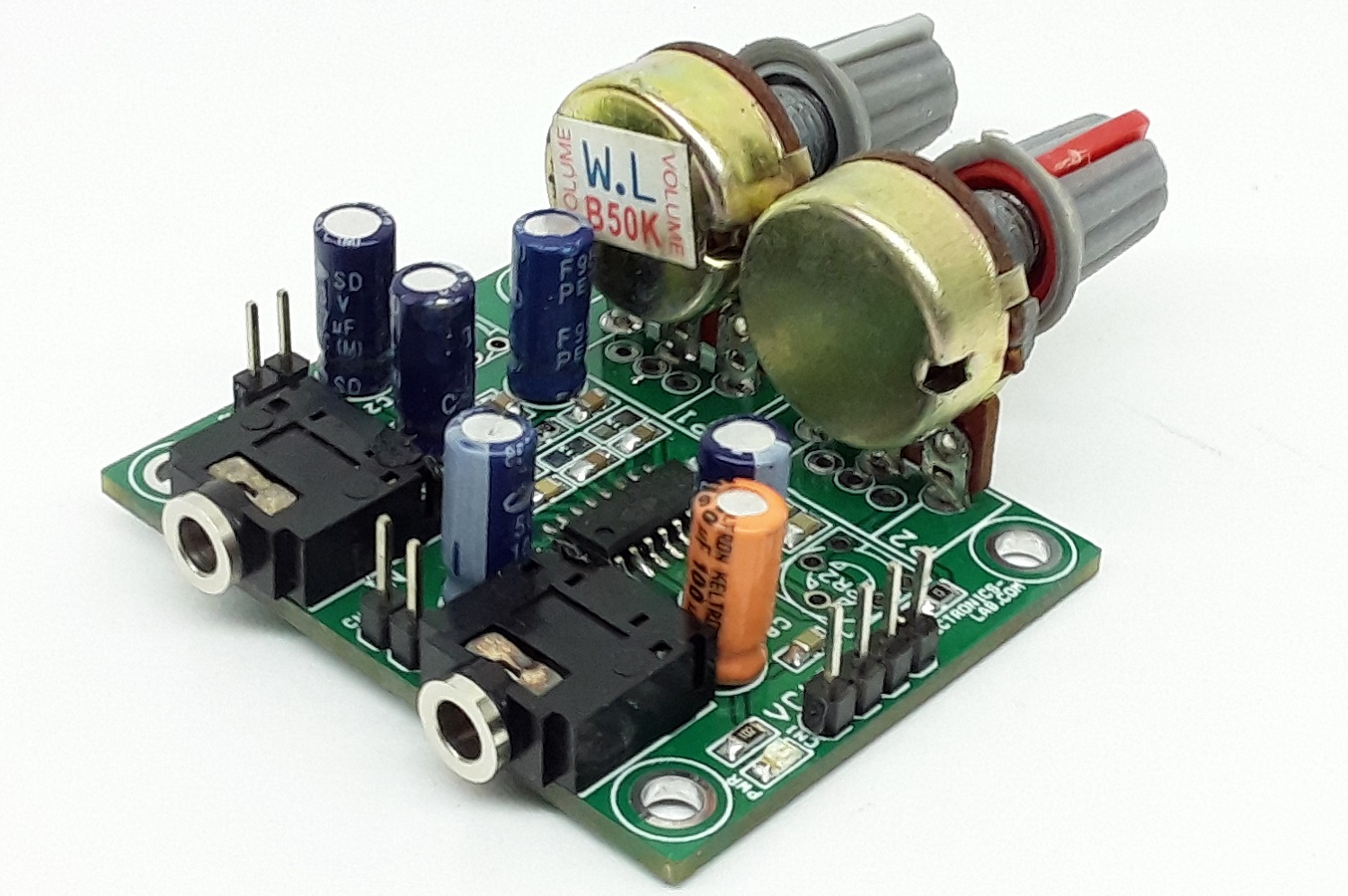
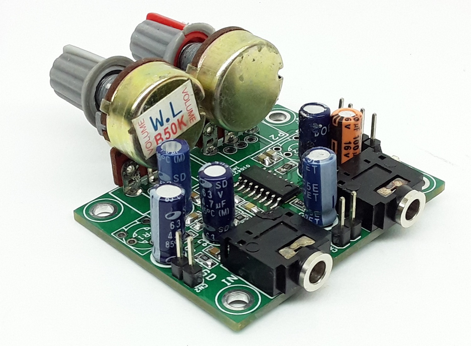
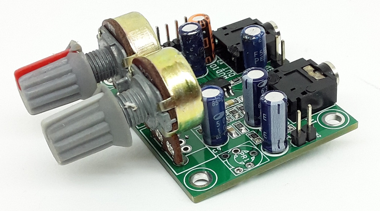
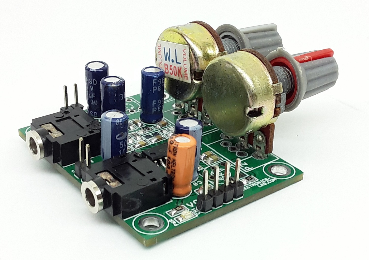
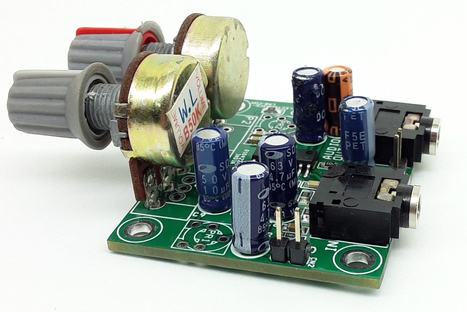
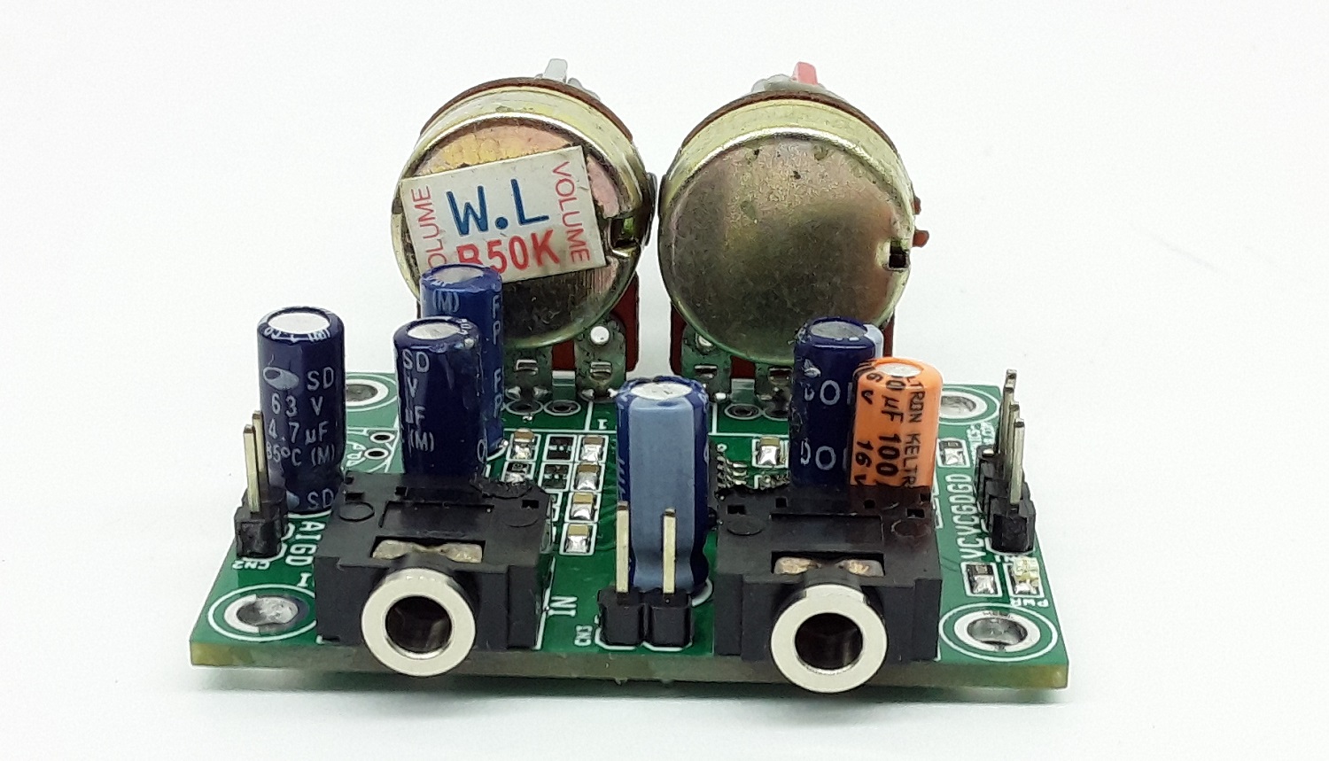
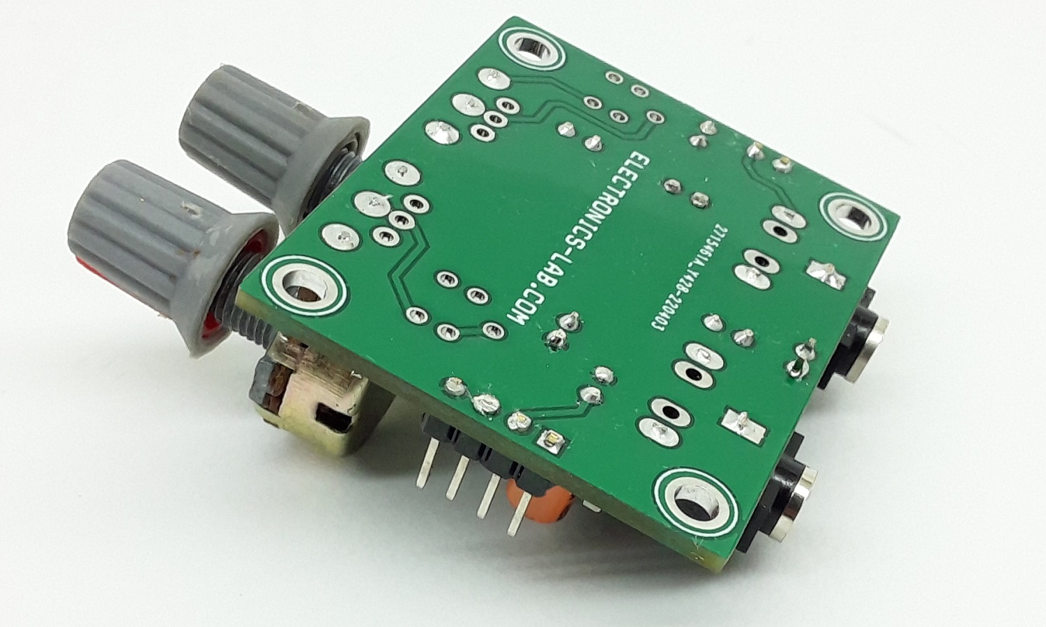
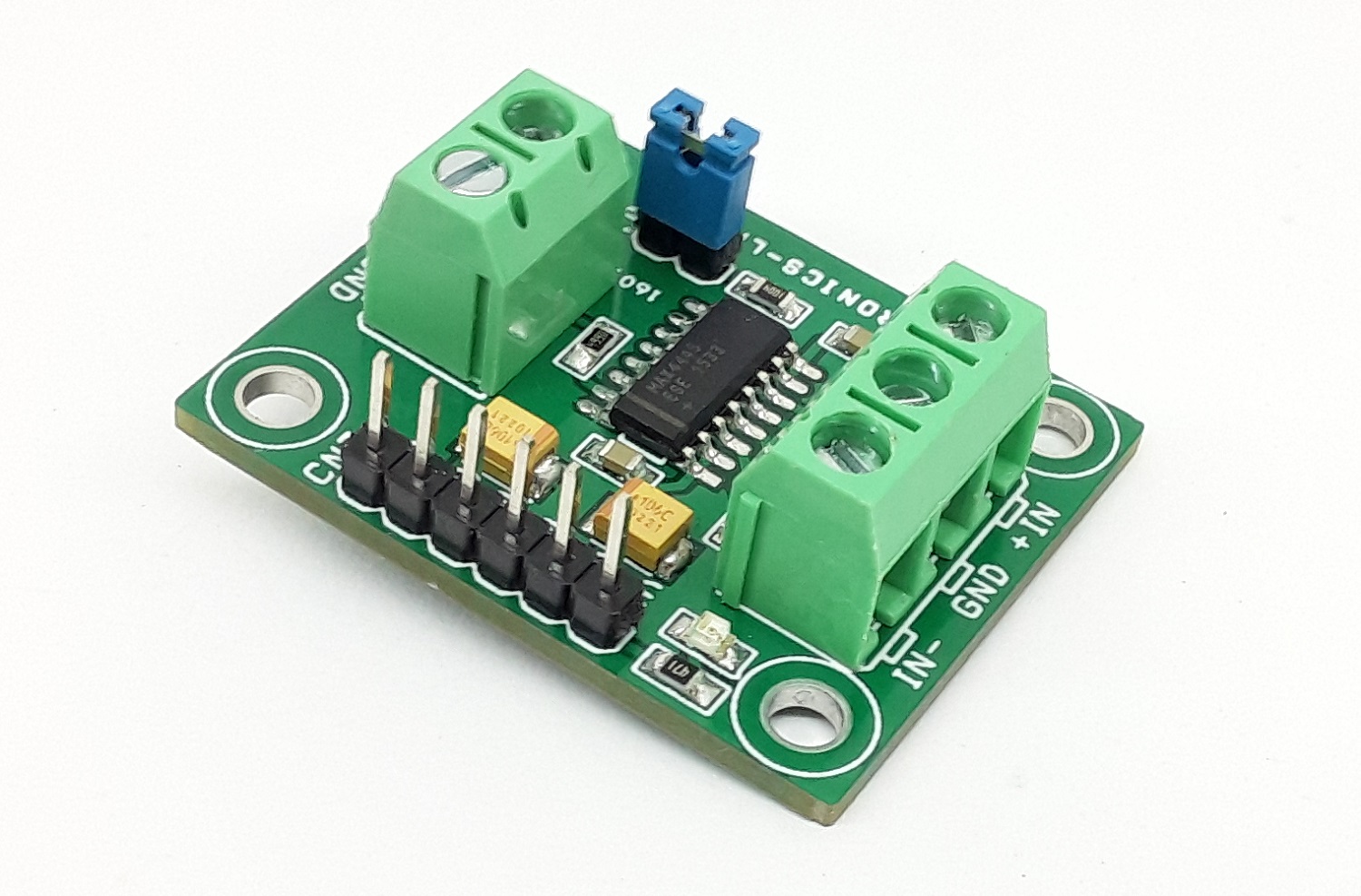
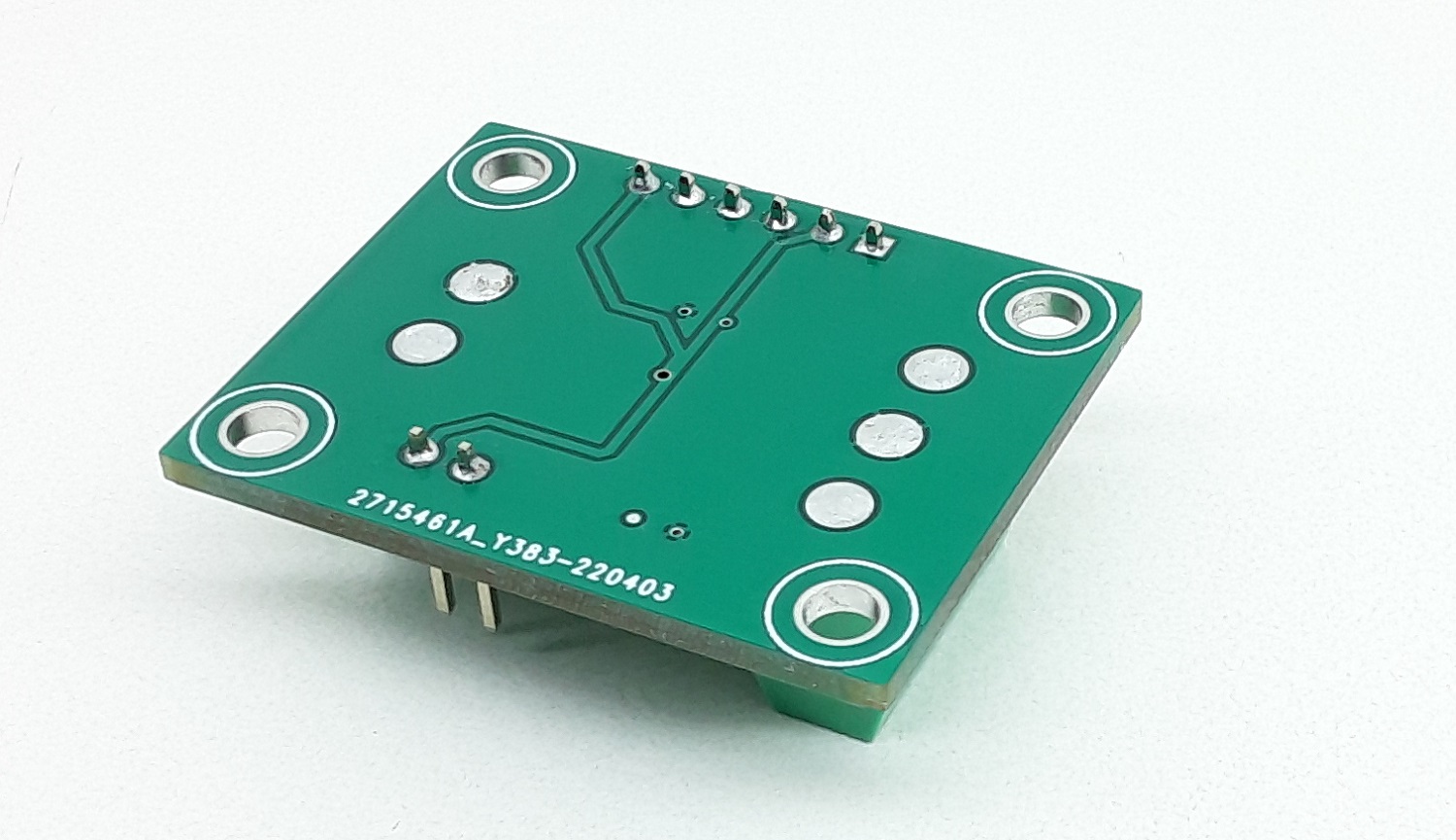
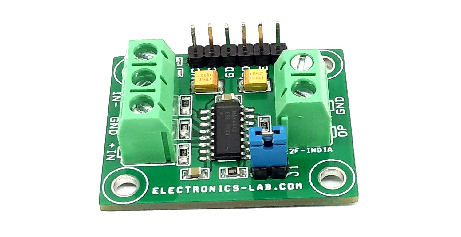
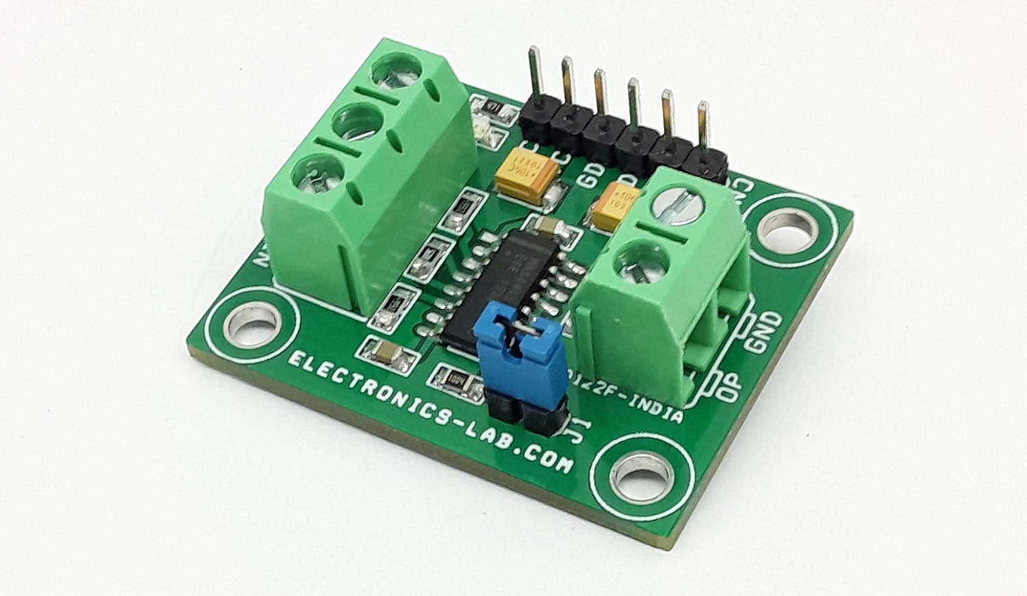
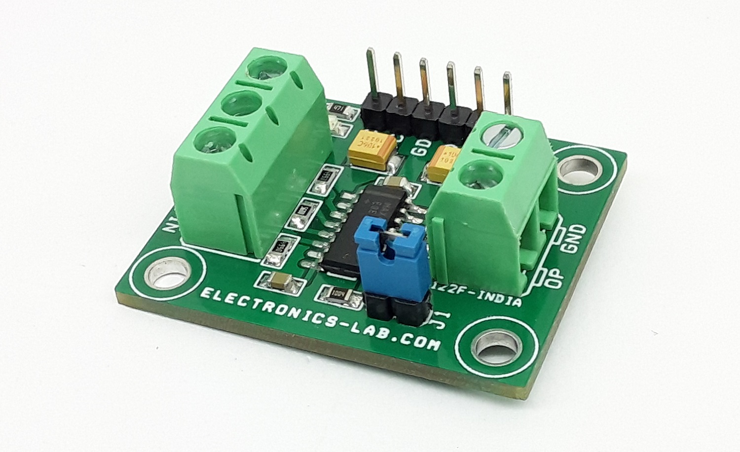
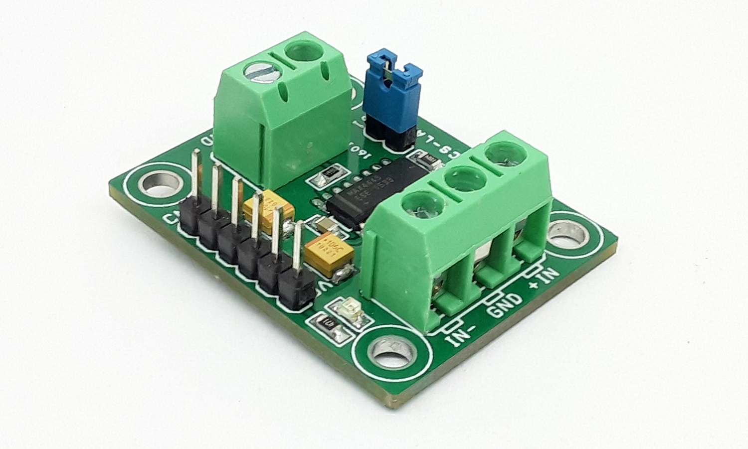
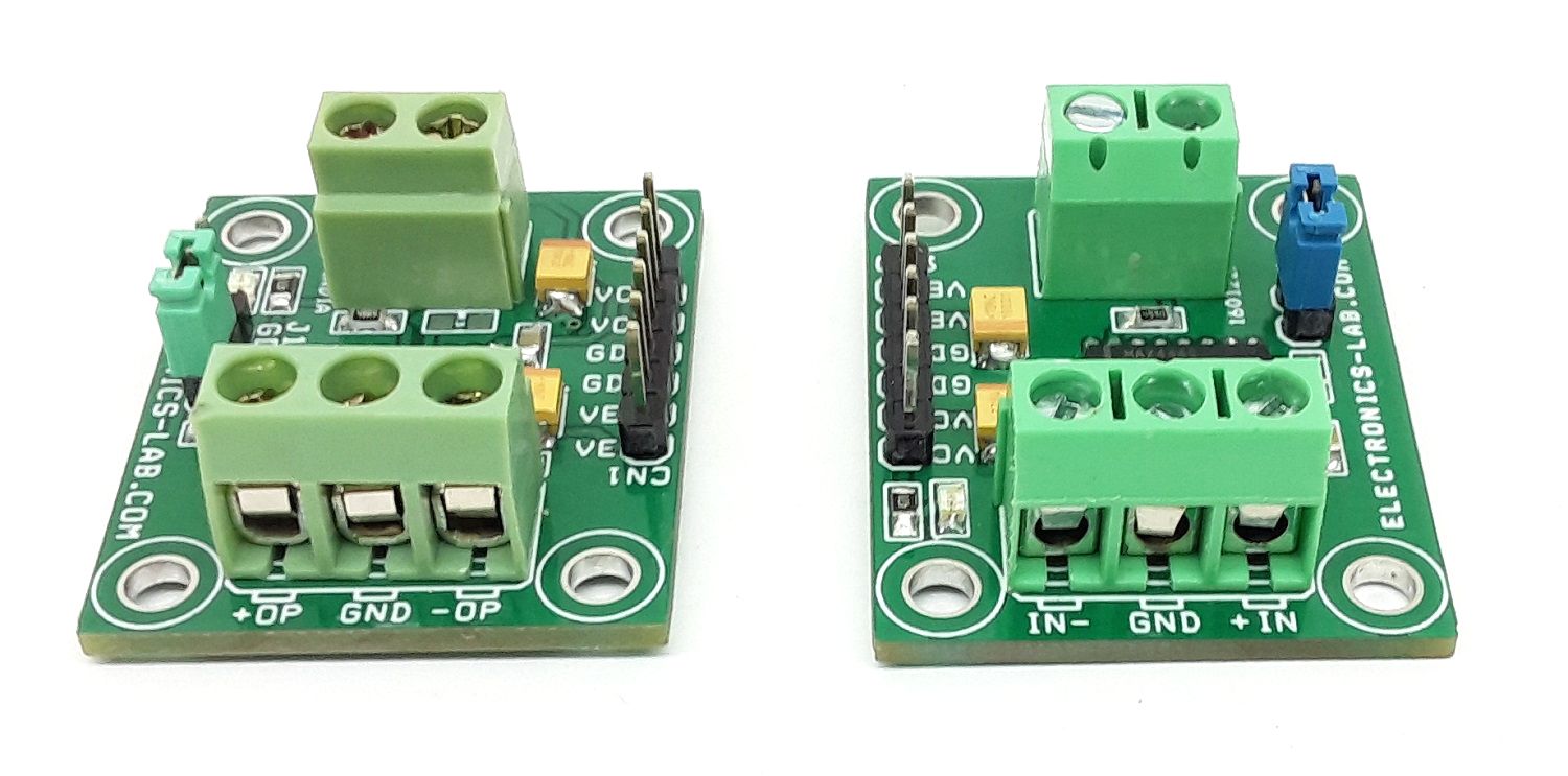
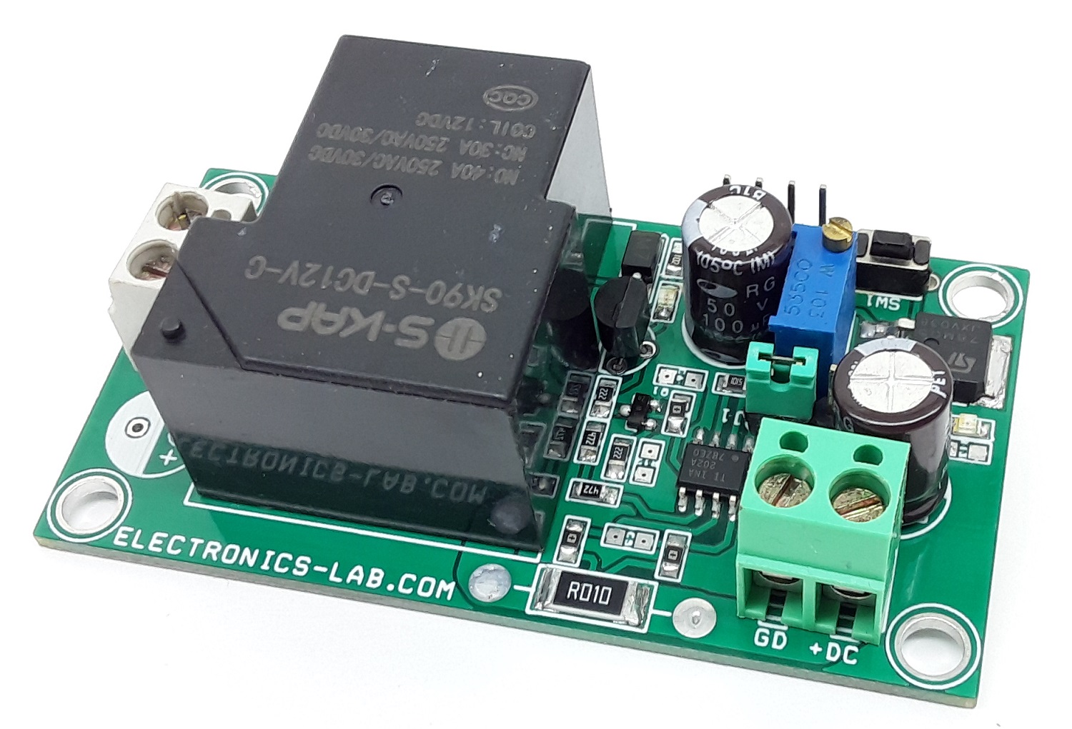
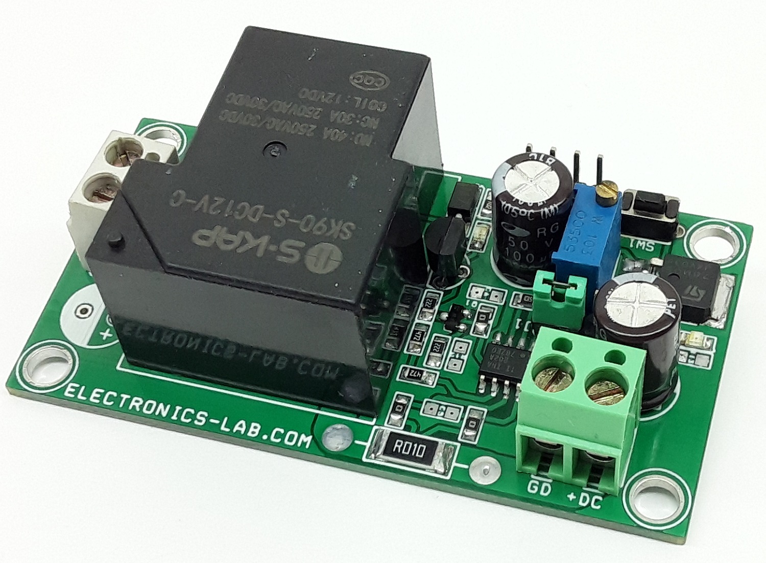
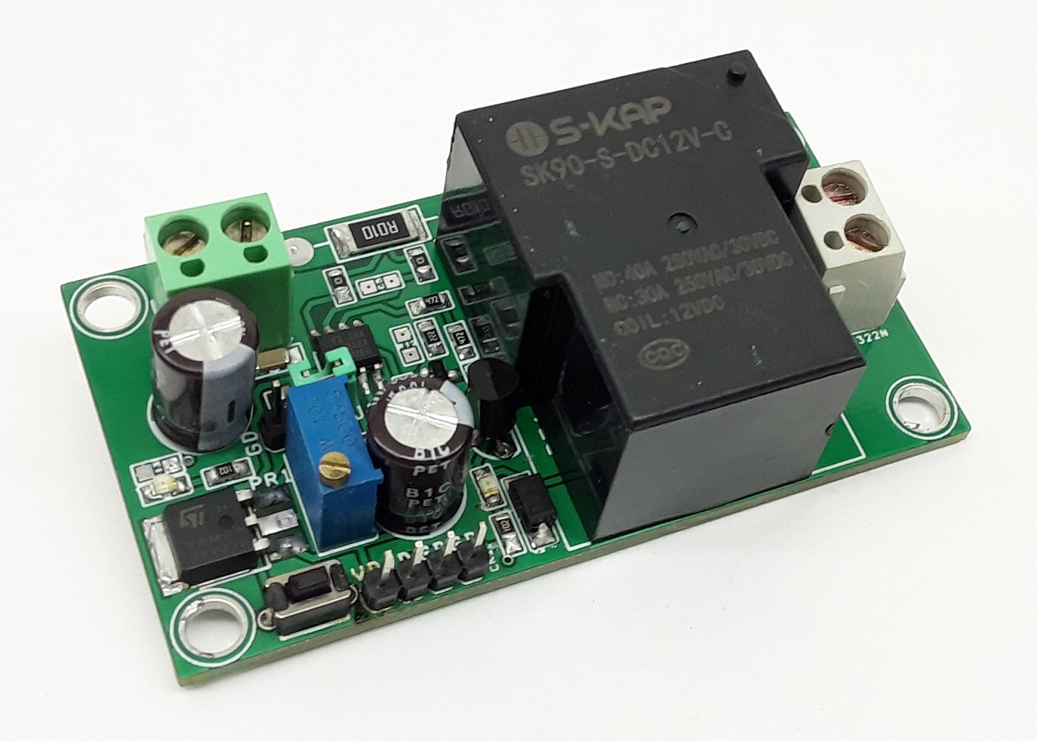
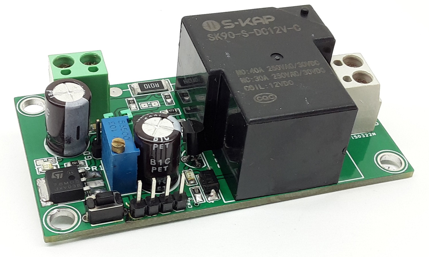
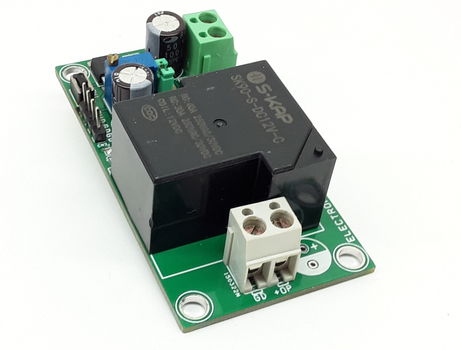
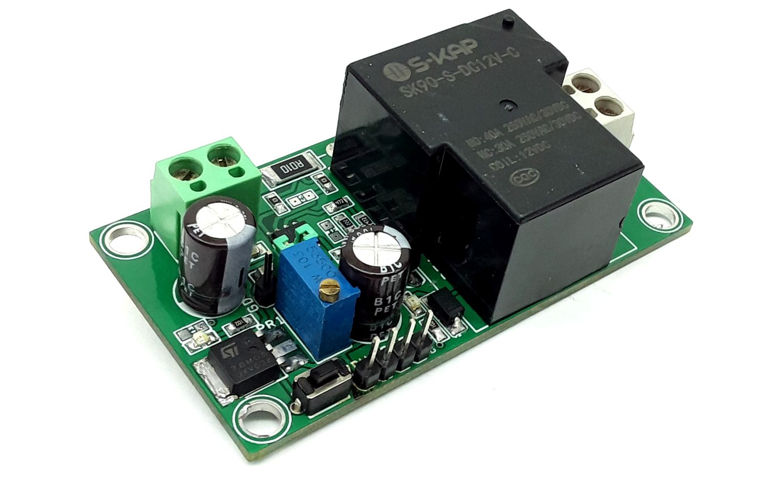
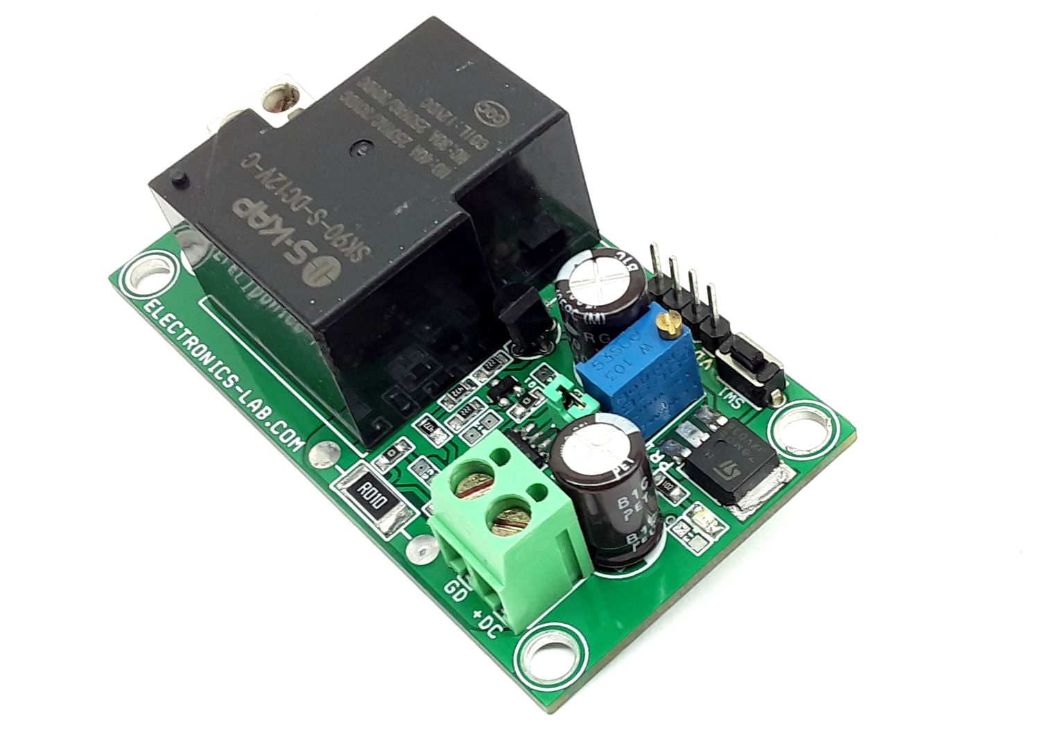
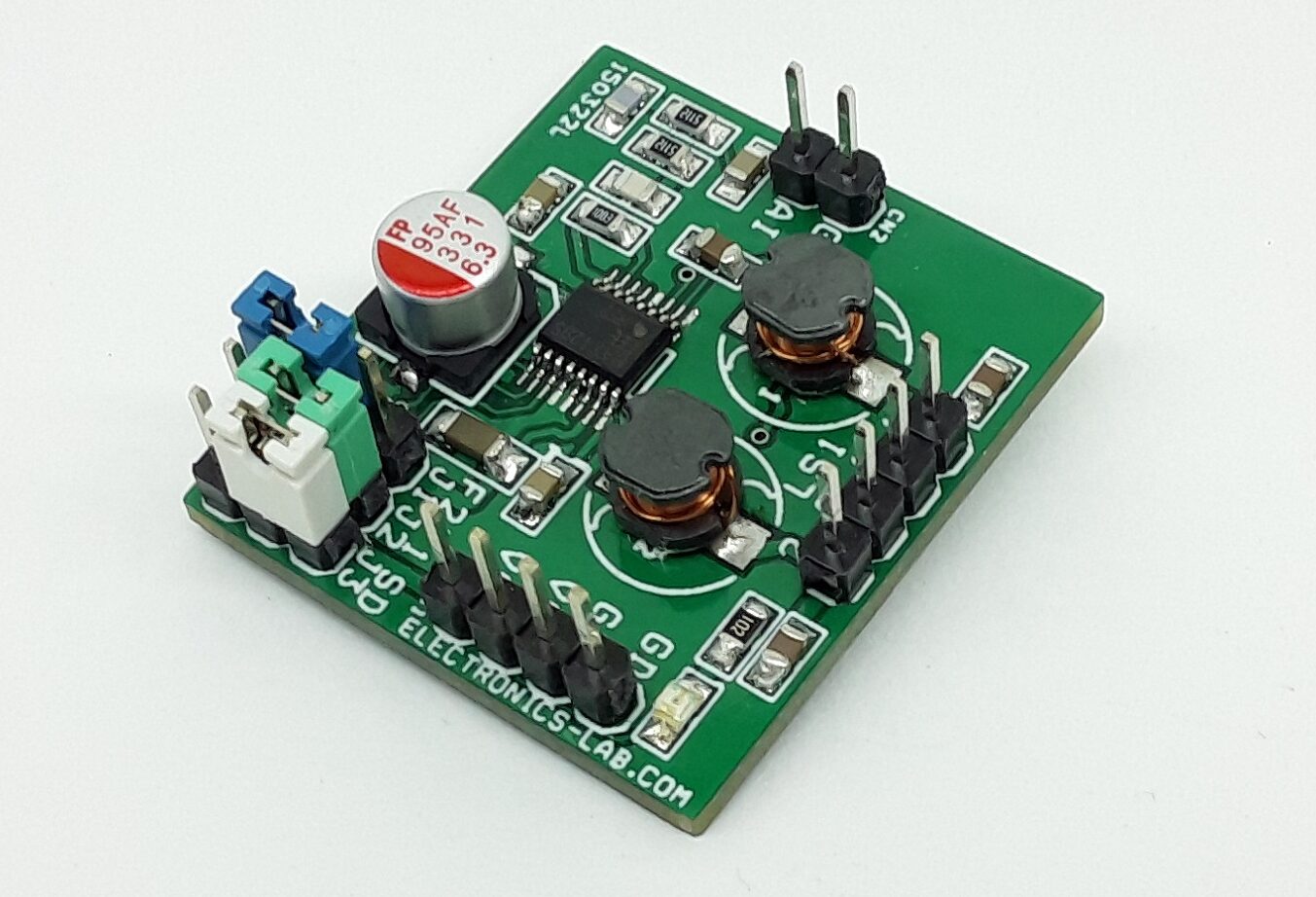
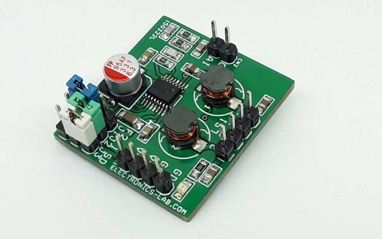
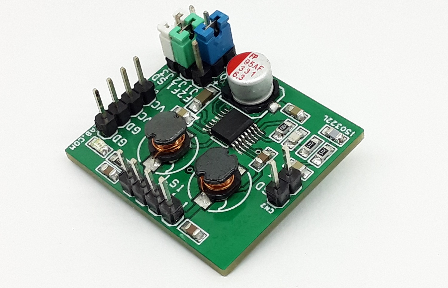
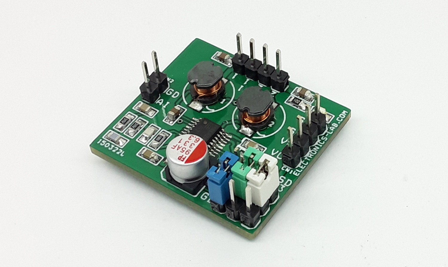
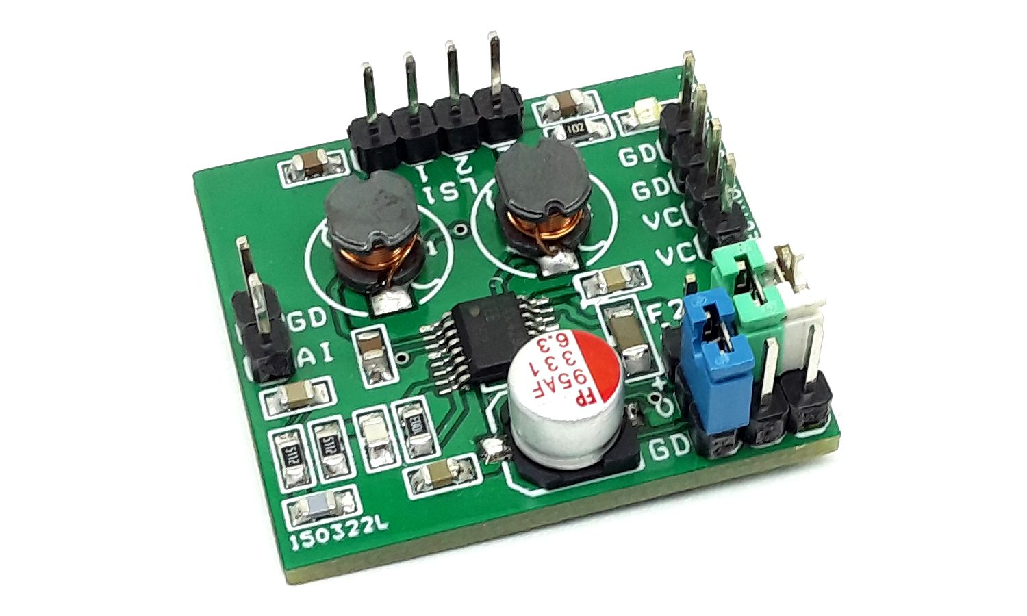
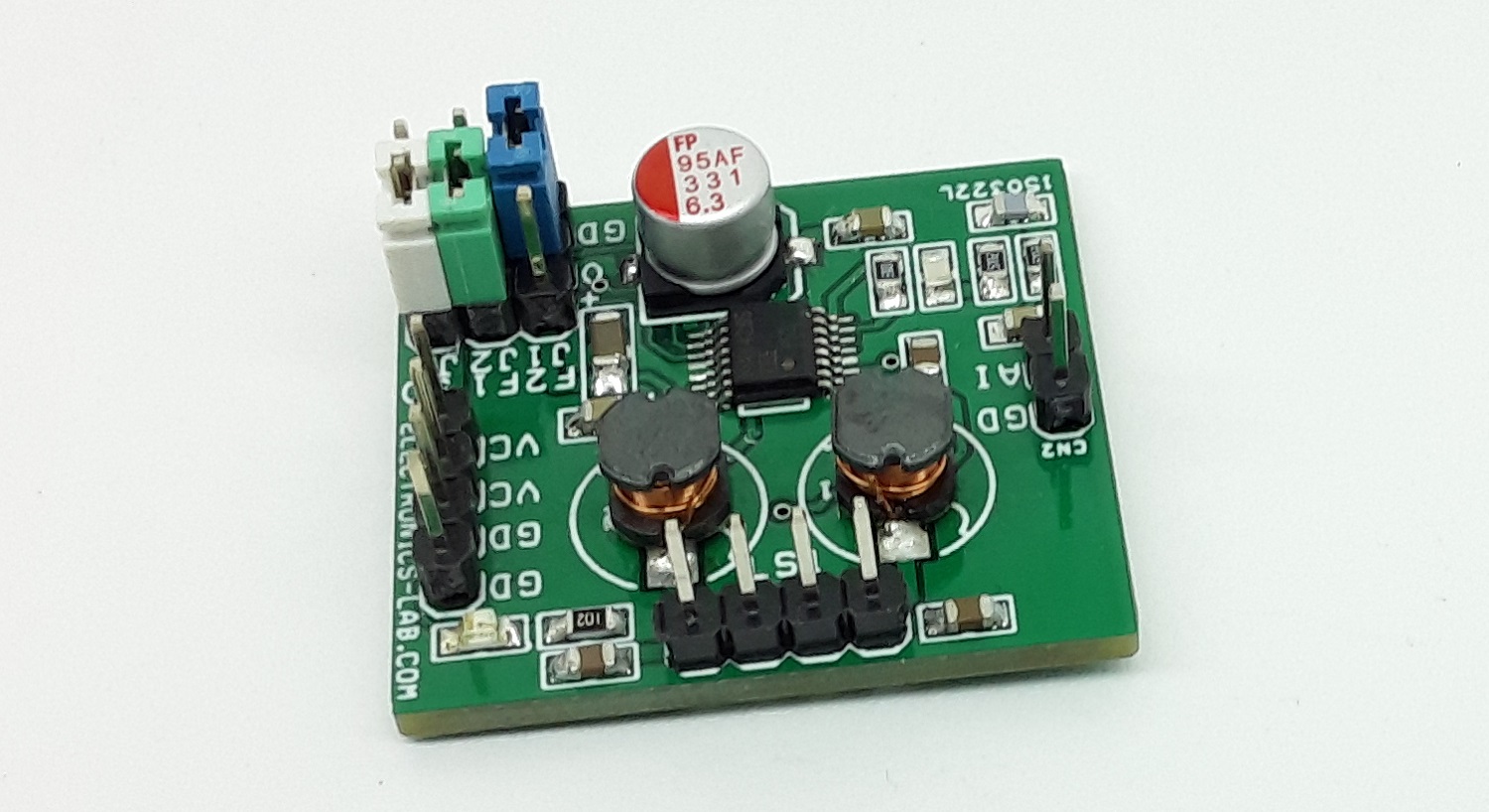
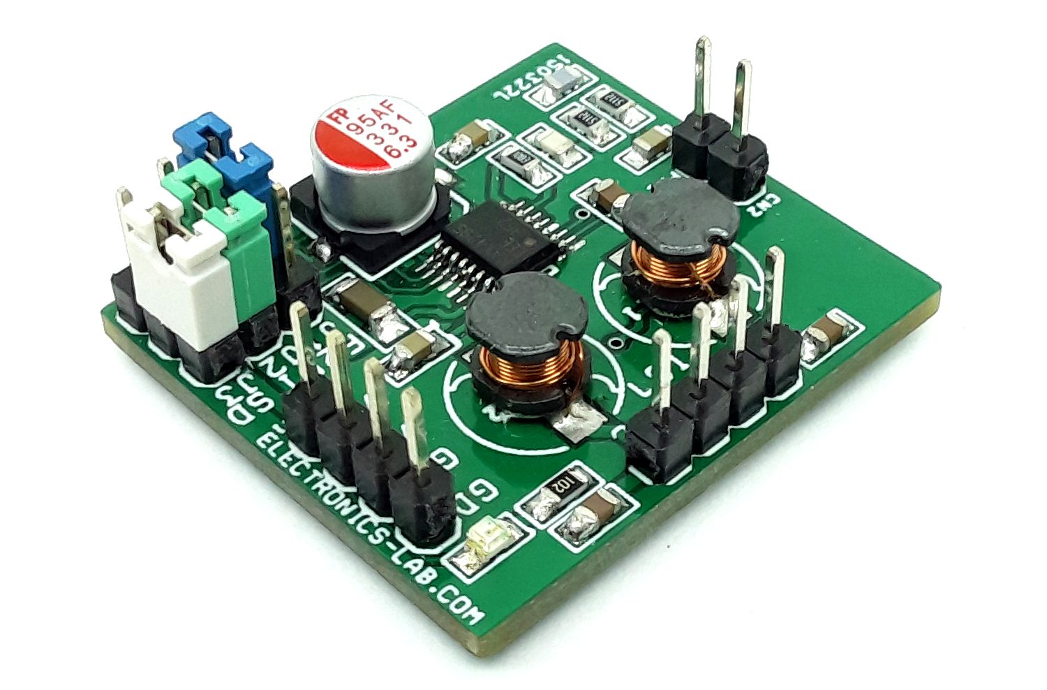
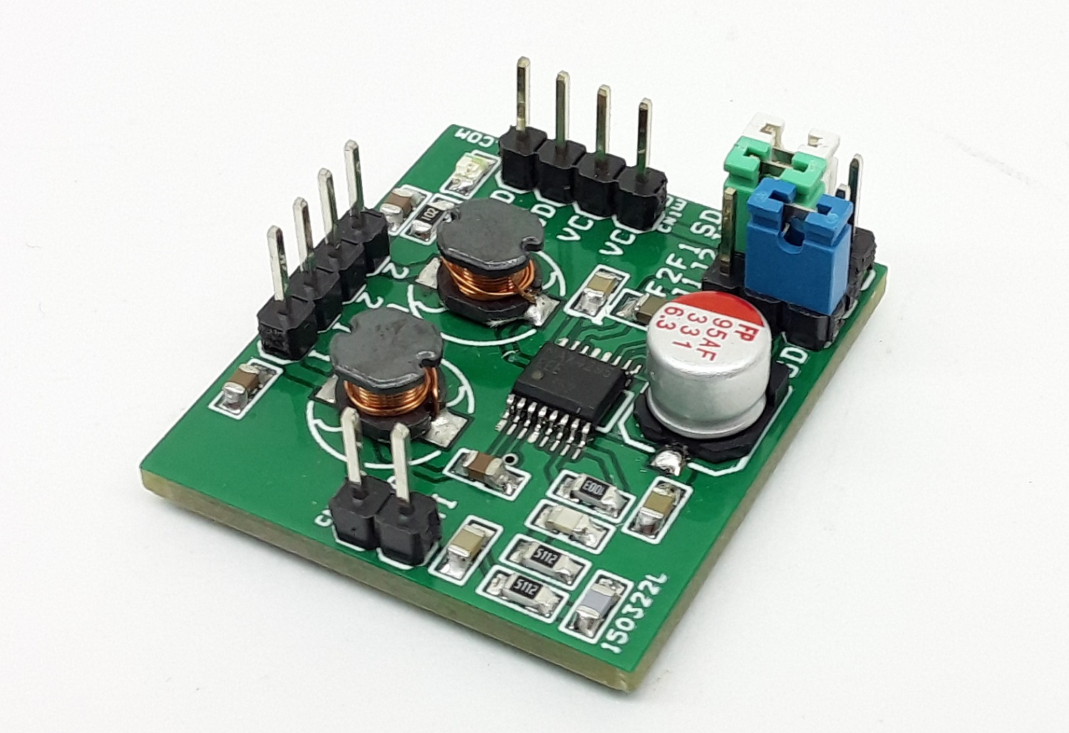
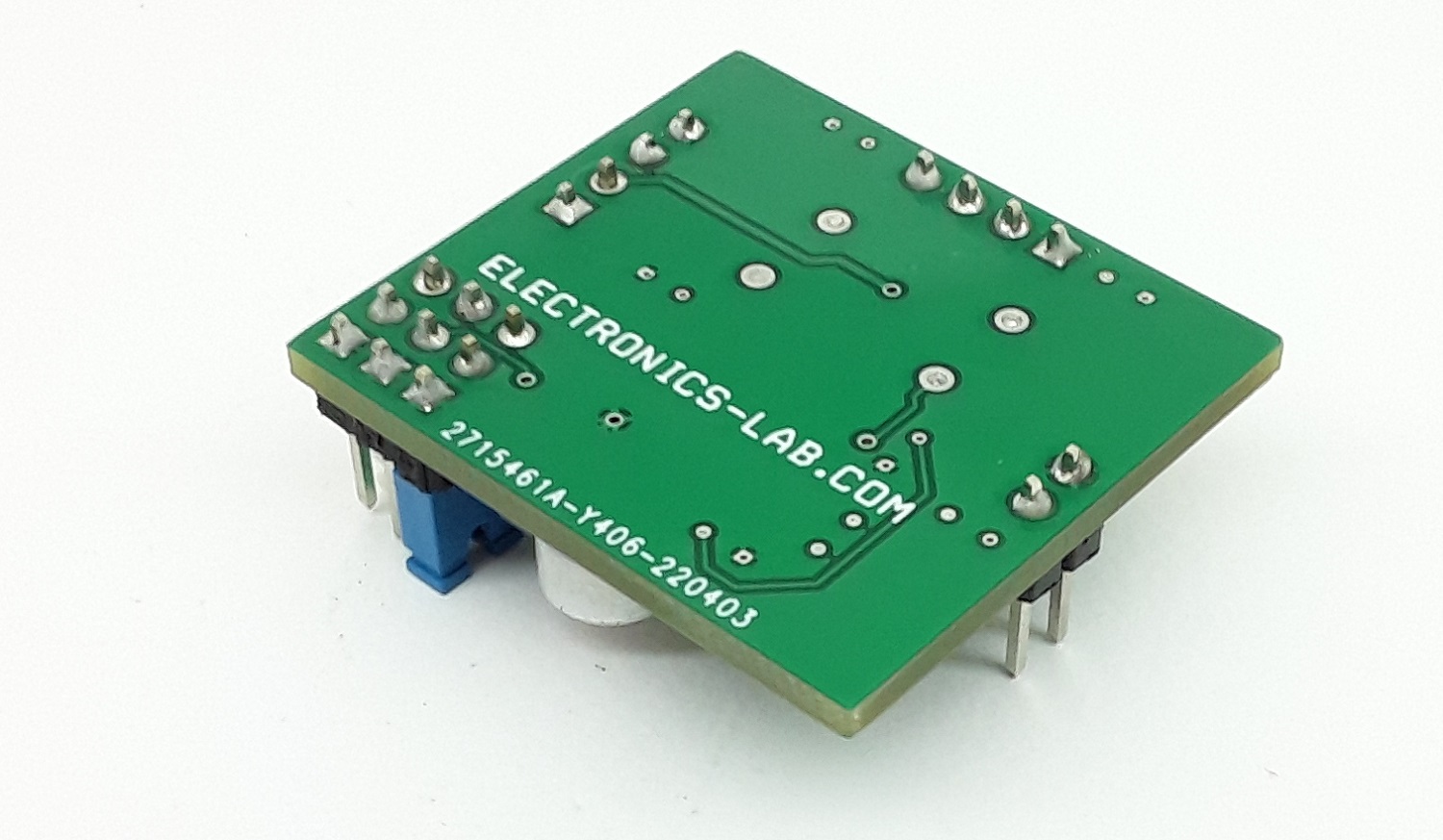
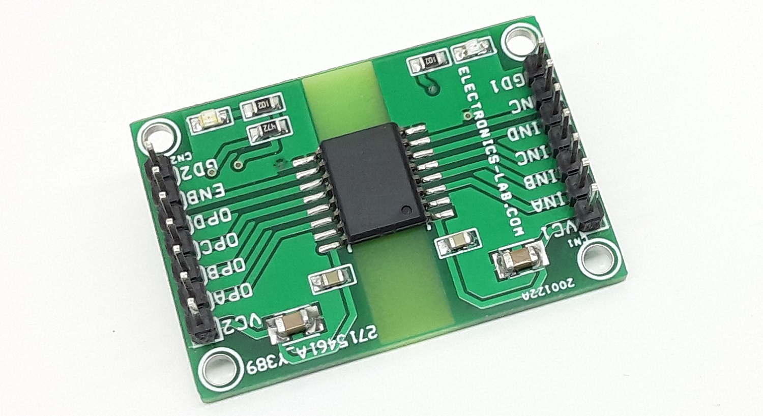
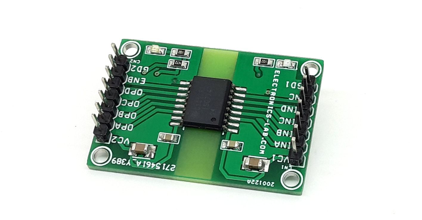
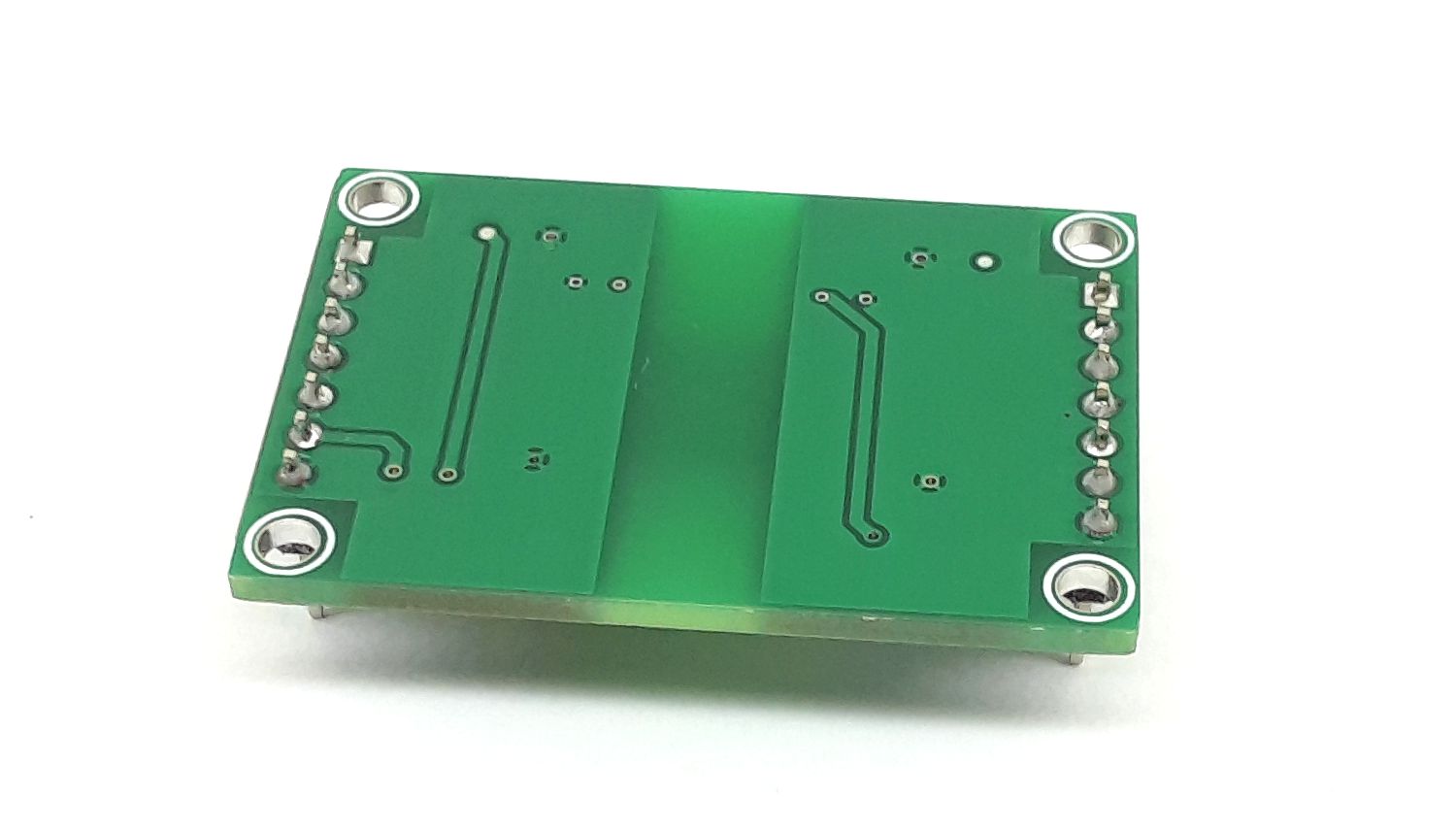
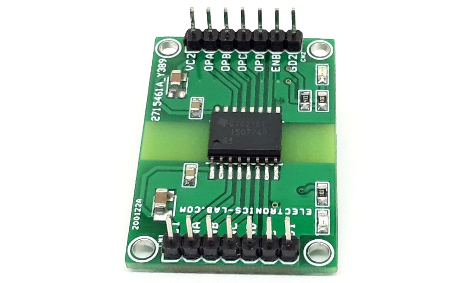
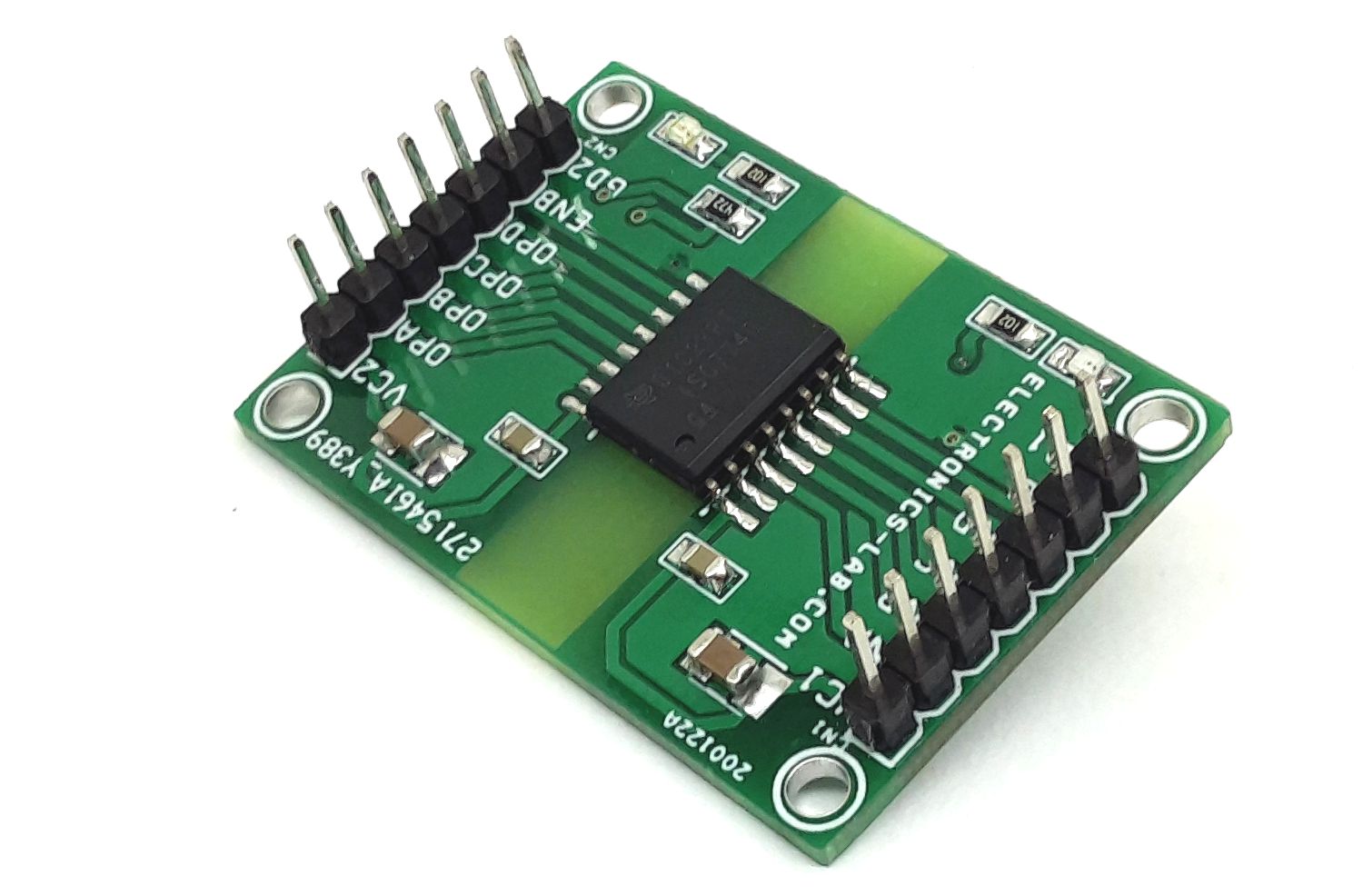
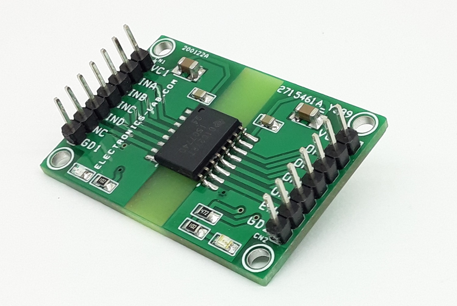
Photos