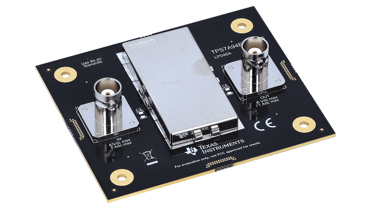
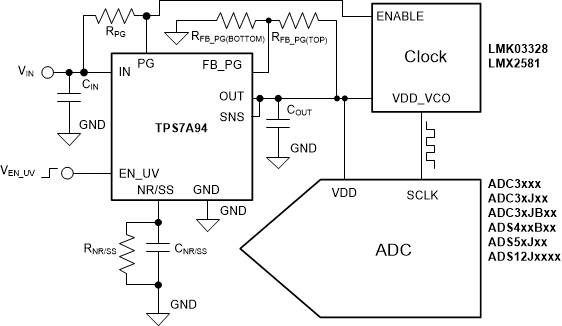
Recently Texas Instruments unveils Ultra-low Noise RF Voltage Regulator TPS7A94. This device is a low noise 0.46μVrms, Low Dropout (LDO) voltage Regulator. It can provide output current up to 1A with only 200mV of maximum dropout. It can operate with a minimum of 1.7V to maximum 5.7V input and gives a maximum output voltage 5.5V with a maximum current of 1A. In this device, we can adjust the current limit TPS7A94 allows programmable PG threshold, and precision enable.
TPS7A94 has high accuracy reference and wide bandwidth utility gain follower LDO, this device can be easily paralleled to achieve lower noise and high current output.
With its 1 percentage output voltage accuracy and soft start capabilities to reduce inrush current, this device is a good choice for powering sensitive analog low voltage devices such as VCOs (Voltage Control Oscillators), ADCs (Analog to Digital Converters), DACs (Digital to Analog Converters) and FPGAs (Field Programmable Gate Arrays).
This device Comes in WSON (10) Package and has 3.0 mm X 3.0 mm body size. For more information Product page.
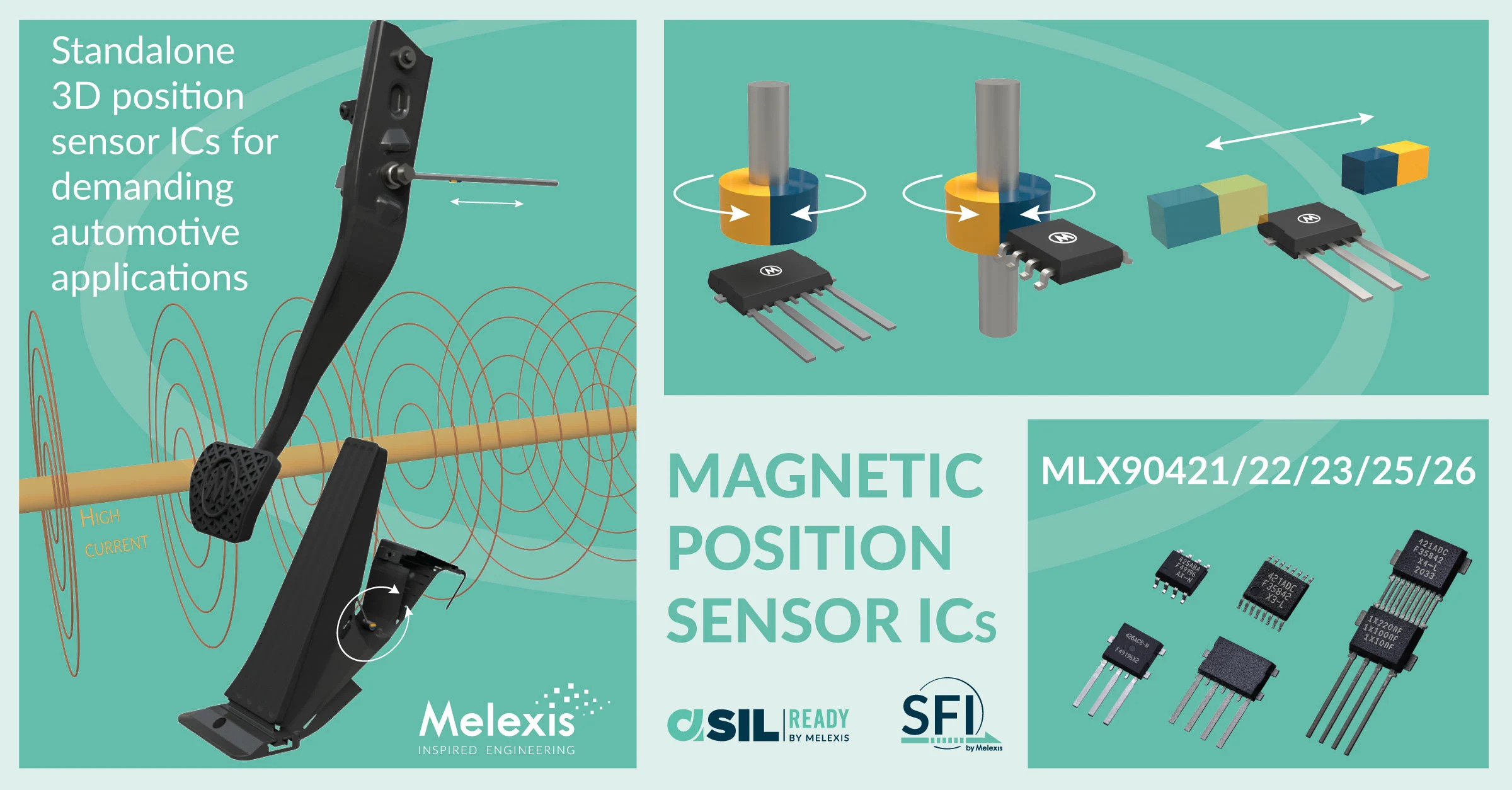
Melexis delivers a cost-optimized family of 3D magnetic position sensors with performance enhancements for automotive applications.
Melexis has expanded its portfolio of 3D magnetic position sensors with the introduction of the MLX9042x series. These sensors are designed for automotive applications that need to measure absolute position accurately in harsh and noisy environments over an extended temperature range. These include powertrain actuators, transmission sensors, pedal position sensors, and chassis sensors. The sensors also can be used in industrial applications.
Building on the MLX9036x product family, the new MLX9042x portfolio delivers a cost-optimized series with all the core features, said the company, along with functional safety and EMC enhancements, an extended improved operating temperature range, and improved stray magnetic field capabilities.
Based on the company’s Triaxis Hall sensor technology, the MLX9042x devices all feature analog signal conditioning, data conversion and signal processing, as well as output stage drivers.
The initial devices in this series are the following:
MLX90421: rotary and linear use, with analog or PWM output
MLX90423: linear stray field immune with either analog, PWM, or SENT output
MLX90425: rotary 360° stray field immunity with analog or PWM output
MLX90426: rotary 360° stray field immunity with SENT output
These devices are ASIL B ready (per ISO 26262), enabling the design of functionally safe actuators and sensors for safe vehicle operation. Dual-die versions are available, in addition to the single-die chips, for applications that require higher levels of safety and availability. The MLX9042x devices offer similar performance as the products in the MLX9037x family to ensure first-time-right EMC testing, said the company, requiring only one test cycle. The high absolute maximum ratings (AMR), including reverse polarity, reduce the number of quality incidents due to electrical overstress, according to the company.
The 3D magnetic position sensors feature an extended temperature range of -40°C to 160°C. This allows the devices to operate in hot environments, including engine compartments or where start-stop conditions cause increased heat soaks.
The MLX90423, MLX90425 and MLX90426 sensors also offer improved stray magnetic field capabilities. These devices are capable of rejecting stray magnetic fields up to 5 mT or 4000 A/m in rotary and linear position sensing applications.
The AEC-Q100-qualified MLX9042x devices can be supplied in SMD packages or in SMP-3 and SMP-4 PCB-less packages (where the sensor and EMC capacitors are integrated into a single mold). Samples are available for the MLX90421/22 in SOIC-8/TSSOP-16/DMP-4/SMP-3/SMP-4 packages and the MLX90425/26 in SOIC-8/SMP-3 packages (more to come later). The MLX90423 will be available for order in November 2022. The company expects to add other products in the future.
Silanna Semiconductor claims the industry’s first buck converter with intelligent adaptive power sharing for multi-port fast chargers.
Silanna Semiconductor has claimed the first buck converter power IC to feature intelligent adaptive power sharing. The SZPL3002A buck converter with a built-in USB PD/FC port controller will significantly reduce component count to implement 65-W fast charger and adapter applications with up to four ports, said the company.
The SZPL3002A combines a high-efficiency synchronous buck converter and an advanced port controller in a QFN package measuring 5 × 5 mm. It is built on the company’s wide-voltage, high-frequency point-of-load DC/DC converter technology with higher than 98% efficiency.
The integrated port controller supports USB PD V3.0 Type C interfaces and QC2.0/3.0/4.0/5.0 support for Type A/C connections. The controller’s job is to ensure that the port power adapts to the device’s requirements, delivering power sharing and port power re-balancing functionality across two, three or four ports.
High-Efficiency (>98%) Synchronous Buck Converter
Selectable Switching Frequency: 667kHz to 2MHz
3.3V to 21V Output at 3.25A (covers PD + PPS)
7V to 27V Input
41mohms upper FET, 38mohms lower FET
Selectable power saving mode
Selectable soft start time
Full protection features such as OCP, OVP, OTP
I2C bus for communication
All surface mount components solution
Available in small QFN 5 mm X 5 mm thermally enhanced package
Integrated with Most Advanced Port Controller
Provide a complete USB Port Power supply
Full Support for USB PD V3.0 – Type C
QC2.0/3.0/4.0/5.0 Support for Type A/C Ports
USB-IF certified
Calculated, Adaptive Power Sharing
Power Sharing Across 2, 3 or 4 Ports
Includes Port Power Re-Balancing
Power Throttling at Elevated Temperature
Integrated VCONN Power Supply
5 Power Profiles (Resistor-Selectable)
The power IC is the first to use an integrated USB-PD controller, microcontroller, and VCONN cable communications protocol in a DC/DC buck converter, according to the company.
Thanks to the five selectable pre-loaded power contract configurations, designs can use a single ZPL3002A across multiple product designs.
“Power re-balancing allocates under-used power on previously connected ports, while protective power throttling automatically reduces current when temperature thresholds are reached,” said Silanna.
Hubie Noto, director of product marketing, Silanna Semiconductor explained:
“The SZPL3002A offers one fully programmable contract set plus four pre-programmed sets that are chosen with an external resistor value,” said “Traditional charger PD ports offer a selection of fixed contracts to a device based on available power. These are programmed into the port controller and are based on various voltage and current levels a device might use when connecting. Each port has different power contracts for different power.”
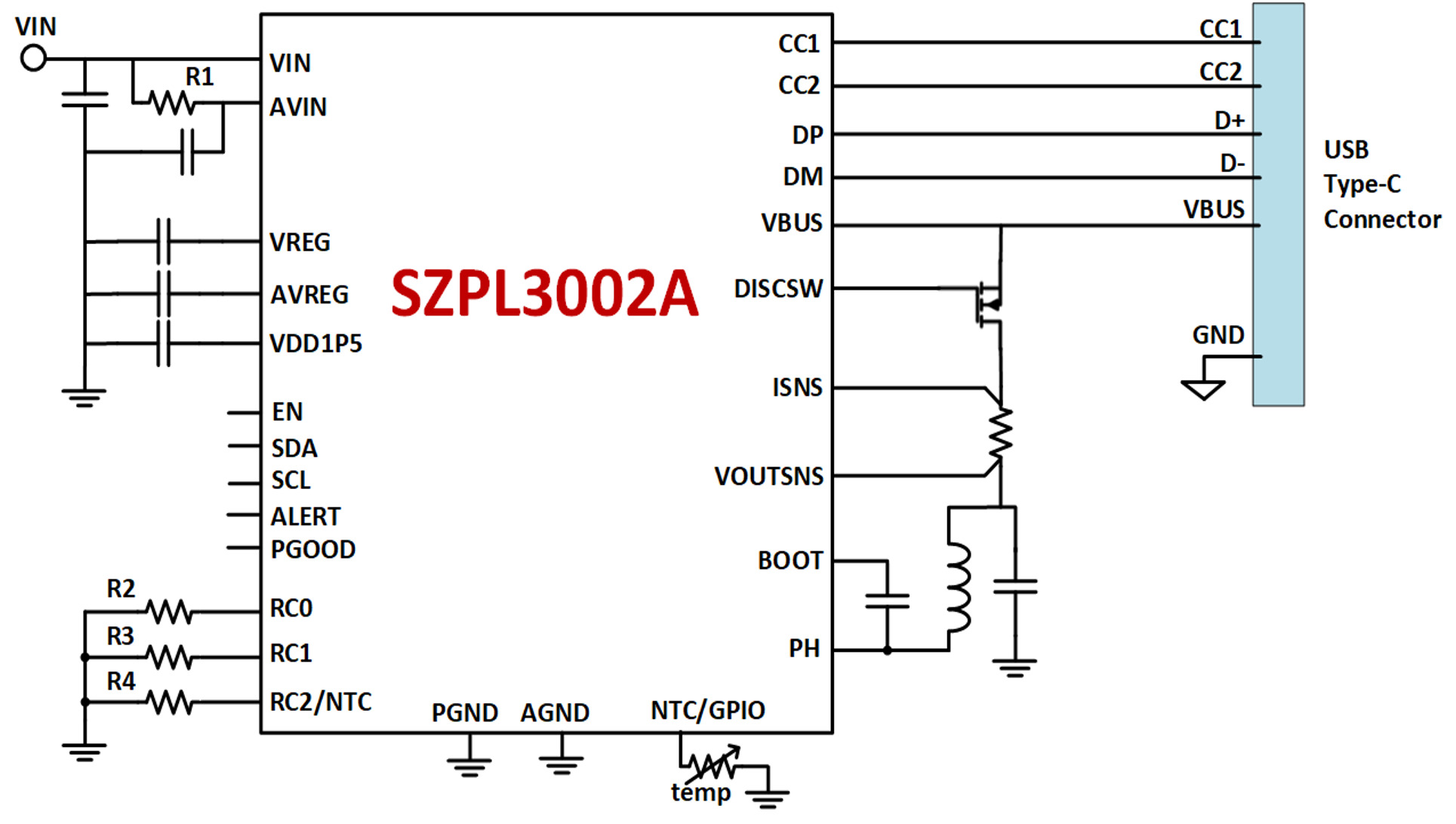
The buck converter offers a selectable switching frequency from 667 kHz to 2 MHz and a 7-V to 27-V input range. The device provides a 3.3-V to 21-V output at 3.25A (which covers PD + PPS). The RDS(on) of the upper FET is 41 mΩ and 38 mΩ for the lower FET. Other features include a selectable power save mode, selectable soft start time, and protection features such as overcurrent protection (OCP), overvoltage protection (OVP), and overtemperature protection (OTP). It comes with an I2C communication interface.
Application Diagram
Key accounts are sampling the SZPL3002A buck converter. It will be released to the general industry in the second half of 2022.
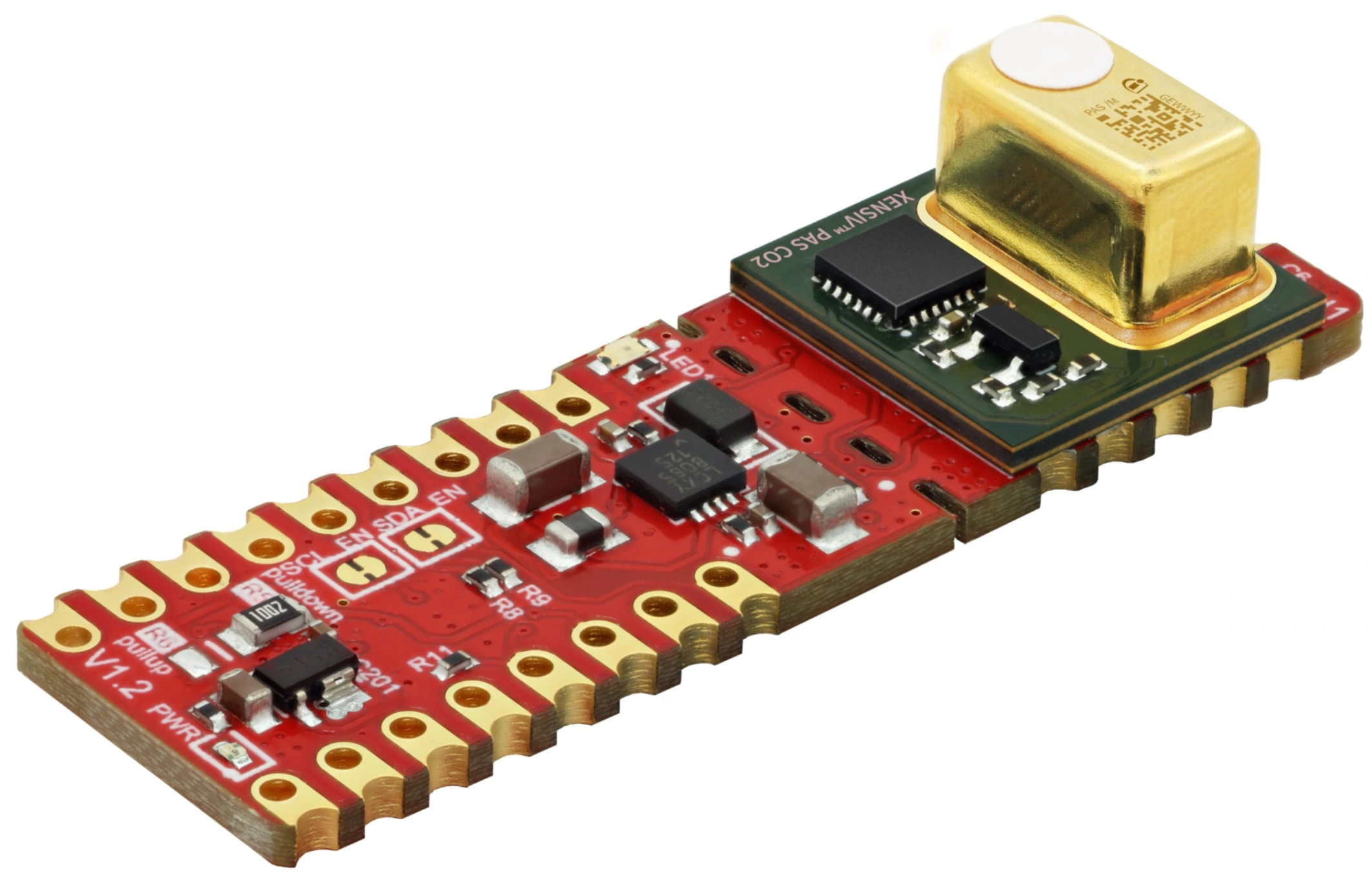
Infineon launches its XENSIV PAS CO2 Shield2Go evaluation board for CO2 monitoring, which supports both Arduino and Raspberry Pi development.
Infineon Technologies AG has launched the XENSIV PAS CO2 Shield2Go board for carbon dioxide (CO2) measurement. The evaluation board is suited for both air quality monitoring and demand-controlled ventilation for energy savings.
The board is part of the Infineon Shield2Go portfolio featuring sensors, microcontrollers, and security ICs that can be combined as part of an integrated prototyping concept. The new board allows developers to design a custom application with Arduino and Raspberry PI and comes with a ready-to-use Arduino library.
The XENSIV PAS CO2 Shield2Go board includes a DC/DC boost converter that supplies the sensor with the required 12-V power supply.
“In that way a 5-V supply, for instance via USB provided by a microcontroller board, is sufficient and allows prototyping without the need for an external 12-V power supply,” said Infineon.
Adapters from Shield2Go to the common prototyping form factors for Arduino Uno and Raspberry PI’s 40-pin interface are available to support quick start-up. All boards provide solderless connectors, allowing designers to stack the boards instead of soldering them.
The board also features the XENSIV PAS CO2 sensor with a small form factor, measuring 14 × 13.8 × 7.5 mm3 . The sensor offers high accuracy in the ppm range (±30 ppm ± 3 percent of reading), enabling it to meet the most stringent air quality regulations & standards, said Infineon. Other features include advanced algorithms for compensation and self-calibration, a variety of interfaces such as UART, I 2C, and PWM interfaces, as well as various configuration options, including sampling rate and baseline calibration.
The XENSIV PAS CO2 Shield2Go Board can be ordered now. Software libraries and examples for Arduino as well as a generic C++ library offering a high-level API for the board are available at https://github.com/Infineon
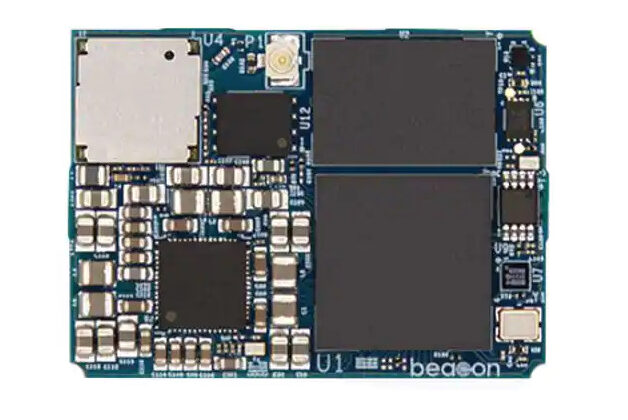
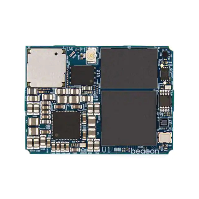
Beacon EmbeddedWorks’ wireless SoM features NXP’s i.MX 8M mini processor and Wi-Fi 5 and Bluetooth® 4.2 connectivity
Beacon EmbeddedWorks’ i.MX 8M Mini/Nano system-on modules (SoMs) can help customers get their product to market faster and reduce design risk. The multicore architecture of NXP’s i.MX 8M Mini/Nano applications processor provides the platform to develop a portfolio of devices on a single hardware design. The i.MX 8M Mini/Nano SoM provides security, high-performance multimedia processing including 3D graphics and high-definition video, power-efficient processing capabilities, and wireless connectivity. Beacon EmbeddedWorks is a leader in designing and developing SoMs with wireless technologies, low-power capabilities, and small form-factors. Board support package (BSP) options are continuously updated with versions of Linux, Android, and real-time operating systems. With a low stack height and compact footprint, the i.MX 8M Mini/Nano SoM is an excellent choice for next-generation medical, military, aerospace, and industrial applications where space is at a premium.
Features
Processor options
Mini: NXP i.MX 8M Mini processor with up to four Arm® Cortex®-A53 cores running up to 1.8 GHz plus an Arm Cortex-M4 core running up to 400 MHz, GPU (GCNanoUltra + GC320), and VPU
Nano: NXP i.MX 8M Nano processor with up to four Arm Cortex-A53 cores running up to 1.5 GHz plus an Arm Cortex-M7 core running up to 750 MHz and GPU (GC7000UL)
Embedded memory
Mini: up to 8 GB of 32-bit wide LPDDR4 memory
Nano: up to 4 GB of 16-bit wide LPDDR4 memory
eMMC, configurable
Quad SPI NOR Flash, configurable
Network connectivity
Wi-Fi 5 (802.11a/b/g/n/ac)
Bluetooth 4.2
BLE support
Ethernet 10/100/1000 MAC + PHY
Security
Integrated secure element for end-to-end security
USB
Mini: two USB 2.0 high-speed on-the-go
Nano: one USB 2.0 high-speed on-the-go
Display
MIPI DSI (up to four lanes)
Camera
MIPI CSI-2 (up to four lanes)
Audio
Mini: up to three synchronous audio interfaces (SAI) with support for 9 Tx and 13 Rx lanes
Nano: up to two synchronous audio interfaces with support for 1 Tx and 5 Rx lanes
S/PDIF input and output
Up to eight channel pulse density modulation (PDM) inputs
PCIe
Mini: 1x PCIe Gen 2.0, 1-lane
Serial I/O
Up to three UART interfaces
Up to three I²C interfaces
Up to two SPI interfaces operating as either master or slave
GPIO
Up to 87 multiplexed GPIOs supporting various peripherals such as PWMs, SDIO, UART, SPI, and I²C
RTC
Onboard ultra-low power real-time clock (RTC)
Debug
JTAG support
Mechanical
Dimensions: 28 mm x 38 mm
Weight: 7.7 g
Compliance
RoHS compliant
Reach compliant
Wi-Fi and Bluetooth are pre-certified for FCC and ISED
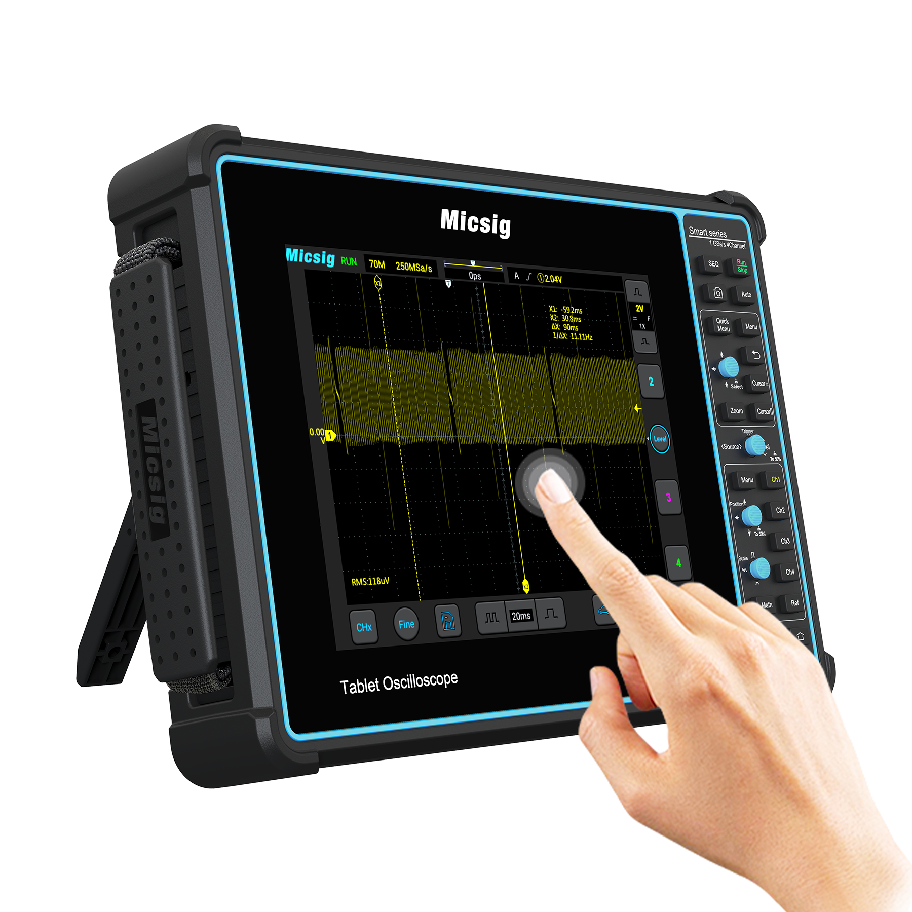
Micsig’s SATO1004 is a four-channel automotive oscilloscope with a comprehensive list of pre-set vehicle-related tests.
The instrument features 100MHz bandwidth, 1Gsample/s (in single channel mode), 32Mpoint memory and up to five hours of mobile use from its built-in battery, or continuous use from its 12V power adaptor.
“SATO1004 is a professional vehicle testing tool for evaluating CAN, LIN, Flex ray and K line networks, and sensors for: ABS, accelerator pedal, throttle position, fuel pressure, air flow meter, crankshaft, camshaft, knock, MAP; as well as testing 12 and 24V charging and start, charging ripple, cranking current sensors, actuators and ignition,” according to distributor Saelig, which is stocking the instrument.
The 8inch 800 x 600 touchscreen has touch, drag and swipe, and shares control of the scope with knob-and-button control. An HDMI output is available to reproduce the display on a larger screen or projector. “Live screen images can be transmitted to an external projector when the oscilloscope is connected to a LAN or WiFi network. The scope can display or be remotely controlled via Wi-Fi, LAN or USB, via a PC or an Android or iOS mobile device,” said Saelig.
As well as the serial busses above, bus trigger and decode features include: UART, SPI and I2C, then 1553B and ARINC 429 trigger and decode are options.
The Standard Kit version of the scope comes with 2x passive probes, 4x BNC-banana cables, 2x pair needle probes, 2x pair alligator clips, a power adaptor with mains cable and a screen protector.
The master Master Kit has the above, plus a secondary ignition pick-up, 2x multimeter-style probe tips and a hard-shell carrying case.
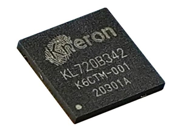
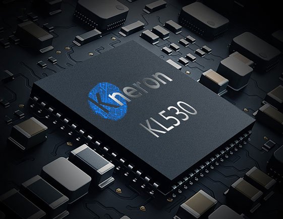
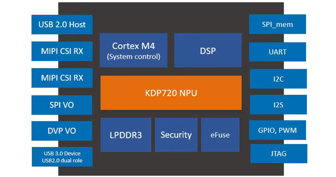
Kneron KL720 AI SoC (System on a Chip) offers an ideal balance of performance, power saving, and cost for hardware makers who are looking to benefit from on-device edge Artificial Intelligence (AI). Powered by Kneron’s Neural Processing Unit (NPU) that accelerates neural network models, the KL720 SoC makes possible endless AI applications for smart devices.
The NPU core is of the KL720 is designed to accelerate major computing layers inside the Convolutional Neural Network (CNN) and Recurrent Neural Network (RNN) to off-load heavy computing from the traditional CPU or GPU structure.
Features Highlights
Low-power design enabled by ARM Cortex M4 CPU
Power to process 4K images, Full HD videos, and 3D sensing for fool-proof facial recognition and to enable innovative gesture control for gaming, shopping kiosks, and more
Ideal for any high-end IP Cams, Smart TVs, AI glasses and headsets, and AIoT Gateways
Power to drive natural language processing (NLP) for translators and AI assistants
All the above and more can be processed at the same on the KL720
Features
NPU
696MHz maximum frequency
GOPS, 1024MAC/cycle peak throughput of 8-bit mode:
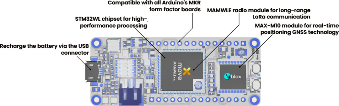
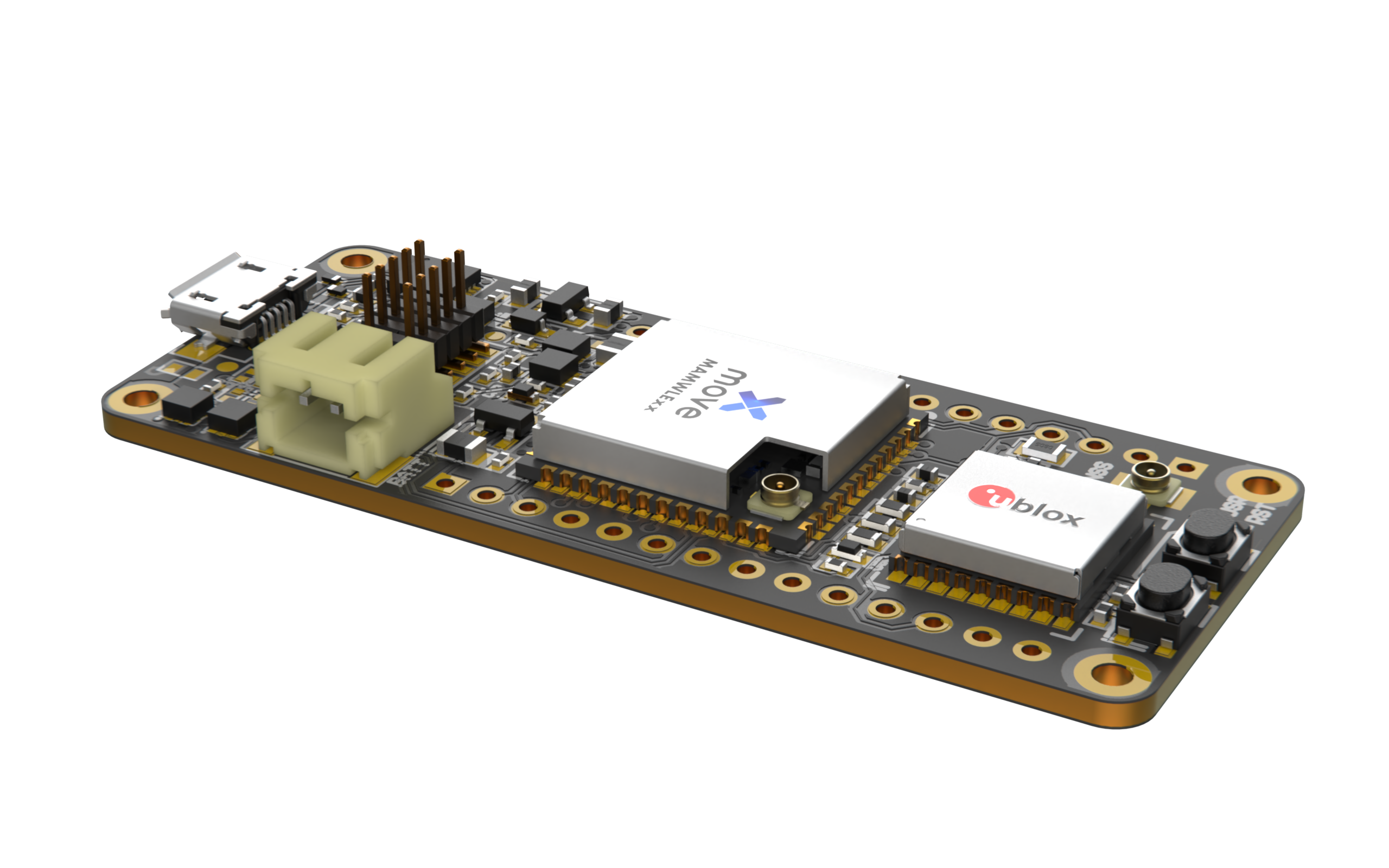
Move-X Cicerone LoRa®/GNSS Board is a high-performance, low-power, Arduino MKR-compatible development board based on the MAMWLE LoRa Module and the u-bloxMAX-M10S GNSS Module. The Cicerone Board delivers best-in-class GNSS, long-range wireless connection, and high-performance MCU processing in a low-power solution for optimal battery life.
The Cicerone Board allows users to build tracking applications worldwide with meter-level accuracy and to communicate long-range, low-power data via LoRaWAN®. The integrated Li-Po charging circuit enables the Cicerone Board to manage battery charging through the USB port.
The Move-X Cicerone LoRa/GNSS Board features a compact 63mm x 25mm form factor and is compatible with all Arduino MKR Shield Boards. These boards all share a common pinout to enable developers to easily add expansions with minimal software changes.
Features
63mm x 25mm PCB
2x push buttons: Reset, User)
2x LEDs: Battery charging status (Red), User (Green)
Headers compatible with Arduino MKR pinout
SWD signals for debugging
RESET, BOOT0
+3.3V output (LDO)
+5V input
+5V output (internally MUXed between USB and +5V input)
VREF output
GNSS module’s UART (allows firmware update)
MAMWLE SPI
I2C shared by LoRa and GNSS module
Up to 22 digital GPIO
Inputs for ADC
PWM outputs
Interfaces
USB micro for UART, RESET/BOOT0 driver, supply input, battery charge @200mA
Connector for single-cell 3.7V Li-Po battery (battery shall include protection circuitry against SC, OD, OC)
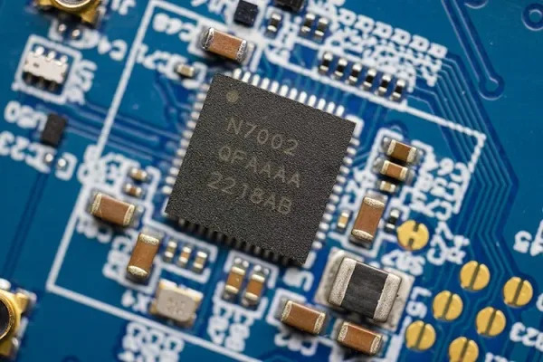
Nordic Semiconductor has announced its entry into the Wi-Fi wireless IoT market with the launch of the nRF7002, an ultra-low power, dual-band Wi-Fi 6 companion IC.
Nordic Semiconductor is now one of just a few companies offering all three of the world’s most popular wireless IoT technologies: Bluetooth, Wi-Fi, and cellular IoT.
The nRF7002 is described by Nordic as a ‘companion IC’ which means it is designed to provide seamless Wi-Fi connectivity and Wi-Fi-based locationing (SSID sniffing of local Wi-Fi hubs) when used alongside Nordic’s existing products. These include the nRF52 and nRF53 Series multiprotocol Systems-on-Chip (SoCs), and nRF91 Series cellular IoT Systems-in-Package (SiPs).
The nRF7002 can also be used in conjunction with non-Nordic host devices.
The launch of the nRF7002 follows Nordic’s 2020 acquisition of the development team, core Wi-Fi expertise, and Wi-Fi IP tech assets of Imagination Technologies Group.
W-Fi forms an integral part of the smart home Matter protocol championed by Apple, Amazon, Google, Samsung, and hundreds of other companies in consumer IoT. By adding Wi-Fi to its product range Nordic will now be able to support all three wireless protocols used in Matter. Namely: Bluetooth LE for commissioning, Thread for low power mesh networking, and Wi-Fi for high-speed wireless applications.
“We were able to bring our first Wi-Fi IC to market very quickly as a result of acquiring an extremely capable Wi-Fi team alongside a portfolio of Wi-Fi assets that team had already developed,” said Nordic CTO/EVP of R&D and Strategy, Svein-Egil Nielsen. “Nordic has also ensured that developing Nordic-based Wi-Fi 6 applications will be as simple as developing any other Nordic wireless IoT application, including using the same development tools and nRF Connect SDK.”
“The new Wi-Fi team’s relentless hard work to enable Nordic to launch its first Wi-Fi product so soon deserves huge recognition,” continued Mike Davis, Nordic’s Wi-Fi Systems & Software Director. “They knew Wi-Fi was the number one missing capability requested by Nordic customers. And they knew Nordic’s customers needed this capability quickly.”
The nRF7002 is supplied in a 6 x 6mm QFN package and is sampling now.
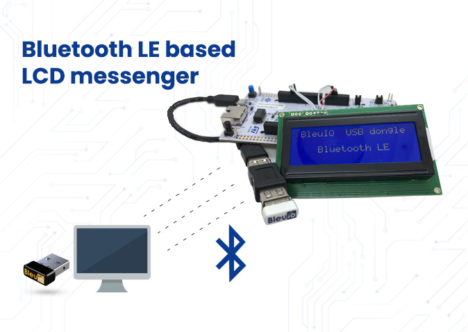
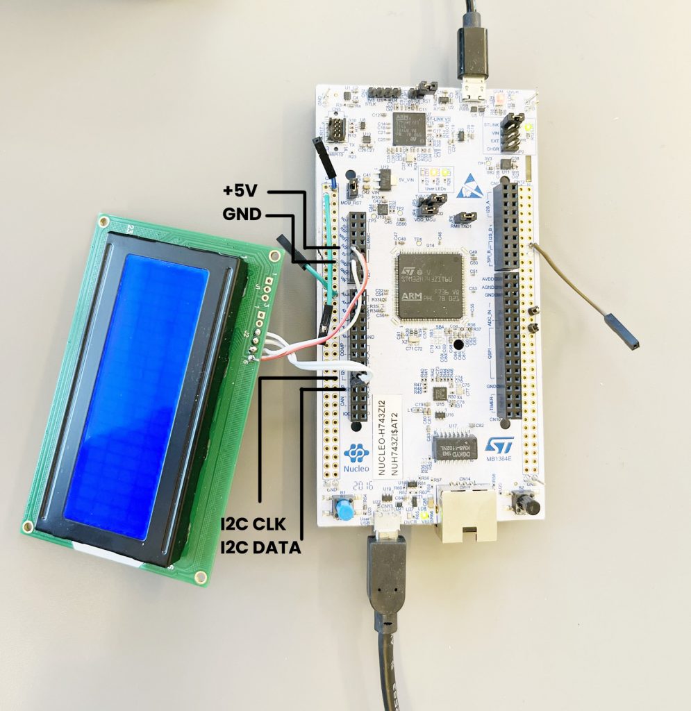
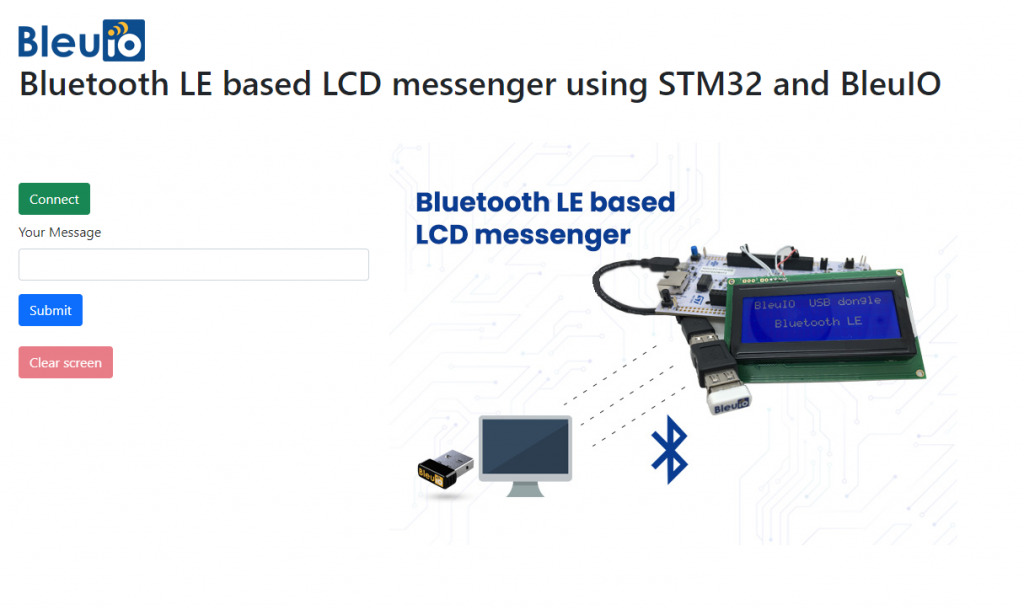
The aim of this project is to send messages via Bluetooth using a web browser or smartphone to an LCD display that is connected to the STM32 board.
1. Introduction
The project is based on STM32 Nucleo-144 which controls LCD display using BleuIO.
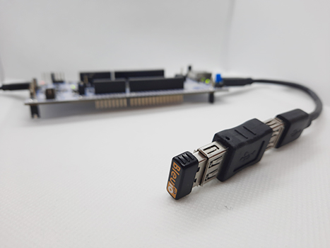
For this project, we will need two BleuIO USB dongles, one connected to the Nucleo board and the other to a computer, running the web script.
When the BleuIO Dongle is connected to the Nucleo board’s USB port the STM32 will recognize it and directly start advertising. This allows the Dongle on the computer port to connect with the web script.
With the web script on the computer, we can send messages to the LCD screen connected to STM32 using BleuIO.
We have used an STM32 Nucleo-144 development board with STM32H743ZI MCU (STM32H743ZI micro mbed-Enabled Development Nucleo-144 series ARM® Cortex®-M7 MCU 32-Bit Embedded Evaluation Board) for this example. This development board has a USB host where we connect the BleuIO dongle.
If you want to use another setup you will have to make sure it support USB Host and beware that the GPIO setup might be different and may need to be reconfigured in the .ioc file.
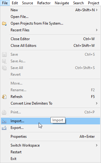
Either clone the project or download it as a zip file and unzip it, into your STM32CubeIDE workspace.
If you download the project as a zip file you will need to rename the project folder from ‘stm32_bleuio_lcd-master’ to ‘stm32_bleuio_lcd’
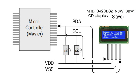
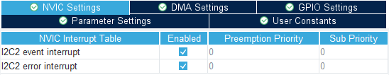
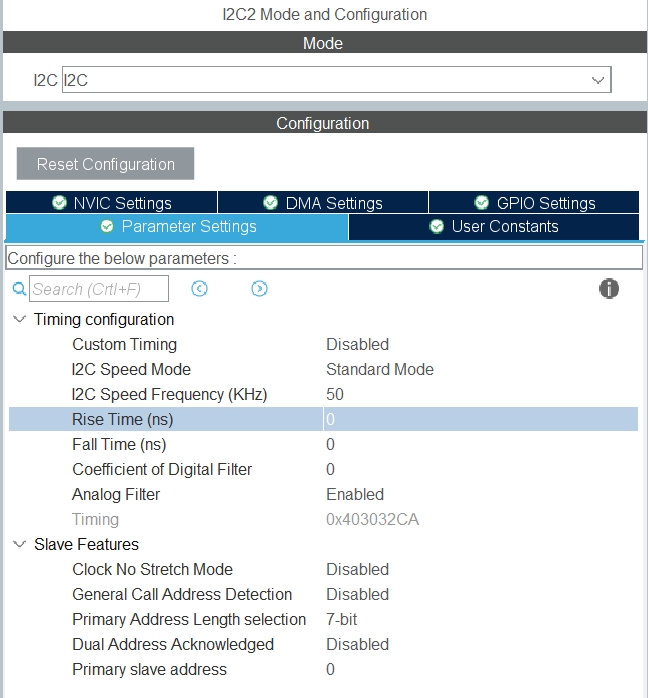
Connect the SDA to PF0 on the Nucleo board and SCL to PF1.
Then setup I2C2 in the STM32Cube ioc file as follows. (Make sure to change the I2C speed frequency to 50 KHz as per LCD display requirements.)
In the USBH_CDC_ReceiveCallback function in USB_HOST\usb_host.c we copy the CDC_RX_Buffer into an external variable called dongle_response that is accessible from the main.c file.
void USBH_CDC_ReceiveCallback(USBH_HandleTypeDef *phost)
{
    if(phost == &hUsbHostFS)
    {
        // Handles the data recived from the USB CDC host, here just printing it out to UART
        rx_size = USBH_CDC_GetLastReceivedDataSize(phost);
    HAL_UART_Transmit(&huart3, CDC_RX_Buffer, rx_size, HAL_MAX_DELAY);

    // Copy buffer to external dongle_response buffer
    strcpy((char *)dongle_response, (char *)CDC_RX_Buffer);

    // Reset buffer and restart the callback function to receive more data
    memset(CDC_RX_Buffer,0,RX_BUFF_SIZE);
    USBH_CDC_Receive(phost, CDC_RX_Buffer, RX_BUFF_SIZE);
    }

    return;
}
In main.c we create a simple interpreter so we can react to the data we are receiving from the dongle.
We put the interpreter function inside the main loop.
/* Infinite loop */
  /* USER CODE BEGIN WHILE */
  while (1)
  {
    /* USER CODE END WHILE */
    MX_USB_HOST_Process();

    /* USER CODE BEGIN 3 */
    // Simple handler for uart input
    handleUartInput(uartStatus);

    // Inteprets the dongle data
    dongle_interpreter(dongle_response);

  // Starts advertising as soon as the Dongle is ready.
  if(!isAdvertising && !isConnected && isBleuIOReady)
  {
    HAL_Delay(200);
    writeToDongle((uint8_t*)DONGLE_CMD_AT_ADVSTART);
    isAdvertising = true;
  }
  }
  /* USER CODE END 3 */
A board with an STM32 Microcontroller with a USB port. (A Nucleo-144 development board: NUCLEO-H743ZI2, was used developing this example. (https://www.st.com/en/evaluation-tools/nucleo-h743zi.html)
To connect the dongle to the Nucleo board a “USB A to Micro USB B”-cable with a USB A female-to-female adapter can be used.)
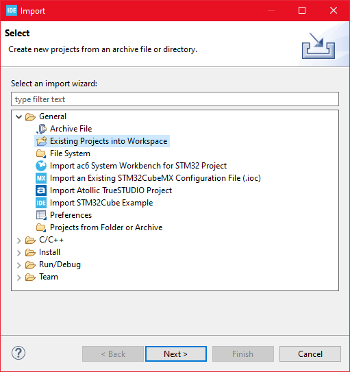
Then choose General>Existing Projects into Workspace then click ‘Next >’
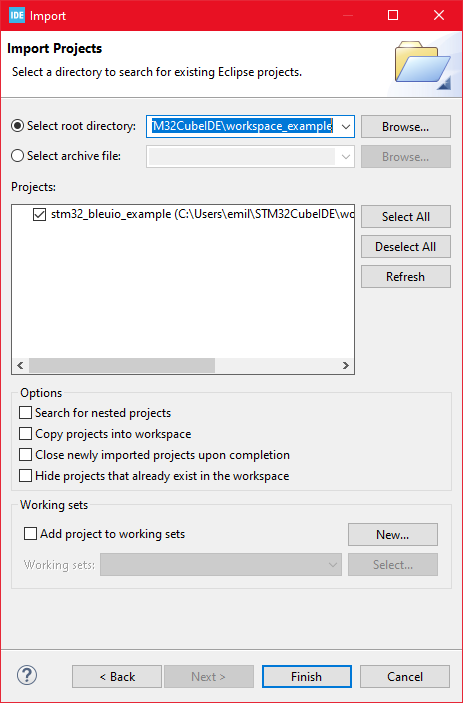
Make sure you’ve chosen your workspace in ‘Select root directory:’
You should see the project “stm32_bleuio_SHT85_example”, check it, and click ‘Finish’.
Running the example
Upload the code to STM32 and run the example. The USB dongle connected to STM32 will start advertising automatically.
Send Messages to the LCD screen from a web browser
Connect the BleuIO dongle to the computer. Run the web script to connect to the other BleuIO dongle on the STM32. Now you can send messages to the LCD screen.
Create a simple Html file called index.html which will serve as the frontend of the script. This Html file contains some buttons that help connect and read advertised data from the remote dongle, which is connected to stm32.
Create a js file called script.js and include it at the bottom of the Html file. This js file uses the BleuIO js library to write AT commands and communicate with the other dongle.
import * as my_dongle from 'bleuio'
const dongleToConnect='[0]40:48:FD:E5:2F:17'
document.getElementById('connect').addEventListener('click', function(){
  my_dongle.at_connect()
  document.getElementById("clearScreen").disabled=false;
  document.getElementById("connect").disabled=true;
  document.getElementById("sendMsgForm").hidden=false;
})

document.getElementById("sendMsgForm").addEventListener("submit", function(event){
    event.preventDefault()
    console.log('here')


    my_dongle.ati().then((data)=>{
        //make central if not
        if(JSON.stringify(data).includes("Peripheral")){
            console.log('peripheral')
            my_dongle.at_central().then((x)=>{
                console.log('central now')
            })
        }
    })
    .then(()=>{
        // connect to dongle
        my_dongle.at_getconn().then((y)=>{
            if(JSON.stringify(y).includes(dongleToConnect)){
                console.log('already connected')
            }else{
                my_dongle.at_gapconnect(dongleToConnect).then(()=>{
                    console.log('connected successfully')
                })
            }
        })
        .then(()=>{
            var theVal = "L=1 " + document.getElementById('msgToSend').value;
            console.log('Message Send 1 '+theVal)
            // send command to show data
            my_dongle.at_spssend(theVal).then(()=>{
                console.log('Message Send '+theVal)
            })
        })

    })
  });


document.getElementById('clearScreen').addEventListener('click', function(){
    my_dongle.ati().then((data)=>{
        //make central if not
        if(JSON.stringify(data).includes("Peripheral")){
            console.log('peripheral')
            my_dongle.at_central().then((x)=>{
                console.log('central now')
            })
        }
    })
    .then(()=>{
        // connect to dongle
        my_dongle.at_getconn().then((y)=>{
            if(JSON.stringify(y).includes(dongleToConnect)){
                console.log('already connected')
            }else{
                my_dongle.at_gapconnect(dongleToConnect).then(()=>{
                    console.log('connected successfully')
                })
            }
        })
        .then(()=>{
            // send command to clear the screen
            my_dongle.at_spssend('L=0').then(()=>{
                console.log('Screen Cleared')
            })
        })

    })
})
The script has a button to connect to the COM port on the computer. There is a text field where you can write your message. Your messages will be displayed on an LCD screen connected to the STM32 board.
To connect to the BleuIO dongle on the STM32, make sure the STM32 is powered up and a BleuIO dongle is connected to it.
Get the MAC address
Follow the steps to get the MAC address of the dongle that is connected to STM32:
Open this site https://bleuio.com/web_terminal.html and click connect to dongle.
Select the appropriate port to connect.
Once it says connected, type ATI. This will show dongle information and current status.
If the dongle is on the peripheral role, set it to central by typing AT+CENTRAL
Now do a gap scan by typing AT+GAPSCAN
Once you see your dongle on the list, stop the scan by pressing control+c
Copy the ID and paste it into the script (script.js) line #2
Run the web script
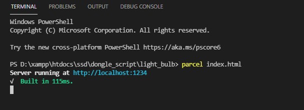
You will need a web bundler. You can use parcel.js
Once parcel js is installed, go to the root directory of the web script and type “parcel index.html”. This will start your development environment.
Open the script on a browser. For this example, we opened http://localhost:1234
You can easily connect to the dongle and send your message to the LCD screen. The response will show on the browser console screen.