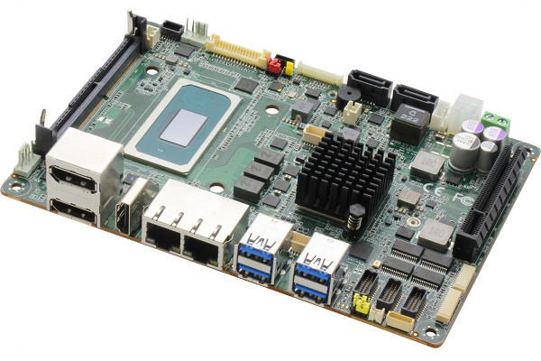
AAEON, a global leader in industrial computing, has introduced the world to the next generation of single board computers with the release of the EPIC-TGH7, which holds the distinction of being the first board of its kind to host Intel® 11th Generation Xeon®/Core™ processors.
With such an advanced processor package, the EPIC-TGH7 offers 8 cores and 16 threads to increase processing speed and power for intensive, high-end computing. However, this advancement has not sacrificed power-efficiency, with the EPIC-TGH7 providing up to 45W with Xeon®-level performance.
Hosting up to 8 USB ports, dual LAN ports, and a PCIe[x8] slot; the EPIC-TGH7 enables PCIe4.0 speeds of up to 16GT/s, despite retaining the same EPIC board form factor measuring just 4.53″ x 6.50″ (115mm x 165mm).
AAEON believes this combination of I/O density and high-speed expansion will be particularly applicable to healthcare imaging and military defense applications, with the board being able to accommodate the advanced graphics required for such uses.
In addition to healthcare imaging and military defense applications, the EPIC-TGH7 lends itself to use in digital signage, providing 4 simultaneous displays via an I/O featuring HDMI, VGA, Dual Channel 24/48bit LVDS, and DP ports. Such a myriad of options is designed to give users a diverse selection of display configurations to suit their project needs.
For more information regarding the EPIC-TGH7, please visit its product page, or contact an AAEON sales representative directly.
One of the definitions of ‘signal‘ in the Merriam-Webster dictionary is: “A detectable physical quantity or impulse (as a voltage, current, or magnetic field strength) by which messages or information can be transmitted from a source to a destination.”
A signal is simply a function, i.e., a mathematical relationship in which the values of a single dependent variable are determined by the values of independent variables. Generally, the independent variables could be time (e.g. in speech signals), space (e.g. in image data), and so on. Also, dependent variables could be like the voltage of a transistor’s collector, light intensity, etc. We are usually interested in using a physical variable not just at a single time, but rather at a set of times. In this case, the signal is a function of time, say f(t). For example, f(t) might denote voltage levels in some instants of time.
In electronics, a signal is an electrical quantity or effect, such as voltage, current, or electromagnetic fields that can be varied in such a way to convey information. The information can be recorded, conveyed, displayed, or manipulated. Electrical effects which do not convey usefully or wanted information are called noise. For this reason, one of the main criteria for the performance of a system is to measure its signal-to-noise power ratio (SNR).
There are many examples of signals including temperature, pressure, sound waves, such as speech and music, electromagnetic waves, such as radio signals, and biomedical signals, such as the electroencephalogram (EEG) and electrocardiogram (ECG).
Obviously, most of the signals are not originally in the electrical form; like temperature variations or mechanical displacement. A transducer is a device that converts a signal from one form of energy into another. For example, microphones and speakers alter pressure variations into electric voltages and vice versa. Transducers that produce electrical signals for applications in the areas of measurement and control are usually known as sensors. Examples of sensors are solar cells which convert light energy into electric voltage or thermistors which transform heat energy into electrical resistance.
In practice, the amplitude of most signals varies with time. In electronics and related fields, the waveform of a signal is the shape of its amplitude as a function of time, i.e., by plotting the amplitude on the vertical axis (y) and time on the horizontal axis (x). The waveform of an electrical signal can be visualized in an oscilloscope or any other device that can capture and plot its values at various times, with a suitable scale in the time and magnitude axes.
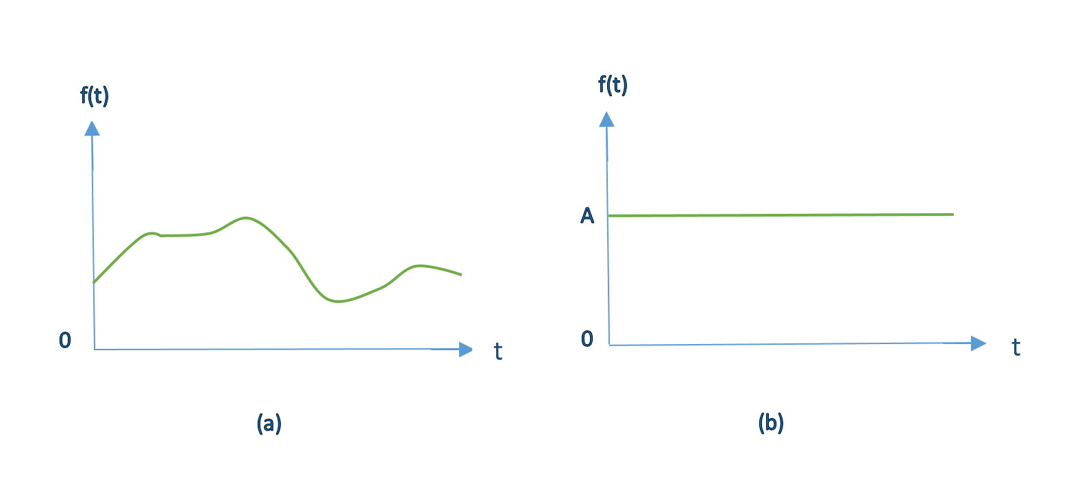
An electrical signal whose amplitude does not change with time over the duration of its measurement is called a direct current (DC) signal. Although most practical signals are time-varying. If the shape of the corresponding plot happens to be a sine wave, then the signal is called a sinusoidal signal. Sine waves can be considered to be the building blocks of many other signals. Figure1 shows examples of signal waveforms as functions of time.
Figure 1: Waveforms of 2 types of signals including (a) a general time-varying signal and (b) a constant or DC signal with amplitude A.
Signal Processing
Signal processing techniques focus on analyzing, modifying, and synthesizing signals such as sound, images, or scientific measurements. Examples of systems that manipulate signals by these techniques are speech recognition, video streaming, cellular networks, and medical scans such as MRI.
Signals are processed for a variety of reasons, such as to remove unwanted noise, correct distortions, to make them suitable for transmission, or extract certain meaningful information. Filtering is one of the most basic and important signal processing techniques; like designing signal filters based on using op-amps and discrete components of resistors, capacitors, and inductors.
Historically, signal processing was performed entirely in the analog domain. Since the late 20th century, signal processing has necessarily transitioned to the digital domain.
A signal is said to be periodic in time if its amplitude values are repeated after equal intervals of time. A period is defined as the amount of time (mostly expressed in seconds) required to complete one full cycle. This means a periodic signal repeats its pattern over sequential periods. Formally, a function f(x) is periodic with period ‘T’ (where T> 0) if:
Equation 1: Definition of a periodic function
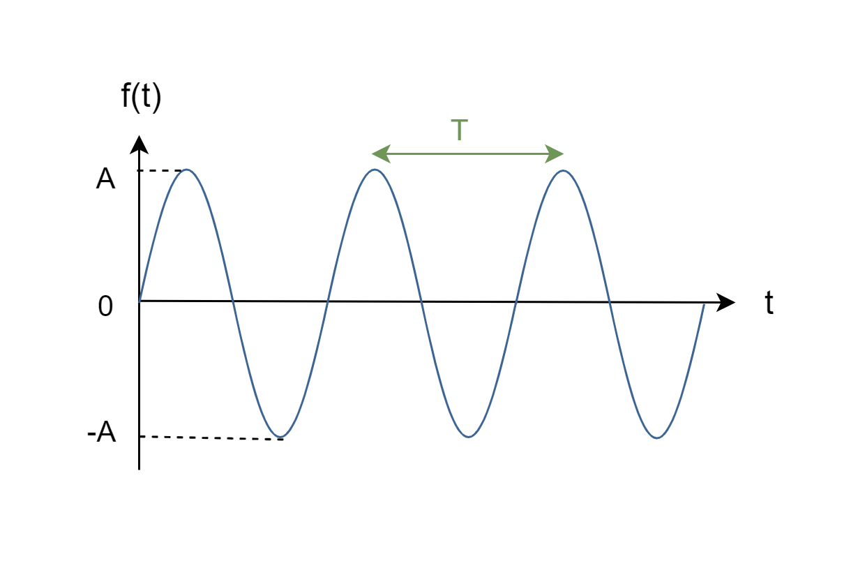
The most famous periodic signals are trigonometric functions, like sine and cosine waves. Figure2 shows a periodic sine wave, f(t), with period ‘T’ which is the time interval between 2 positive peaks.
Figure 2: A periodic sinusoidal waveform with period T
The frequency of a periodic function is the number of complete cycles that occur per second. Frequency can be defined in terms of the period, as follows:
Equation 2: Definition of frequency
Frequency has the units of hertz (Hz) or ‘cycle per second.
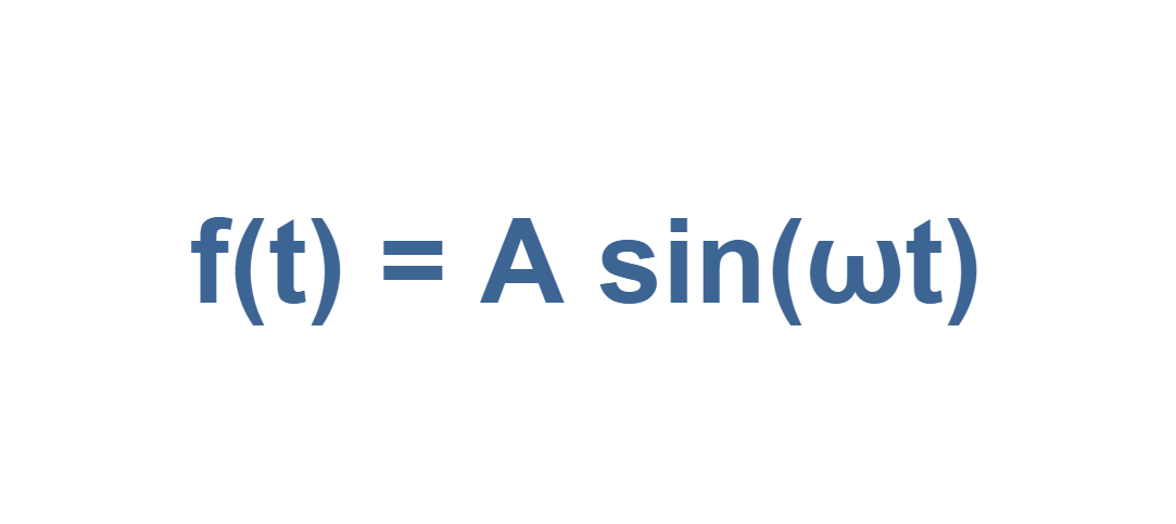
This sinusoidal waveform can be defined by the function in Equation 3:
Equation 3: Definition of a sinusoidal waveform
Here ‘A’ is the maximum amplitude or the peak value of the signal f(t).
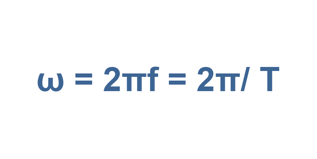
The angular (or rotational) frequency (ω) measures angular displacement per unit of time. Its units are degrees (or radians) per second. It is defined in Equation 4:
Equation 4: definition of angular frequency
Equation 4 implies that f(t) repeats itself for all time, with a repetition period T (= 2π/ ω).
Because, the alternating current (AC) is defined as an electric current whose direction is reversed periodically and its magnitude is changed continuously with time, periodic signals are mostly called AC signals. The usual waveform of AC signals in most electric circuits are sine waves, whose positive half-period corresponds with the positive direction of the current and the negative half-period corresponds with the negative direction of it.
Obviously, no real signal goes on forever, but Equation (3) could be a reasonable model for a sinusoidal waveform that lasts a long time compared to the period of T. Thus, AC steady-state circuit analysis depends upon the assumption of an eternal sinusoid.
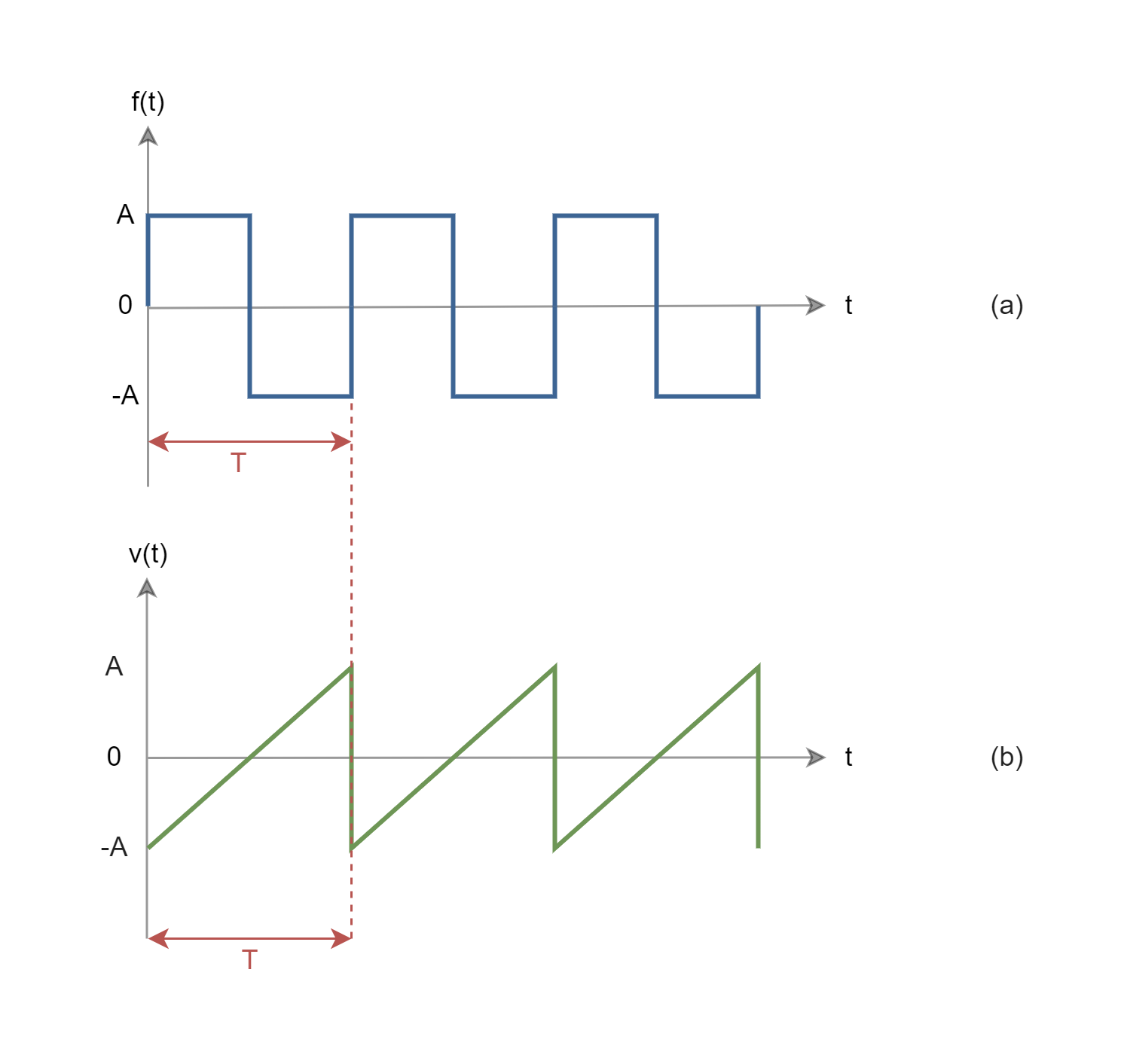
Figure 3 illustrates waveforms of some other famous periodic signals.
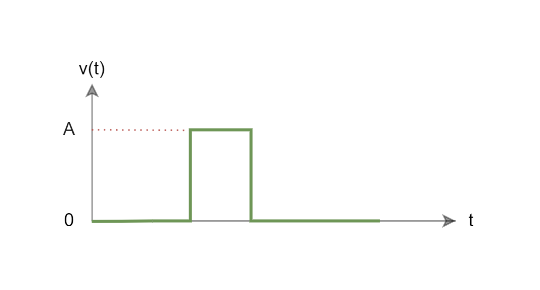
Any signal that is not periodic is called aperiodic or non-periodic. A non-periodic function does not remain self-similar for multiples of its period. Most of the real Signals that carry information, such as speech, music, or video, do not repeat endlessly. The waveform of Figure 1 (a) is an example of a non-periodic signal. Figure 4 also shows a single rectangular pulse shape wave used in radars as another example of a non-periodic waveform.
Figure 4: A single rectangular pulse shape waveform
Time Domain and Frequency Domain Representation
Since time flows continuously and irreversibly, it is natural to describe sequential signal values as given by a time arrangement. By measuring amplitude values of signals at different time instants, we can monitor how the signal has changed with the passage of time. A plot of these results is known as the time-domain representation of the signal. The above-mentioned waveforms in figures 1 to 4 were all examples of representation in the time domain.
For better analysis of signal characteristics, we might be interested in measuring the quantity as a function of frequency rather than time. There are certain applications that frequency-domain representation that is very useful. This representation is also known as the spectrum of the signal.
We can study the spectrum to determine which frequencies are present in the input signal and which are present or missing in the output, which means the frequency-domain signal analysis. Then, it is possible to add or subtract frequencies to the original signal, i.e., the frequency-domain signal processing method.
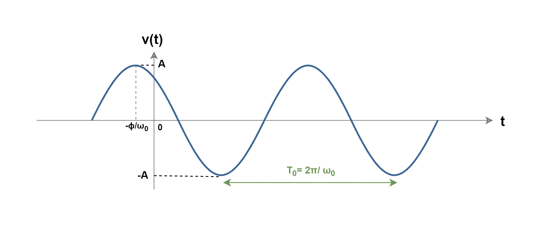
As a general description, consider an example of the familiar AC waveform as a cosine function of v(t) which is plotted in Figure 5.
Figure 5: A sinusoidal waveform with a phase shift from the origin
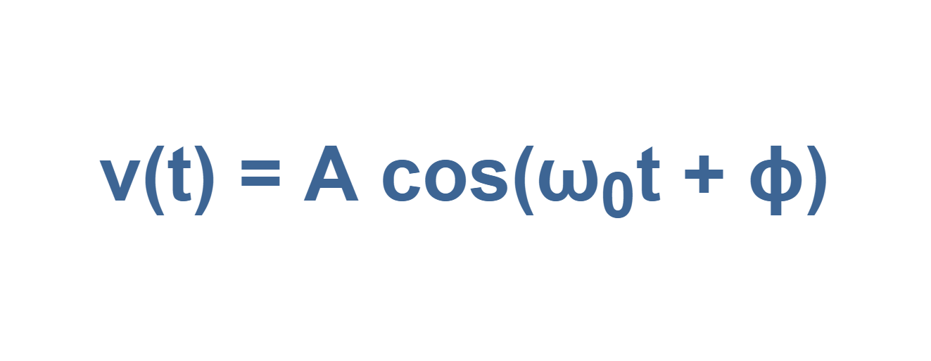
By convention, we can describe the cosine function by a general expression of Equation 5:
Equation 5: A cosine function
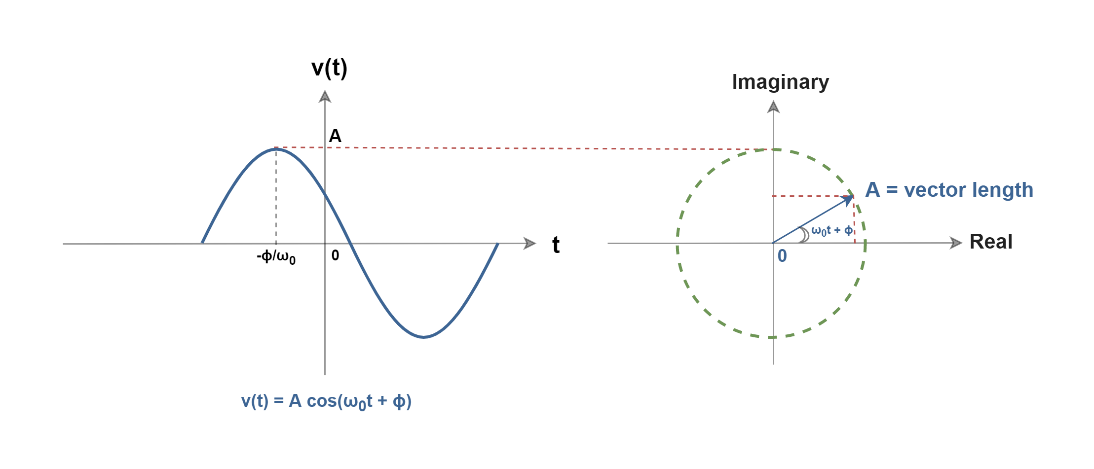
where ‘A’ is the peak of the signal and the phase angleϕ represents the fact that the peak of the waveform has been shifted away from the time origin and occurs at (t = -ϕ/ω0). In Equation 5 both the arguments (ω0t) and the phase angle (ϕ) can be in radians or degrees.
Sinusoids are easily expressed in terms of phasors. A phasor is a complex representation of the magnitude and phase of a sinusoid, regardless of time dependency. A phasor can also be defined as a vector on the surface of complex numbers with the real and the imaginary axes. We can imagine that in a complex plane, as time increases, the phasor rotates on a circle of radius ‘A’ at an angular velocity ω0 (= 2πf0) in the counterclockwise direction. Figure 6 depicts the concept of angular frequency and phasor.
Figure 6: Phasor diagram of a sinusoidal signal
The concept of ‘complex numbers’ is out of the scope of this article and we just needed it to achieve the main idea. You could refer to the attached link to get more information.
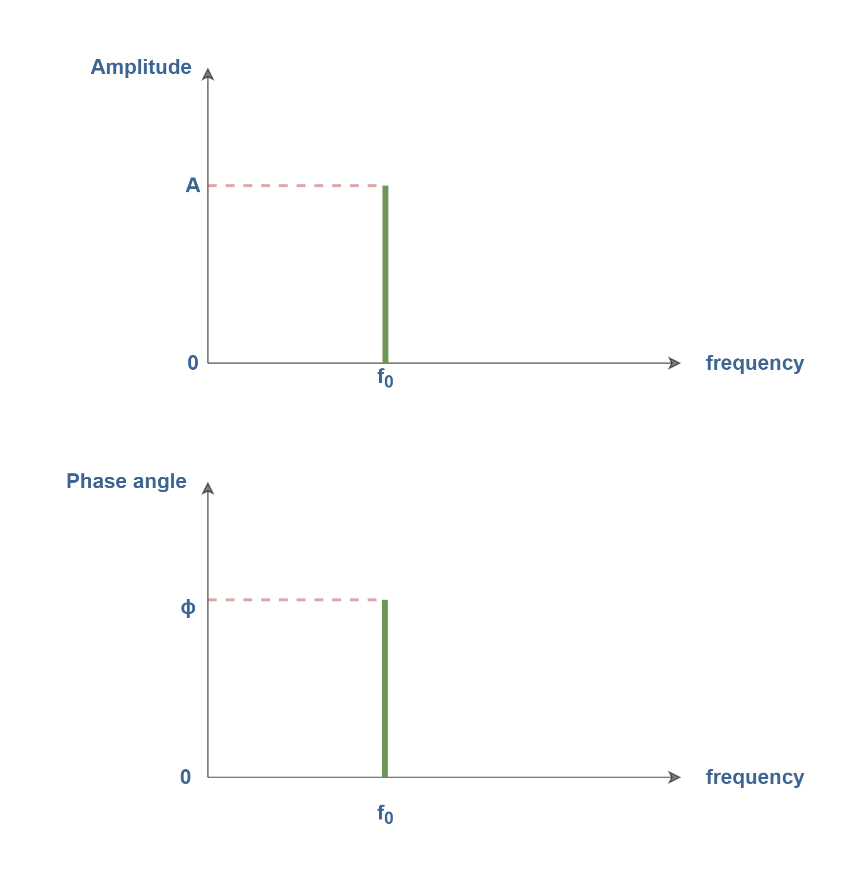
Only three parameters can completely specify a phasor: amplitude,phase angle, and angular frequency. To describe the same phasor in the frequency domain, we must associate the corresponding amplitude and phase with the particular frequency f0. By applying the phasor concept, a real function of v(t) in the time domain is converted to a complex number V(ω) in the frequency domain.
A suitable frequency-domain description would be the line spectrum shown in Figure 7, which consists of two plots: amplitude (of phasors) versus frequency and phase angle (of phasors) versus frequency.
Figure 7: line spectrum representation of the sinusoidal signal
In this line spectra illustration, we regard amplitude as always being a positive quantity. When negative signs appear, they must be absorbed in the phase angle using the next equation:
Equation 6: Conversion of amplitude polarity to phase angle
The amplitude spectrum essentially conveys more information than the phase spectrum and it displays the signal’s frequency content, i.e., the amplitude spectrum tells us what frequencies are present and in what proportion. Drawings like Figure 7, called one-sided or positive-frequency line spectra, can be constructed for any linear combination of sinusoids.
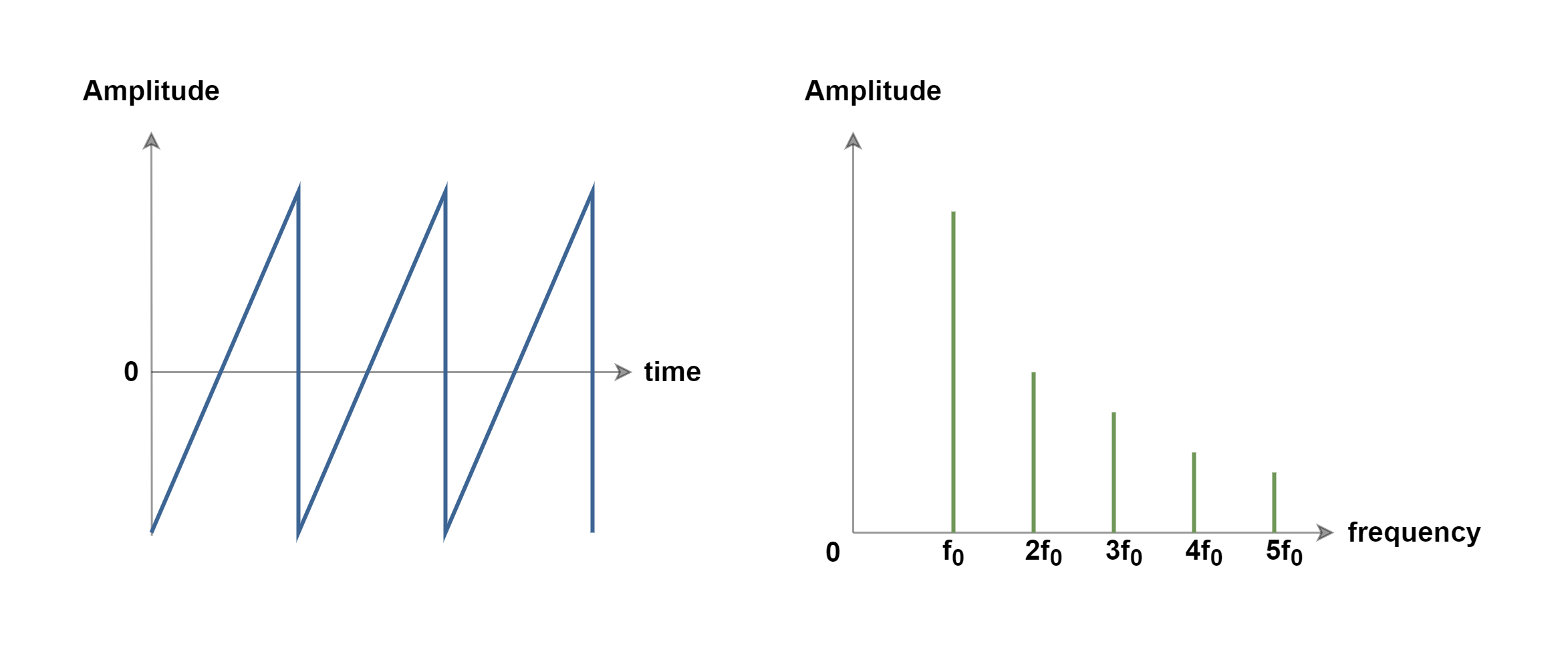
Figure 8 shows the illustration of a sawtooth wave shape signal in time and frequency domains. In both illustrations, the y-axis represents the amplitude of the signal. Each of them presents the same phenomenon from different viewpoints.
Figure 8: Time-domain versus frequency-domain representations of a sawtooth signal (not on a precise scale)
In Figure 8, the frequency-domain graph clearly shows that a sawtooth wave is a combination of many sine waves (with a line spectrum for each wave), which are all harmonics of the main sine wave with a fundamental frequency of f0. As the frequency of harmonics increases, the corresponding amplitude of line spectra decreases.
Representing the time-domain waveform in Figure 8 could be similar to displaying a signal on an electronic oscilloscope measurement device. On the other hand, looking from the frequency-domain viewpoint in Figure 8 is similar to monitoring the signal on a spectrum analyzer device which can show us information about the amplitude or power of frequency components.
Types of Signals: Continuous and Discrete
A continuous-time signal is a signal defined over a continuous range of time and its amplitude may have a continuous range of values (analog signal) or only a finite number of distinct values (quantized signal). The distinct values are called quantized values and they can be changed only by a set of distinct steps of magnitude.
Most of the signals naturally occurring in the world are analog and they provide a continuous stream of information on the physical quantity they represent. The main characteristics of analog signals are amplitude, frequency, and phase. The best example of an analog signal is a human’s voice.
A discrete-time signal is a signal defined only at discrete instants of time i.e. the independent variable of time (t) has been quantized. In a discrete-time signal, if the amplitude has a continuous range of values, the signal is called a sampled signal. In this case, if the amplitude contains a set of discrete values, the signal is usually called a digital signal.
In past decades, analog computers employed physical quantities that were approximations of continuous representations of signals. While discrete representations of both time and amplitude are necessary for digital computers in present decades.
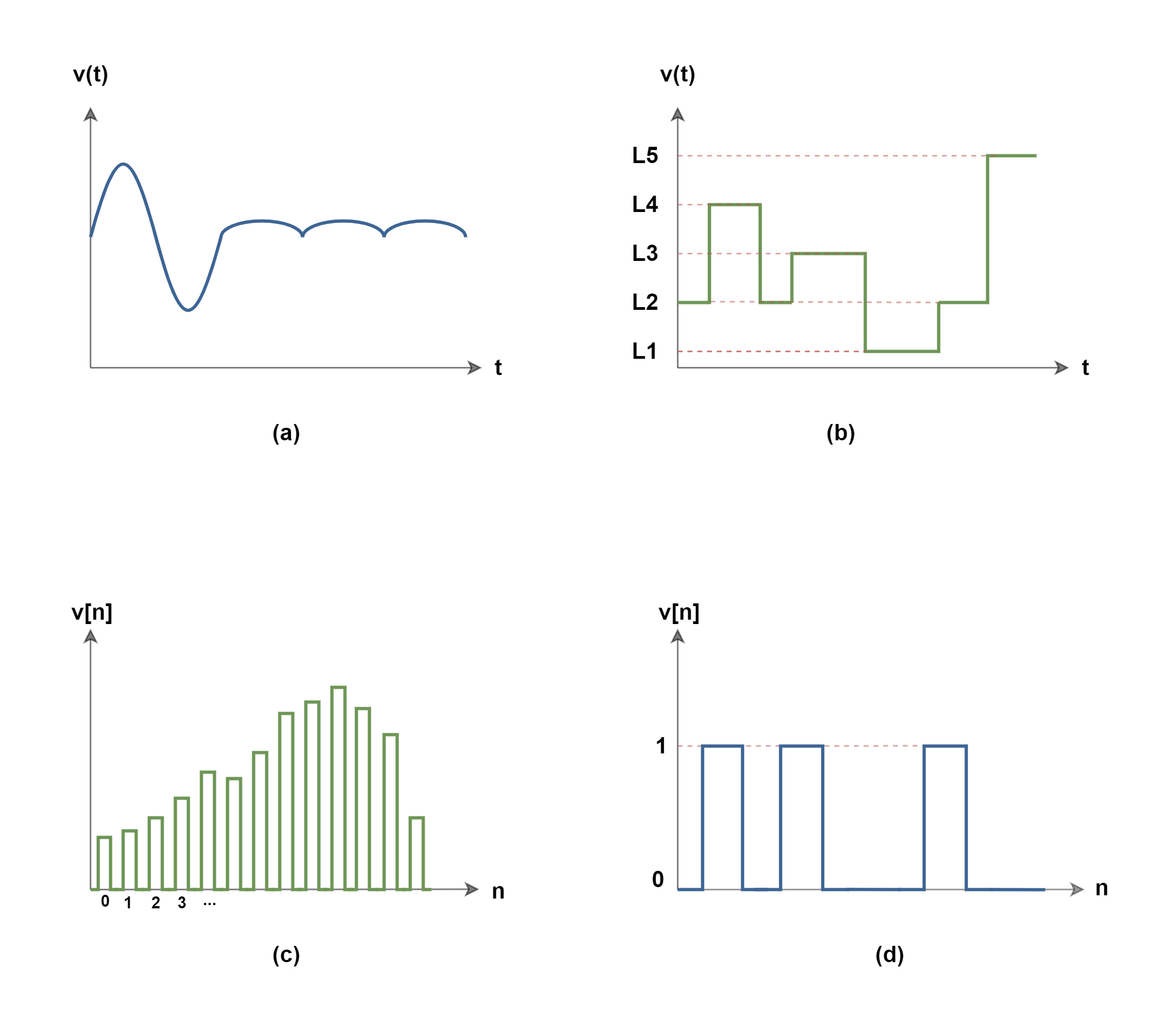
If we consider both important variables of time and amplitude, which are essential to represent any type of signal, the categories can be expanded to 4 items:
(a) continuous-time with continuous amplitude (analog signal)
(b) continuous-time with discrete amplitude (quantized signal)
(c) discrete-time with continuous amplitude (sampled signal)
(d) discrete-time with discrete amplitude (discrete/digital signal)
Figure 9 shows an example for each of the categories. It is worth mentioning that in the case of discretization of signal in time, the variable of time (t) is usually replaced by the number of time intervals between amplitude samples and it is denoted by ‘n’.
Figure 9: 4 categories of signals from (a) to (d)
Summary
The term analog signal processing describes a body of techniques that can be implemented to process analog (or real-world) signals.
This includes the theory and application of filtering, coding, transmitting, estimating, detecting, analyzing, and reproducing analog signals.
The frequency f is in units of Hertz (abbreviated Hz) which is sec-1, or often called cycles per second.
ω is also the frequency in terms of radians/sec units and is known as radial or circular frequency. f and ω are related by ω = 2πf.
This is very useful in many applications to find the behavior of the signal in terms of time units. When we can monitor how the signal has changed with the passage of time, we call this the time-domain description of a signal.
A frequency-domain description uses some set of sinusoidal signals as a basis for describing a signal.
The observer can look at the amplitude variations of the signal from the time-domain or frequency-domain point of view.
The term periodic signal is usually applied to periodically varying voltages, currents, or electromagnetic fields.
The opposite of a periodic signal is an aperiodic signal. An aperiodic function never repeats.
Frequency-domain signal descriptions decompose the source signals into sinusoidal components. The frequency of the sinusoid that most closely matches the signal is the principal frequency component of the signal.
Non-periodic signals can also be represented in the frequency domain.
Signals can be categorized in continuous or discrete types, in amplitude or time.
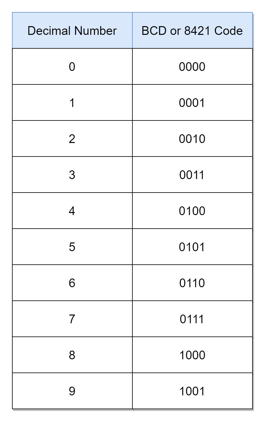
The Binary Coded Decimal is a 4-bit binary number coded to represent specifically a decimal number. The “coded” refers to the process of assigning a specific or unique binary code to a particular decimal number. In the Binary Coded Decimal or shortly BCD, the decimal numbers from “0” to “9” are binary coded. The binary code representing each decimal number is called a Binary Coded Decimal. The Binary Coded Decimals are used in digital systems for displaying decimal values, mainly.
The decimal numbers use a base-10 numbering system and, as such, there are a total of ten (10) decimal numbers from “0” to “9”. Likewise, binary numbers use a base-2 numbering system. In order to code “0” to “9” decimal numbers in binary, ten (10) unique combinations of binary numbers are required, each representing a single decimal number. The number of combinations that can be produced by binary digits or bits (n) is given by 2n. The representation of ten (10) decimal numbers requires a binary code having at least four (4) binary digits or bits. The Binary Coded Decimal uses the minimalist bits’ option of four (4) to represent decimal numbers.
The famous Hexadecimal numbering system also uses the four (4) bits to represent equivalent binary numbers. The hexadecimal number uses a base-16 numbering system and there is a total of sixteen (16) hexadecimal numbers. The Binary Coded Decimals are similar to Hexadecimal numbers. However, Binary Coded Decimal (BCD) encoding uses only “0” to “9” numbers, and the rest of the numbers i.e. from “A” to “F” or from “10” to “15” are not required. The hexadecimal numbers from “0” to “9” are similar to the binary coded decimals, “0” to “9”, respectively.
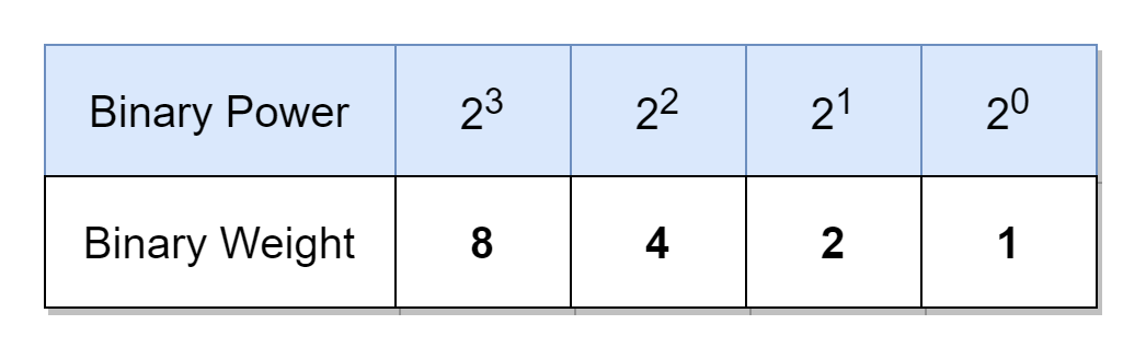
The usage of Binary Coded Decimals to represent decimal numbers has many advantages in digital systems and, amongst these, the main advantage is the ease of conversion from and to decimals. However, there is a wastage of six (6) numbers from “A” to “F” as discussed above. In Binary Coded Decimal, each decimal digit is represented by a four (4) bit binary number (BCD), and each decimal digit can be represented by a weighted sum of binary values. It is known from previous articles, that the weight of a decimal digit, from right to left, increases by 10 times, whereas, of a binary digit (bit) by 2 times. In four-bit BCD, the first, second, third, and fourth digit has a weight of 20 = 1, 21 = 2, 22 = 4, and 23 = 8, respectively. In the following table, the binary power or weight of each BCD bit is shown.
Using the above table, the weighted sum of bits of “0000” to “1001” binary numbers equalizes to “0” to “9” decimal numbers, respectively. Starting from the right, the four bits of BCD give a weight of 8, 4, 2, and 1, respectively. The weights (8, 4, 2, and 1) of a BCD sum up to constitute a decimal number. Due to this reason, a BCD is also called an 8421 code as it represents a relevant decimal number in a 4-bit format.
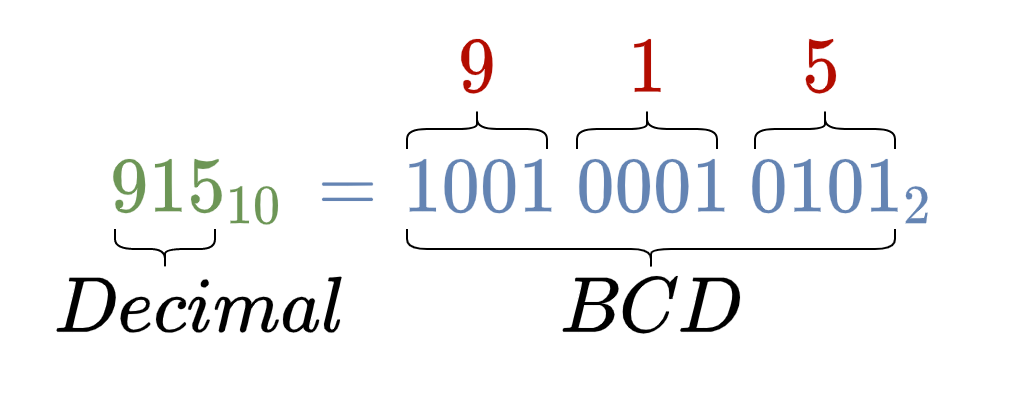
The conversion of a decimal number, consisting of multiple decimal digits, requires obtaining an equivalent BCD for each decimal digit. For example, consider a decimal number of 91510, having three decimal digits i.e. “9”, “1”, and “5”. These decimal digits “9”, “1”, and “5” have equivalent binary coded decimals “1001”, “0001”, and “0101”, respectively. The combination of these binary coded decimals is the equivalent of 91510 in BCD as given below.
The following table lists each decimal number against their respective binary coded decimal (BCD). The BCD or 8421 code is unique for “0” to “9” digits and for numbers greater than “9” such as “10”, “11”, and “12” etc. each decimal digit is given the respective unique 8421 code, separately. For example, the “10” would make up an 8421 code of “0001 0000” where “0001” and “0000” are unique 8421 codes of “1” and “0”, respectively.
Decimal to BCD Conversion
There are multiple methods to obtain the BCD or 8421 code of a decimal number. Each method requires the processing of each decimal digit, separately, not the whole decimal number. First, and the easiest, way is to memorize these ten (10) BCD codes or lookup the BCD truth table for each decimal digit and find the respective BCD/ 8421 code. The second method would require the application of decimal to binary conversion on each (single) decimal digit i.e. repeated-division-by-2. The third method is to split each decimal digit into weights of bits summing up to desired decimal digit. The weighted binary digits form the equivalent BCD/ 8421 code. A few examples of decimal to equivalent BCD conversions are given below.
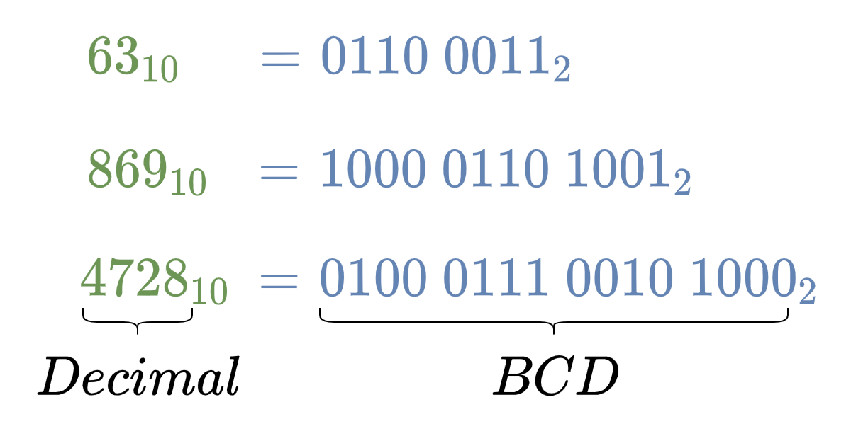
Decimal to BCD Conversion Examples
The decimal numbers: 6310, 86910, and 472810 are converted into their equivalent BCD numbers by use of the above-given BCD truth table.
BCD to Decimal Conversion
As each decimal digit is represented by a 4-bit BCD and, therefore, it is necessary to split the given binary number into groups of 4-bits. The 4-bit groups are formed from the least significant side (rightmost) to the most significant side (leftmost). Eventually, leading to the formation of the last 4-bit group which may require additional significant zero(s) to complete the 4-bit group. Each 4-bit group represents the respective BCD or 8421 code of that decimal digit. Using the above BCD truth table, equivalent decimal digits against respective BCD/ 8421 codes are obtained. The combination of decimal digits ultimately gives the representation of the desired decimal number. In the following examples, the BCD to decimal conversion is carried out to explain the conversion process.
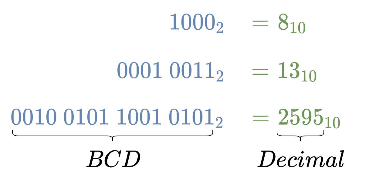
BCD to Decimal Conversion Examples
The binary numbers: 10002, 100112, and 100101100101012 are converted into their equivalent decimal numbers by splitting into 4-bit groups of 8421 (BCD) codes and then finding equivalent decimal numbers against respective 8421 (BCD) codes using the above given BCD truth table.
The Binary Coded Decimal is a mere representation of a single decimal digit and a decimal number represented by BCD encoding is not the actual binary equivalent of that decimal number. For example, the BCD equivalent of 6310 is 011000112, whereas, the pure binary equivalent of 6310 is 001111112. The BCD representation of decimals is useful for displaying decimal values etc. but is not an efficient way of storing data and for performing arithmetic operations. The storage using BCD encoding would require an additional bit(s) compared to its equivalent true binary number. It is because of discarding six (6) binary numbers out of sixteen (16) as described above. For example, the representation of a three-digit decimal number requires 12-bits in BCD and, contrary to this, a 10-bit binary number can accommodate a decimal number up to “1024”. Moreover, BCD encoded binary numbers are not suitable for arithmetic operations. Consider a simple example of the addition of two BCD binary numbers which generates a carry bit, the addition of this carry bit to a BCD number of “1001” or “9” would lead to an invalid BCD code of “1010”. The solution requires conversion from binary to decimal i.e. 1010 and then reverting to BCD equivalent i.e. “0001 0000”. However, it is more suitable and convenient to convert BCD encoded numbers to pure binary numbers before performing any arithmetic operations.
Binary Coded Decimal Decoder IC
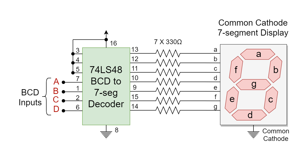
The usage of Binary Coded Decimal is useful in applications requiring the display of information in decimals. The digital or electronic systems display this information on LCD or 7-segment LED displays. In order to display decimal numbers, the binary numbers are converted to equivalent BCD numbers and a BCD decoder IC is used to display the decimal numbers on these displays. The widely used 7-segment display uses a BCD to 7-segment decoder IC to display BCD numbers. The 7-segment displays come in two variants depending on the configuration of LEDs with the supply voltage i.e. common anode, and common cathode. The common anode variant of the 7-segment requires a logic “LOW” at one of its segment’s inputs to turn it “ON”. Whereas, the common cathode 7-segment requires a logic “HIGH” to lit a segment. The commercially available BCD to 7-segment decoder ICs are 74LS47 and 74LS48. The 74LS47 produces an active-low output and, as such, is suitable for a common anode 7-segment display. On the other hand, a common cathode 7-segment display requires an active-high output BCD to 7-segment decoder IC i.e. 74LS48. In the following figure, a 74LS48 (active-high output) decoder IC with the common cathode 7-segment display is shown.
Figure 1: The common cathode 7-segment display with 74LS48 IC
Conclusion
The Binary Coded Decimal (BCD) is a 4-bit binary code meant to represent a decimal number. The Binary Coded Decimal has ten (10) unique binary codes each to represent a decimal number from “0” to “9”.
The Binary Coded Decimal is also known as 8421 code where 8, 4, 2, and 1 represent the weight of the 4th, 3rd, 2nd, and 1st bit, respectively.
The Binary Coded Decimal is similar to the Hexadecimal numbers but uses only “0” to “9” numbers and the rest of the numbers from “A” to “F” are wasted. Due to this, the storage of information in BCD format is not efficient and requires an additional bit(s) compared to pure binary equivalent.
The conversion from decimal to BCD requires obtaining equivalent BCD/ 8421 code from the truth table. Whereas, conversion from BCD to decimal is the exact opposite of the decimal to BCD conversion process. However, this requires splitting the binary (BCD) number into 4-bit groups and may require additional significant zero(s) in the last (leftmost) group.
It is appropriate to convert BCD numbers to pure binary numbers before performing any arithmetic operation.
The BCD encoding is useful for displaying information in the form of decimal numbers and, as such, is widely used in 7-segment displays. The BCD to 7-segment decoder i.e. 74LS47, 74LS48, etc. is used to display decimal numbers on 7-segment displays.
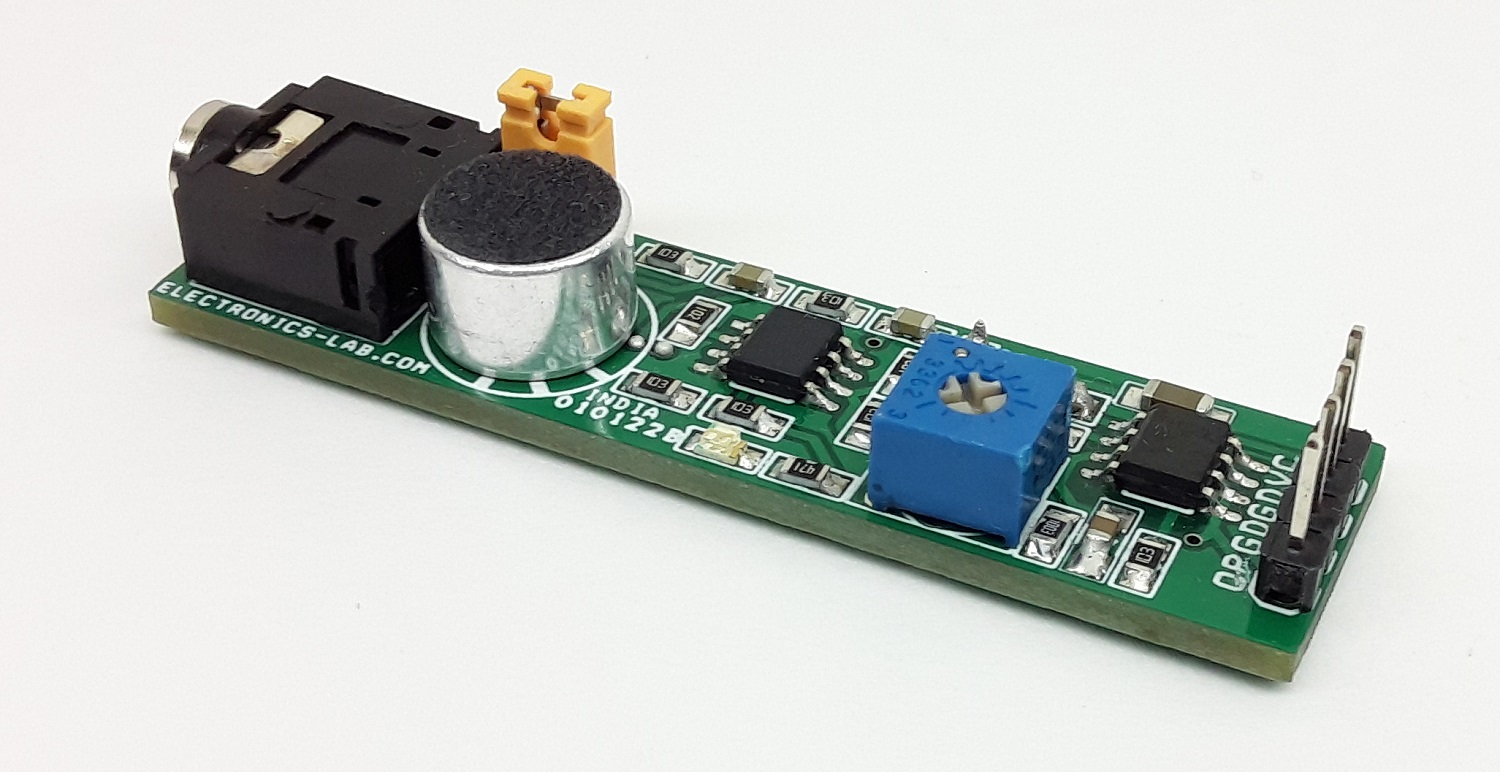
The project presented here is a sensitive sound sensor. The circuit converts sound frequency and outputs DC voltage. The board consists of LM358 OPAMP and LM2907 IC. LM358 is used as a dual-stage microphone preamplifier and LM2907 acts as a frequency to voltage converter. The circuit provides analog voltage output when it detects sound. The output of the sensor is proportional to the audio sound frequency detected through the condenser microphone. The output voltage swings from 3.5V to 10.8V proportional to frequency 330Hz to 933Hz. Output is zero when the sound frequency is below 330Hz. Users may try with other frequency ranges, which can be changed using the following formula, Vo = R9 × C6 × VCC × f. The sensor has better response and accuracy than many sound sensors available on the market. The operating Supply is 12V DC and consumes 20mA current. Jumper J1 and J2 are closed for normal microphone operation.
Accurate Acoustic Sensor – Sound Frequency to Voltage Converter – [Link]
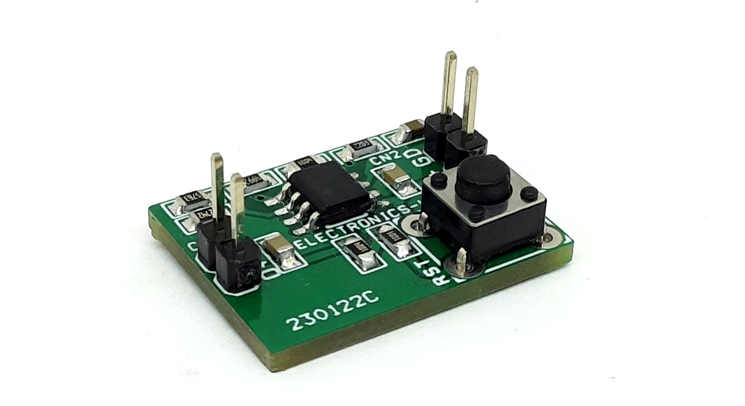
A rechargeable battery’s load should be disconnected at the point of complete discharge, to avoid a further (deep) discharge that can shorten its life or destroy it. Because a battery’s terminal voltage recovers when you disconnect the load, you can’t simply disconnect the load when the terminal voltage dips below the established threshold and then re-connect it when the voltage returns above that threshold. Such action may produce chatter in the disconnect switch. The project shown here is a complete solution to this problem.
Deep Discharge Protector for 3.6V Li-Ion Battery – [Link]
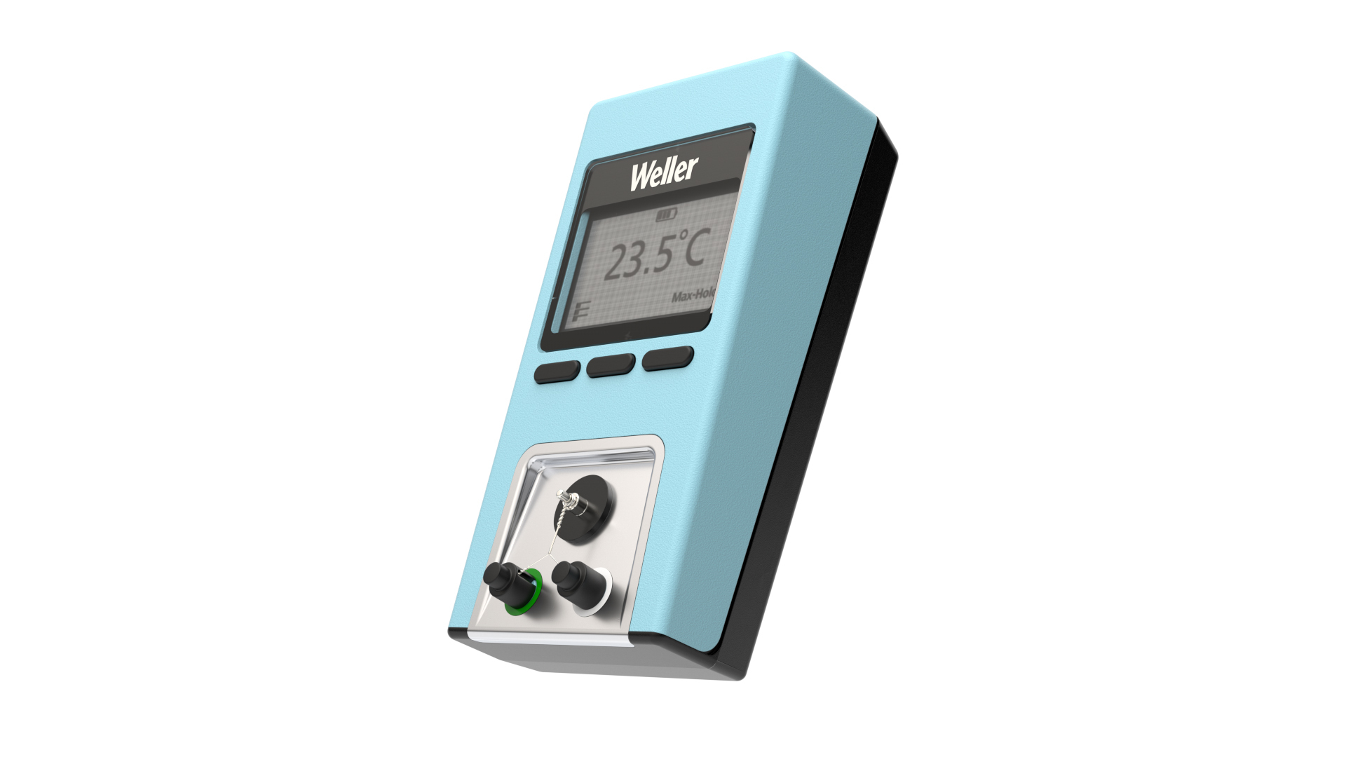
Weller’s WCU (T0053450199) is a compact, stand-alone, and high-precision temperature measurement device for quick and accurate temperature measurement.
The WCU unit is designed for users that need to make measurements fast and easily while maintaining the highest level of accuracy. It comes with a large, non-backlight display.
Max Hold function: The WCU display will show/hold the maximum temperature measured.
High-Mobility: The compact designed, battery-powered Weller High Precision Temperature Measurement Device can easily be shared between different workstations
Temperature Measurement Count Function: Number of tip temperature measurement will be automatically counted. This function can be useful for control of changing sensor.
ESD Safe: The Weller WCU High Precision Temperature Measurement Device is ESD safe
WCU Replacement Sensor: 10 pcs. T0058771712
High-Precision Temperature Measurement Device: Quick and accurate temperature measurements.
Simultaneous Use of Thermocross and Thermocouple: Keep track of soldering tip and soldering bath temperatures simultaneously. (Weller Thermocouple Type K Ø 0, 1 mm T0058755782) (Weller Thermocouple Type K Ø 0, 5 mm T0053119099)
Fast and Easy Measurement: Effortlessly auto-calibrate in less than 10 seconds, ensuring the operator can focus on the important soldering task with a precise temperature for best productivity. The Auto-Calibration function can be used with: WX 1, WX 2, WXD 2, WXA 2, WXR 3, WXsmart NOTE: For the Auto-Calibration function a RS 232 cable ( order number: T0058764710) needs to be purchased separately
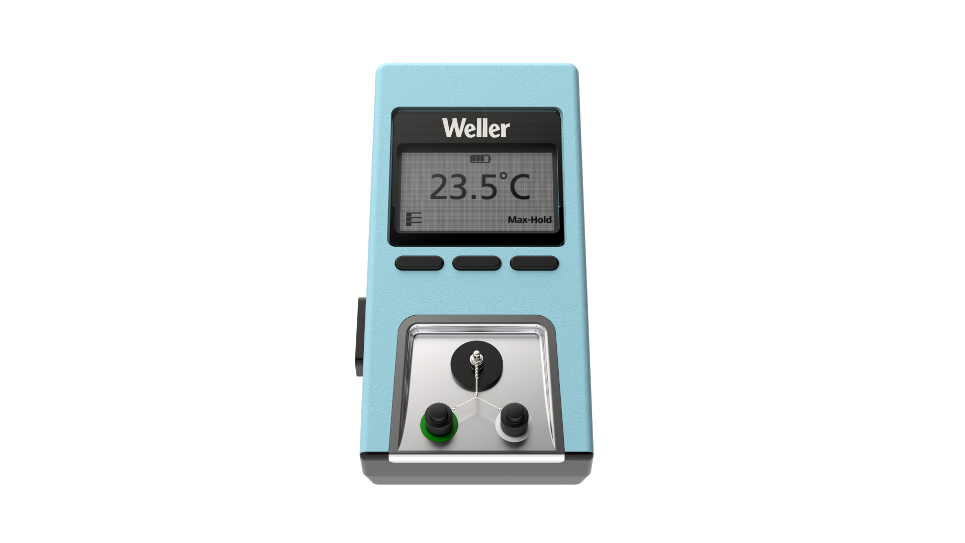
Intuitive Navigation: Digital display for fast temperature unit change between °C and °F, and other functionalities. Values are easily readable from the large non-backlite display.
Low Energy Consumption: Auto Turn-off Timer saves battery life shutting down the unit’s power after 10 mins without use
This new device has a double purpose as the temperature can be measured by the built-in thermo cross, or with a standard external type K sensor. Its main function uses the three filaments (one of which is mechanical only) that form the probe: the soldering tip has to touch at their intersection and the real temperature can be measured and shown in the middle of the screen of the WCU. The two contacts that carry out the reading are protected with heat-resistant and antistatic caps to avoid false readings caused by the proximity of the soldering iron’s resistance to the probes. There is a metal plate under them to simplify cleaning, and the probes are easily replaceable (5 in the scope of supply and also available in packs of 10 pcs, T0058771712). As an alternative to the thermo cross, a type K thermocouple can be connected simultaneously to carry out temperature measurements of any type: from a solder bath or a process.It can even verify “system accuracy” regardless of the specific tip used, but based on a sample tip, and this would use the 0.5 mm probe together with the appropriate Weller measurement tip (sold separately, T0053119099).
The temperate read by the external sensor is shown in the top left corner of the display.
Weller WCU can be connected to Weller units from the WX family but can also be used with older or other units, even with other brands, as well as used as an external temperature sensor (not necessarily for tips or nozzles). By connecting it to the Weller WX units (using a special cable sold separately, T0058764710), once the temperature verification process has been completed (about 10 “), any offset will be automatically set in the built-in memory of the WX connected tool.
The WCU is supplied with its calibration certificate and our service center is available for periodic certification.
Diodes Corporation recently announced a new addition to its family of automotive-qualified DC-DC converters. The DIODES™AP64060Q is a 600mA synchronous buck converter device with an input voltage range that covers 4.5V to 40V. It incorporates a 600mΩ high-side power MOSFET plus a 300mΩ low-side power MOSFET so that high-efficiency step-down conversion (reaching 90%) can be delivered, and with minimal PCB board space. The AP64060Q is targeted for use in automotive powertrains, infotainment systems, and instrumentation clusters, as well as vehicles’ exterior lighting.
The AP64060Q has a very low quiescent current (IQ), typically only 90μA, which translates into enhanced light load efficiency. Thanks to the fast switching frequencies this device supports (2MHz), smaller accompanying inductors and capacitors can be selected. Its synchronous rectification eliminates the need for an external Schottky diode, while the use of a peak current mode control and built-in loop compensation network further reduces the overall component count.
The proprietary gate driver scheme employed in the AP64060Q alleviates switching node ringing without impacting on MOSFET turn-on and turn-off times. This mitigates high frequency radiated electromagnetic interference (EMI) noise caused by MOSFET switching.
The AP64060Q has an operating ambient temperature range of -40°C to +125°C. Protection features include overvoltage protection (OVP), undervoltage lockout (UVLO), and thermal shutdown. This device is supplied in a compact TSOT26 package.
The AP64060Q is available at $0.23 in 1000-piece quantities. It is AEC-Q100 Grade 1 qualified, supports PPAP documentation, and is manufactured in IATF 16949 certified facilities. For more information, please visit https://www.diodes.com/part/AP64060Q/
This month oemsecrets.com are giving away 2 x learning Arduino starter kits including the ELEGOO UNO R3 Starter Kit and the ELEGOO 37 in 1 Sensor Modules Kit. Simply follow the link below to enter.
Read on for more information about the learning starter kits.
About the Kits
The UNO boards can be used as the brains behind almost any electronics project. UNO can interact with buttons, LEDs, motors, speakers, GPS units, cameras, the internet, and even your smart-phone or your TV! By connecting the UNO board with a personal computer via a USB cable and uploading programs to the board, users can create digital devices and interactive objects that can sense and control objects in the physical and digital world like robots or even honest fortune-telling machines.
Get additional entries into the giveaway by sharing this link using #oemsecrets and by also following oemsecrets on LinkedIn.
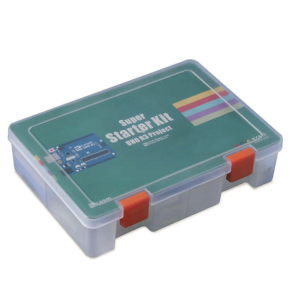
ELEGOO UNO R3 Super Starter Kit Compatible With Arduino IDE
For this Super Starter Kit, Elegoo provide a 24-lesson tutorial, introducing the basic setting of the software IDE, the working principles of the sensors and the simple program to enable the UNO board to control the sensors.
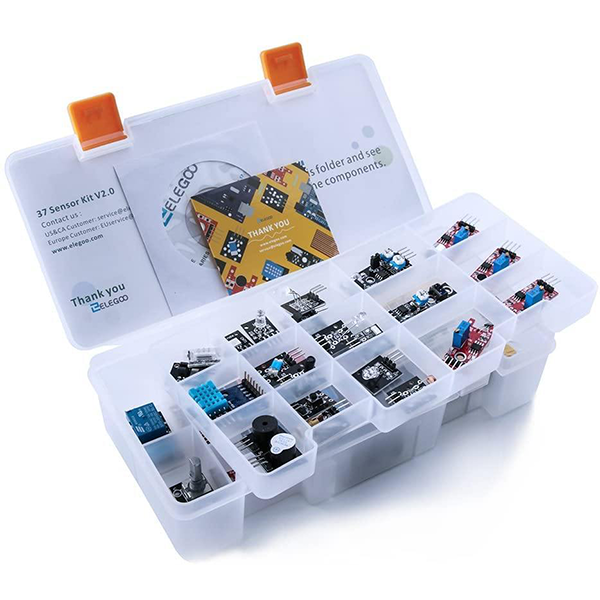
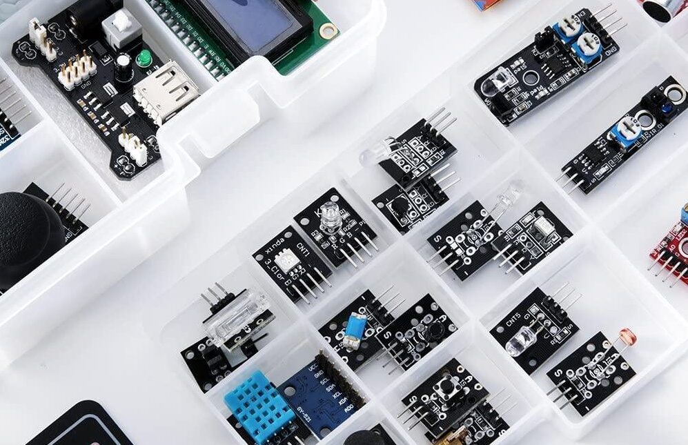
ELEGOO Upgraded 37 In 1 Sensor Modules Kit, Compatible With Arduino IDE
Electronics is not as complicated as you imagine especially with Elegoo 37-in-1 sensor kit. For advanced users like professional lab engineers, electronic major students and experienced hobbyists for starters, they can use this kit to do various kinds of tests and experiments with so many sensors available at hand.
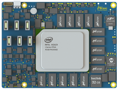
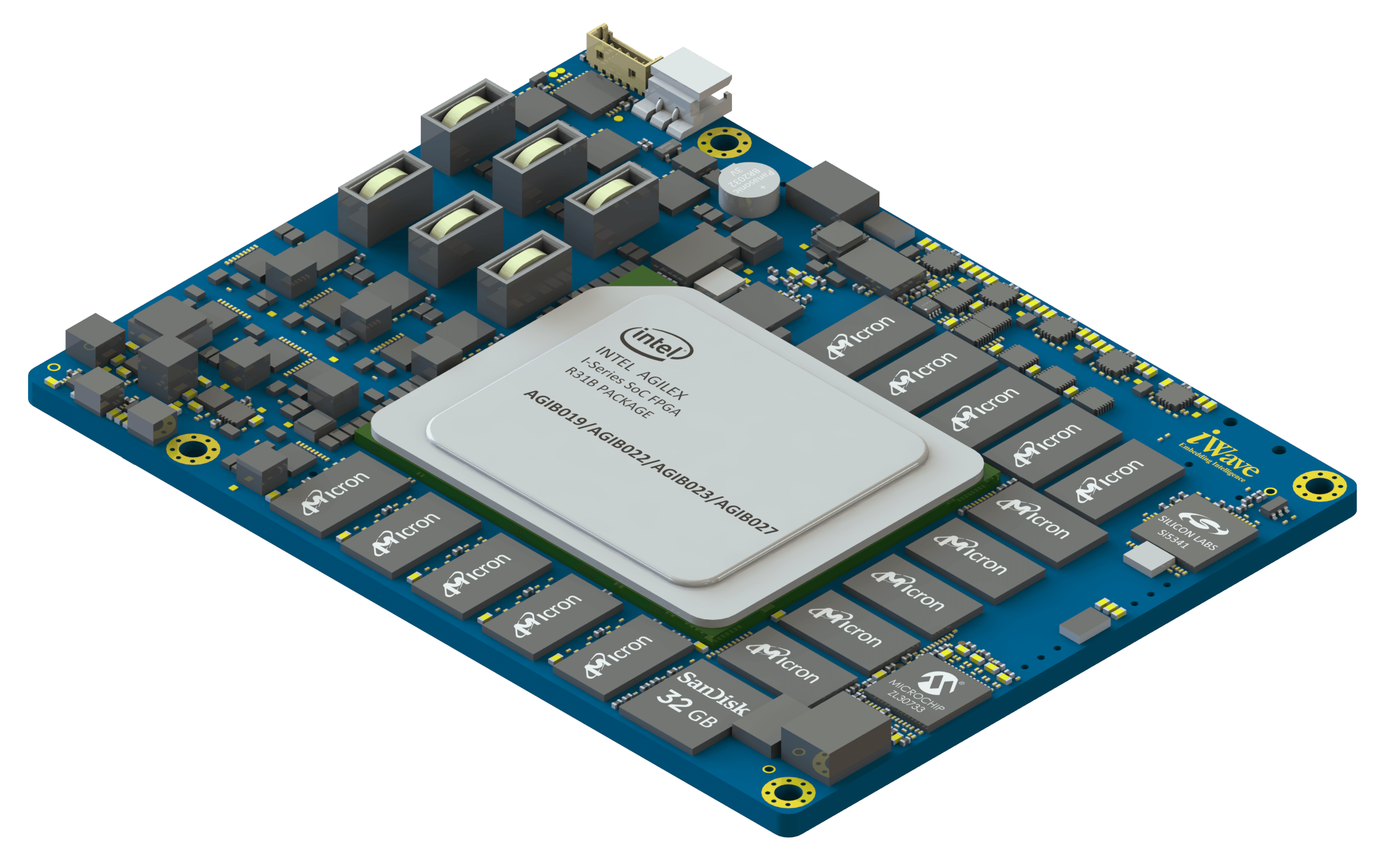
AgilexTM SoC/FPGAs enable customized acceleration and connectivity for a wide range of computing & bandwidth-intensive applications such as data center, networking, and edge applications while providing an improvement in performance with 40% lower power consumption. Furthermore, it delivers 2x fabric performance per watt and integrates the ARM Cortex A53 Core application processor to provide high system integration.
Available in a 120mm x 90mm form factor, The system on modules is the industry first to offer a pin-compatible System on Modules covering a majority of the F-Series and the I-Series.
The AgilexTM System on Module is power-packed with up to 2.7M programmable logic elements for processing huge/complex data algorithms. Besides this, the SoM supports primary interface and components, such as Gigabit Ethernet, USB2.0 port, JTAG, UART, onboard DDR4 and eMMC flash for storage, high-speed transceivers, and more.
Complementing the AgilexTM SoC on-chip resources, the SoM provides for:
Up to 64 FGT transceiver channels (up to 32G NRZ / 58G PAM4)
Up to 8 FHT transceiver channels (up to 58G NRZ / 116G PAM4)
On SoM PTP & SyncE Network Synchronizers
SmartVID to adjust voltage as per the temperature and performance requirements
Up to 138 LVDS/276 SE IOs
“The two new System on Modules featuring the new Intel® AgilexTM SoC are built to enable companies in developing leading-edge computing applications by providing flexible and feature-rich platforms”, said Ahmed Shameem M H, Hardware Project Manager at iWave Systems.” Through the years of remote work and supply chain challenges, a system on module based product approach seems to be the preferred route. iWave has designed these SoMs to suit various applications by including a plethora of interfaces.”
To enable quick prototyping and speed up development, iWave supports customers by providing reference designs in the form of development kits and sophisticated up-to-date software packages.
More information on the iW-RainboW-G43 and iW-RainboW-G51 AgilexTM SoC based System on Modules can be found here.
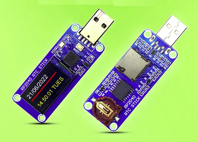
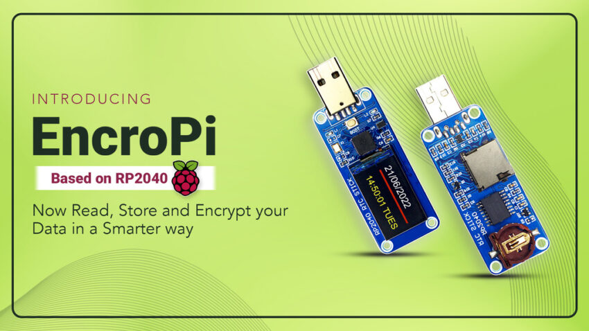
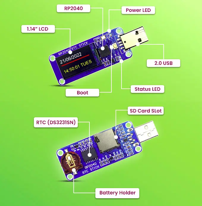
EncroPi is a device that when connected to a system, can be used to log data, encrypt data, or as a secure key, and store the data in real-time. The innovative and highly-efficient USB RTC stick can be used to keep track of seconds, minutes, hours, days, dates, months, years, and even temperature information for designing cutting-edge devices.
“There are so many RTCs available in the market, but our idea was to make it more efficient than just being a real-Time Clock. So we decided to mount it with a strong micro-controller RP2040 and make provisions for data storage. We tested EncroPi on several parameters and created a prototype that solves many issues in one go,” SB Components writes as it talks about the idea behind its invention.
Combined with the power of the low-cost high-performance RP2040 microcontroller, EncroPi is, no doubt, a lightning-fast and extremely reliable product designed to help you in your projects seamlessly. The microcontroller has two ARM Cortex-M0+ cores @ 133 MHz, 264KB SRAM, and large on-chip memory. There’s also a microSD card slot, an onboard display, a coin cell battery holder for RTC devices, and the ability to automatically switch to a backup coin cell supply in the advent of a power outage.
Asides from being a real-time clock for PCs, embedded systems, servers, and other devices that need accurate time keeping, EncroPi can also serve as many other things:
You can use it as a USB data logger to save/store data. You won’t lose your data again and will not have to go through the stress of loading it over and over again every time. There’s a dedicated SD card slot for this purpose.
You can also use it as an encrypted key to secure codes and application sources
EncroPi as a security key provides a seamless authentication experience. Its small and portable size allows for this.
Specifications include:
Raspberry Pi RP2040 dual-core Cortex-M0+ microcontroller @ 133 MHz with 264KB SRAM
IC module DS3231 RTC functions as a clock-setter in the product.
QSPI flash
MicroSD card slot
1x USB 2.0 Type-A or Type-C port
1.14-inch LCD with 240×240 resolution
Onboard boot button to upload the firmware
Power and Status LED
Battery Holder with button cell for power backup of DS321
Separate SD card slot for storing the data you want to run on the device
Power Supply: 5V via USB port
The feature-rich device is a power booster product for electronic hobbyists and time setters. It is also a perfect solution for those who wish to learn more about data logging and make their own encryption algorithms.
EncroPi is widely applicable in IoT applications, medical devices, automation, servers, embedded systems, etc. It can be used as a clock or as an alarm setter in mobile phones, PCs, and laptops, in ECG devices and hearing aids, in office attendance systems, as well as in digital clocks and cameras.
EncroPi was launched on Kickstarter in July and has since surpassed its funding goal of 500 GBP. Rewards include of $43 for the EncroPi with enclosure, $62 for the EncroPi with enclosure and a USB RTC board with enclosure, and $181 for a pack of 5x EncroPi with enclosure.
The company has a Github account and will release the code and samples after the crowdfunding campaign is complete.
Production is scheduled to start by September while shipping will be by November this year.