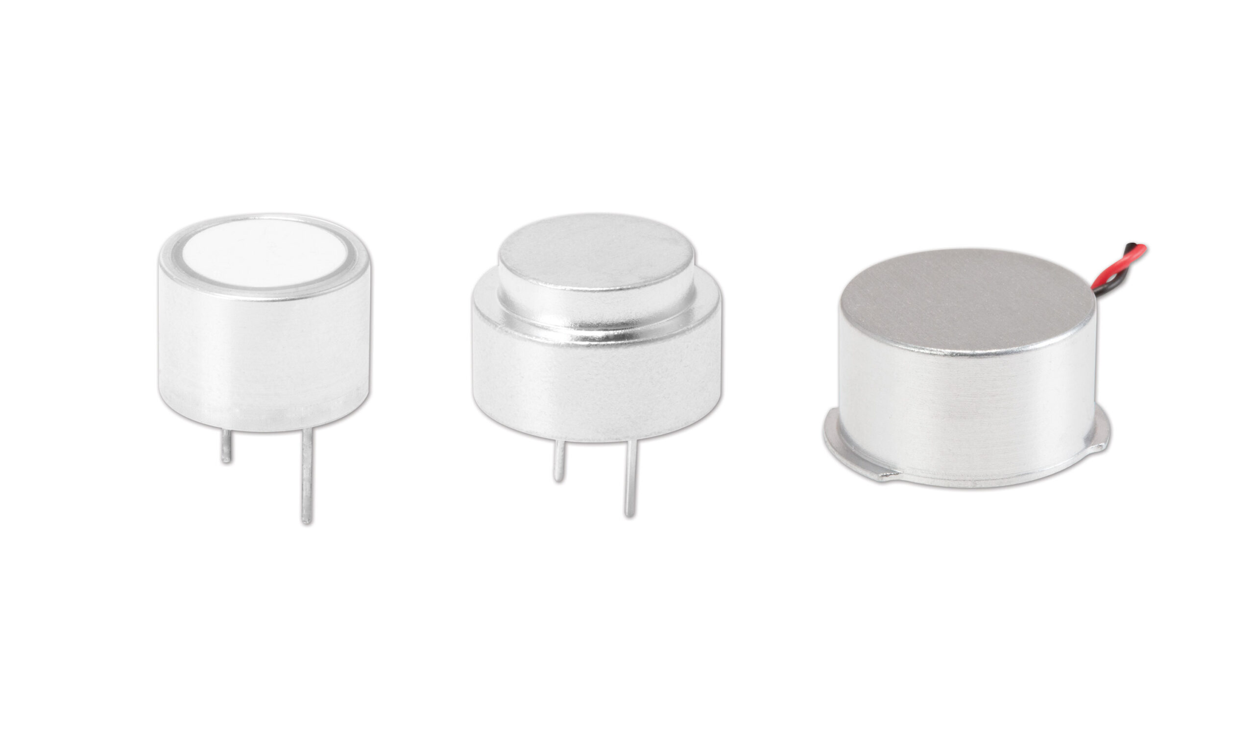
CUI Devices’ Sensors Group today announced the expansion of its ultrasonic sensors product line with a range of new ultrasonic transceiver models. Featuring ingress protection ratings of IP67 or IP68 and high frequency ratings up to 400 kHz, these ultrasonic transceivers boast industry-best lead times and are ideal for applications subject to moisture and environmental contaminants.
Possible users: Ultrasonic sensor applications subject to moisture and contaminants
Primary features: IP67 or IP68 ratings, frequencies up to 400 kHz
Cost: $3.49 per unit at 100 pieces through distribution
The ultrasonic transceiver models carry expanded beam angles from 7 up to 80 degrees, distance ratings from 0.03 up to 15 meters, and operating temperature ranges from -40 up to 85°C. Housed in compact, aluminum cases, these ultrasonic transceivers also offer through hole, wire leads, and wire leads with connector mounting styles. With combined transmit and receive functions in a single package, engineers can benefit from a simplified ultrasonic sensor solution for distance measurement, object detection, and proximity sensing.
CUI Devices’ ultrasonic transceivers are available immediately with prices starting at $3.49 per unit at 100 pieces through distribution. Please contact CUI Devices for OEM pricing.
For helpful resources and tools on ultrasonic sensors, check out our Resource Library which houses a range of blog posts, videos, and more.
Canonical, a privately held company and partner with leading silicon and hardware companies like Advantech and Lenovo, has announced a new version of an operating system for nearly all public cloud workloads and emerging categories of smart gateways, self-driving cars, and advanced robots.
The robust and fully containerized Ubuntu Core 22 from Canonical, optimized for IoT and embedded devices, is now available for download.
“Our goal at Canonical is to provide secure, reliable open-source everywhere – from the development environment to the cloud, down to the edge and to devices,” said Mark Shuttleworth, CEO of Canonical. “With this release, and Ubuntu’s real-time kernel, we are ready to expand the benefits of Ubuntu Core across the entire embedded world,” Mark added
The Ubuntu Core 22 introduces support for real-time computing in robotics and industrial applications. It is aimed at helping manufacturers deal with the challenges of deploying devices on time and within budget.
The company also provides enterprise security support and services to commercial users of the operating system. Customers benefiting from their 10 years of experience with security maintenance of kernel, OS, and application-level code are already feeling satisfied with it. Brad Kehler, COO at KMC Controls had this to say. “KMC Controls‘ range of IoT devices are purpose-built for mission-critical industrial environments. Security is paramount for our customers. We chose Ubuntu Core for its built-in advanced security features and robust over-the-air update framework. Ubuntu Core comes with 10 years of security update commitment which allows us to keep devices secure in the field for their long life. With a proven application enablement framework, our development teams can focus on creating applications that solve business problems.”
The Core 22 can be best described as one that is extremely secure, resilient, and low-touch. Advanced security features include secure boot, full disk encryption, secure recovery, and strict confinement of the OS.
The Ubuntu Core 22 also has:
Validation sets to permit a set of snap revisions to be installed and updated together
Ability to migrate devices from Ubuntu Core 20 to Ubuntu Core 22
Quota groups to set CPU and memory resource limits per grouped snap services
MicroK8s support for an easily deployed, streamlined, embedded Kubernetes experience
Initial MAAS & cloud-init support
Factory reset option to autonomously restore a device to its initial state
Additional information on the Ubuntu Core 22 can be found on the company’s website. Hopefully, we will start seeing a series of blog posts that drives deep into the features of the OS.
Dallas Texas Instruments (TI) has announced a new family of wireless microcontrollers that allows you to quickly and easily add Bluetooth Low Energy (LE) to almost any application. The new SimpleLink CC2340 wireless MCUs offer high-quality RF and power performance backed by expert technical support. With a wide operating temperature range of -40ºC to 125ºC, an increased memory, longer battery life, and a lesser standby current, the MCUs enable broader adoption of BLE technology across many everyday applications such as industrial sensors, medical laboratory devices, and outdoor environments such as EV charges or smart meters.
“I am grateful for the contributions of our membership in delivering innovative solutions that benefit the Bluetooth ecosystem and help broaden the adoption of Bluetooth technology,” says Mark Powell, CEO of the Bluetooth Special Interest Group (SIG). “Industrywide, 5 billion Bluetooth® enabled devices are forecast to ship in 2022. The commitment and involvement of Bluetooth SIG members like Texas Instruments allow Bluetooth technology to meet the growing demands for enhanced wireless connectivity in a wider range of applications.”
The latest addition to the SimpleLink portfolio which provides innovative connectivity solutions to the industrial, automotive and electronics markets, offers connectivity solutions to your design needs.
“The new MCUs will provide high-quality RF and power performance at an affordable price,”
said Marian Kost, TI’s Vice President and General Manager of Connectivity.
Specifications Include:
Flash memory of 256KB for CC2340R2 and 512KB for CC2340R5 (gives exceptional flexibility for engineers and ample space for application code)
36KB of RAM
Standby Current of less than 830 nA (about 40% lower than competing devices; helps extend battery life for up to 10 years on a coin cell battery in wireless applications)
Shelf life of 18 to 24 months
2 weeks of active Bluetooth LE operation on a coin cell battery
Output power range of up to +8 dBm (this is about the highest among competing Bluetooth LE wireless MCUs; allows for expansion of RF performance and connection range)
Has a low power consumption in sleep mode
Has wireless protocol support
Integrated RF balun (allows for a simpler design with fewer external components).
The MCUs are expected to be in volume production in the first half of next year. Pricing for the CC2340 family is said to start at $0.79 which is a relatively low price compared to competing devices. This will make it affordable for engineers and developers to add Bluetooth Low Energy connectivity to more products easily. Other useful details on the Bluetooth LE CC2340 can be found on the product page or the company’s website.
RISC-V, an open-source instruction-set architecture based on RISC instructions is projected to be the architecture of the future. As RISC-V architecture evolves, there is a need for a high-performance RISC-V simulator. MachineWare, a Germany-based startup known for its high-speed instruction set simulators, has unveiled SIM-V, a RISC-V simulator. This simulator allows developers to interactively debug even the most complex designs without requiring actual hardware.
Being MachinWare’s flagship product, SIM-V blends an immensely strong simulation experience with great customizability for every application varying from tiny embedded devices to large supercomputers. This simulator enables developers to test software stacks in real-time including Kernel OS, Java virtual machines or rich graphical environments, and other complex user-space applications. It offers less execution time, saves compute resources, and fosters developers to work fast.
SIM-V Variants
In order to perfectly match the user’s requirements, MachineWare offers two specialized SIM-V variants. The two variants are SIM-V Compute and SIM-V Edge.
SIM-V Compute
SIM-V Compute aims for designing and developing 64bit RISC-V systems. These systems are mainly focused to execute complex software stacks with a rich OS and powerful APIs. This simulator makes it simple to detect hard-to-find bugs and other software issues.
Features of SIM-V Compute:
SIM-V Compute interacts with developer-friendly industry-standard debugging tools in addition to its extensive introspection and debugging capabilities. As a result, a user may readily identify bugs and other security glitches inside the software stack.
It provides smooth operation and an interactive user experience while simulating complex software stacks.
Due to its configurable architecture, a developer may combine different processor designs to develop a multi-core system without degrading the performance.
Integration of SIM-V has become easy with the support of the SystemC TLM-2.0 standard (IEEE 1666-2011).
SIM-V Edge
Small, embedded devices living at the cloud’s edge characterize the modern world. These devices rely on interconnectivity to function effectively but also they are more likely to face security issues. It makes designing and developing a secure 32-bit RISC-V edge computing device convenient.
Features of SIM-V Edge:
With this variant, a developer may quickly interface a wide range of virtual and physical hardware.
A developer can discreetly monitor and track the hardware condition during the operation.
It includes a fault injection mechanism for locating major software defects and security glitches.
The support of SystemC TLM-2.0 standard (IEEE 1666-2011) allows easy integration of SIM-V Edge.
Technologies Powering the High-Performance SIM-V
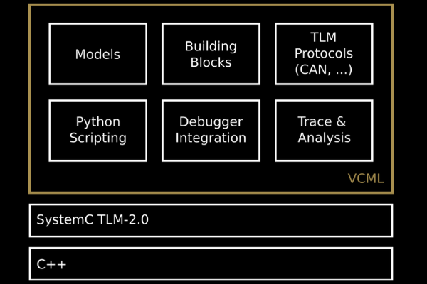
Using MachineWare’s innovative core technology, SIM-V provides maximum performance and seamless model integration. This powerful RISC-V simulator is based on MachineWare’s open-source SystemC modelling library VCML and also the fast and flexible instruction set simulation framework FTL.
VCML (Virtual Components Modeling Library)
VCML is MachineWare’s free and open-source (Apache 2.0) SystemC TLM-2.0 modeling library. It comprises a set of off-the-shelf models for frequently utilized components like buses, memory, timers, and I/O controllers such as Ethernet, PCI/e, and VIRTIO. VCML enables simple integration into current setups and SystemC platform models, with tracing, analysis, and scripting tools.
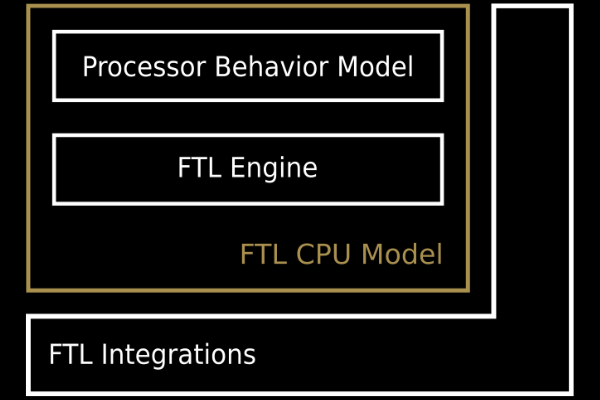
FTL (Fast Translator Library)
FTL is MachineWare’s approach for delivering high-performance, retargetable, and functional Instruction Set Simulators (ISSs). This enables easy customization of the simulator to incorporate custom-tailored RISC-V instruction set extensions or even construct entirely unique instruction set simulators for any microprocessor architecture.
The managing director and co-founder of MachineWare, Lukas Jünger commented on the aim of the robust simulator in a press release
“Our objective is to provide RISC-V software developers with the tools they require to produce safe and secure software stacks on time and without glitches.”
The technologies powering SIM-V makes it one of the high-performance simulator. Coming with a best-in-class high simulation engine along with a rugged architecture, it allows a developer to perform smooth operations. For more information on the library or the SIM-V variants visit the official webpage.
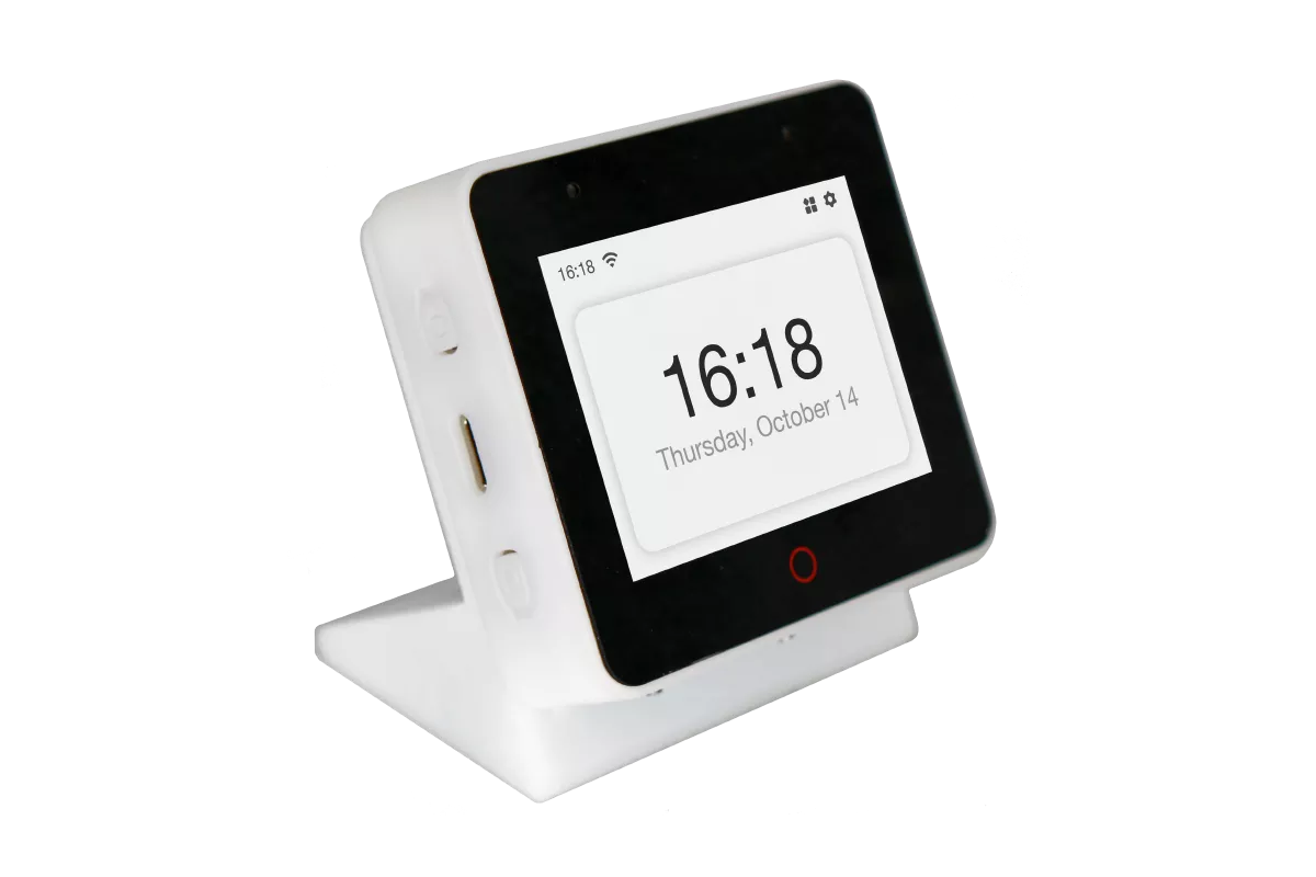
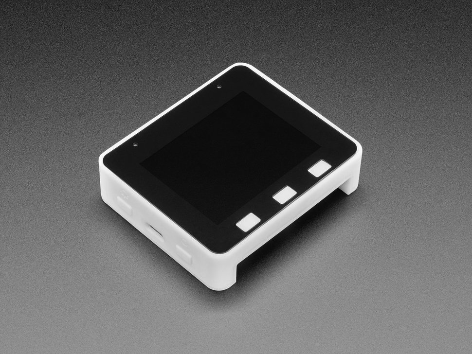
Espressif Systems recently introduced an AI voice development kit built around the ESP32-S3 system-on-chip for monitoring smart IoT devices– ESP32-S3-BOX. The hardware platform has a touch screen controller to provide human-computer interaction that can control various sensors and smart devices. With the increasing adoption of voice assistant-based smart devices to control the surrounding environment, Alexa and Google Home have seen widespread community support. However, the Espressif ESP32-S3-BOX is different from the cloud-native voice services, as the hardware platform has several onboard modules and a rich set of peripherals as well for easy interaction with these smart IoT devices.
As the name suggests, ESP32-S3-BOX is built around Espressif’s in-house ESP32-S3 system-on-chip featuring XTensa LX7 microcontroller clocked with a frequency of 240MHz. The ESP32-S3 SoC comes with integrated 2.4GHz IEEE 802.11b/g/n Wi-Fi and Bluetooth 5 (Low Energy) wireless connectivity. The ESP32-S3 system-on-chip also supports high-speed octal SPI flash storage and PSRAM with configurable data and instruction cache. One of the key highlights of ESP32-S3 is that it has support for vector instruction to provide acceleration for neural network computing and signal processing workloads.
Espressif System ESP32-S3-BOX is capable of running its in-house audio front-end algorithm and ESP-Skainet, an offline voice-assistant SDK, along with the Alexa-for-IoT SDK to provide enhanced offline and online voice functionalities. Espressif audio front-end algorithm is a high-performance audio algorithm to enable voice user interface and provide the flexibility to build low-cost voice-assisted applications. The software algorithm is recognized by Amazon as a “Software Audio Front-End” solution for Alexa built-in devices. The voice-optimized solution can comfortably operate with ESP32-S3.
Three key features delivered by the Espressif audio front-end algorithms are acoustic echo cancellation, blind source separation, and noise suppression. The acoustic echo cancellation is designed to remove echoes from the audio input through a microphone. The blind source separation algorithm uses multiple microphones to detect the direction of the coming audio which helps in improving the quality of desired audio source in a noisy environment. The noise suppression algorithm works on a single-channel audio signal to eliminate unwanted non-human noise to improve the audio signal that needs to be processed.
Another key software functionality that ESP32-S3-BOX is designed with is the ESP-Skainet, an intelligent voice assistant that supports the Wake Word Engine and Speech Commands Recognition. Espressif wakes word engine, WakeNet is designed to provide high performance and a low memory footprint wake word detection algorithm for users. This will give IoT devices the ability to always wait for wake words. On the other hand, Espressif’s speech command recognition model, MultiNet, is designed to provide flexible offline speech commands to smart IoT devices. The model allows the user to easily add custom speech commands to eliminate the need to train the model again.
ESP RainMaker, a complete system to build AIoT products with minimum coding, is also available on the ESP32-S3-BOX and can be used to configure GPIOs and offline commands to provide control via phone applications or voice assistants. Apart from the flagship ESP32-S3-BOX, the manufacturers have also launched another simplified version of the AI voice development kit, ESP32-S3-BOX-Lite. The hardware platform is very similar but without the capacitive touch panel and mute buttons. In addition, the ESP32-S3-BOX-Lite comes with three function buttons that can be customized by the user.
The manufacturer has provided all technical resources, including hardware reference design and user guides for public availability. The hardware platform can also be purchased on Amazon for US-based customers, and AliExpress and Adafruit for the rest of the world.
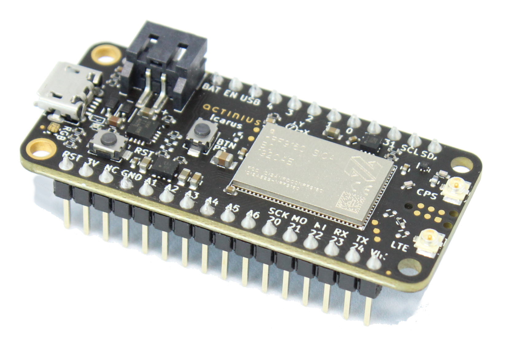
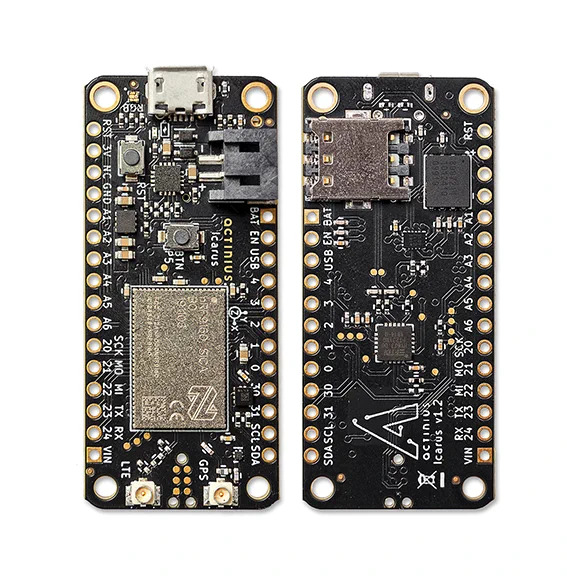
Amsterdam-based embedded device manufacturer Actinius has launched a cost-effective cellular IoT board in a feather wing form factor, Icarus, built around the Nordic Semi nRF9160 modem and combines LTE-M and NB-IoT connectivity. Adafruit Feather boards have been very popular due to their small form factor and community support. There have been several other manufacturers other than Adafruit who decided to develop their custom development boards in the same form factor. Actinius Icarus comes with eSIM options for internet data right out of the box and a nano-SIM connector, which is very rare in the developing IoT ecosystem.
Actinius Icarus, as mentioned earlier, is based on the Nordic Semi nRF9160 modem, which is a low-power system-in-package that comes with wide-range connectivity. The Nordic Semi nRF9160 SiP features an Arm Cortex-M33 application processor, which is responsible for running different workloads. Full-modem SiP is an energy-efficient solution for cellular IoT applications supporting both LTE-M and NB-IoT. The application processor is equipped with 1MB of flash storage and 256kB of memory, making the application development seamless on a single device. The incorporated Arm CryptoCell security features offer cryptographic and security resources to protect the IoT application from various attack threats.
There also comes a low-power 3-axis accelerometer, general-purpose button, RBG LED, battery charging and measurement. The board supports various serial communication protocols, including I2C, UART, SPI, and I2C with EasyDMA. There are 18 GPIOs and up to 6x 12-bit ADC and up to 4x PWM units. The Actinius Icarus can be powered using multiple power sources, including LiPo charging with MPPT, and power headers. Importantly, the hardware platform does not come with an antenna and a uFL LTE antenna which is required to connect to a cellular network.
Features of Actinius Icarus IoT Board:
Cellular connectivity: As a cellular IoT board, the Actinius Icarus needs to support various connectivity options, and the hardware platform does not fail to do so. Actinius Icarus supports NB-IoT and LTE Cat-M1 global coverage.
Multiple power sources: There are multiple power sources the board supports. The LiPo battery gives the flexibility to be deployed in critical remote IoT applications.
Free LTE-M and NB-IoT data: The board includes an eSIM with 10MB of free data for three months for the developer to get started with the board. After the trial period, the developer can choose to get a subscription on Actinius.io or get a nano-SIM.
Software capabilities: Icarus IoT board will be packaged with the pre-programmed latest modem firmware from Nordic. MCUboot, a secure bootloader for 32-bit microcontrollers, provides options for uploading the firmware to the board using a USB port and Actinius programmer application. The MCUBoot can also be used in combination with Zephyr RTOS on the nRF9160 SiP. Another software support that comes along with the cellular IoT board is the Actinius Asset Tracker Application Firmware, which can transmit data such as accelerometer, battery, and GPS data.
If you are interested in more information, consider visiting the official product page where you can purchase the hardware for €112,95 excluding VAT. The manufacturer has also provided detailed documentation to get started with Actinius Icarus IoT board.
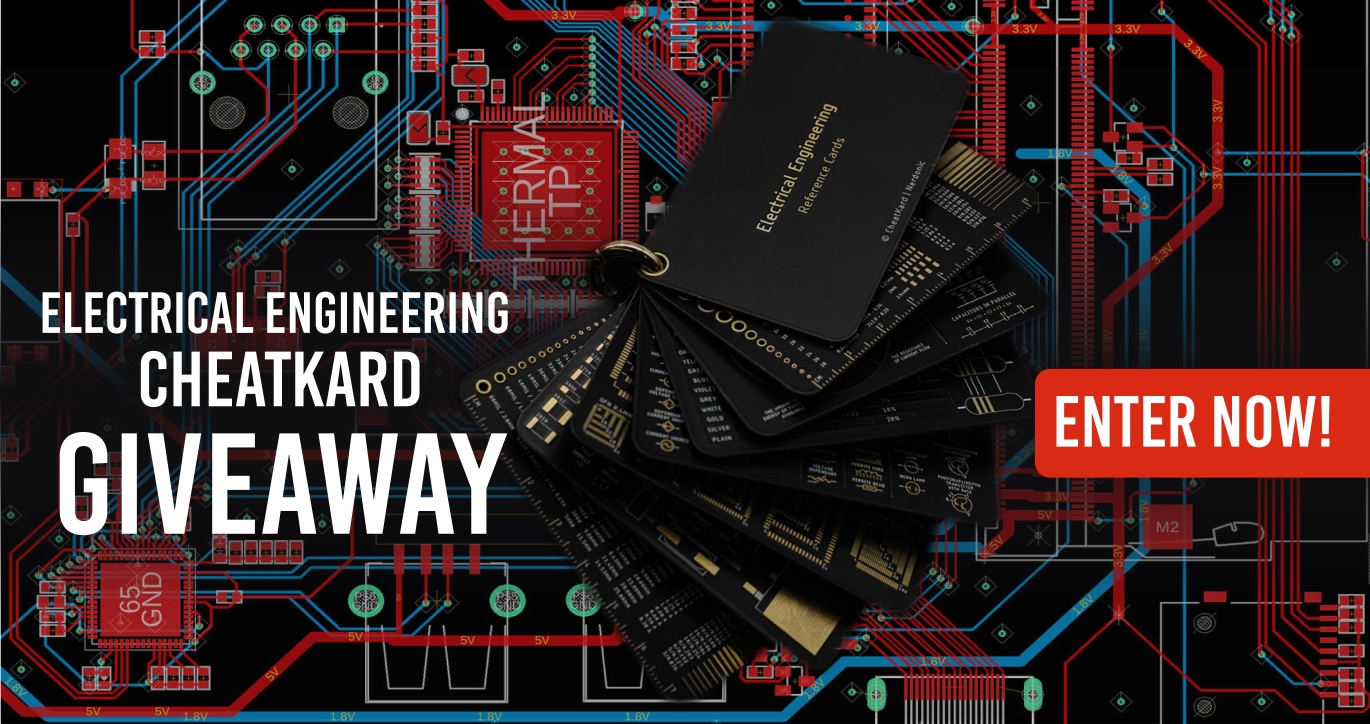
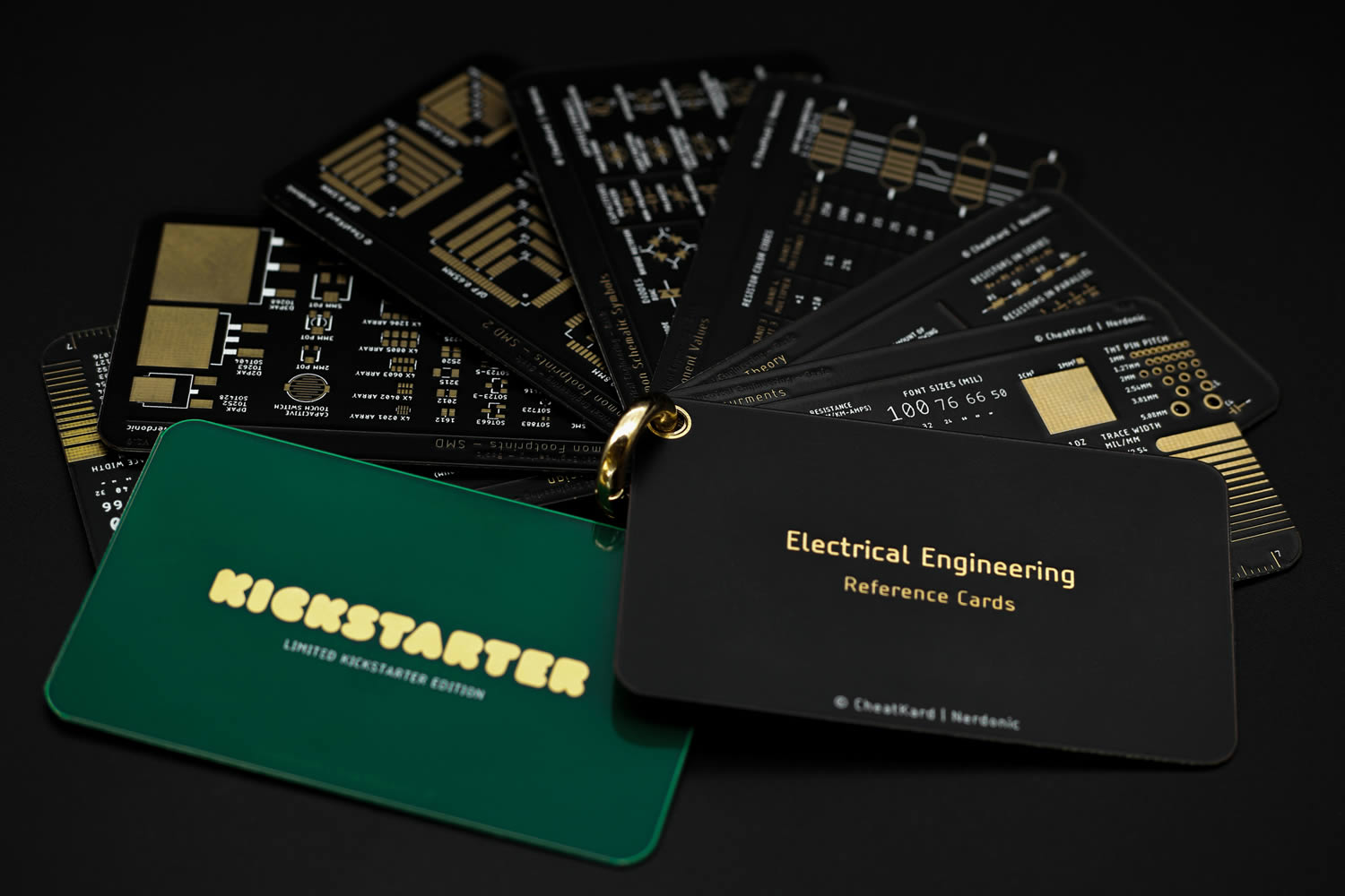
I’m definitely not the only one that thinks PCB rulers are awesome. I grab one every chance I get, events, gift bags, etc., and I may have too many of them right now, but don’t blame me, they carry those minute but important information and drastically reduce the time you spend “Googling” or flipping the pages of that EE text. So you will probably understand my skepticism, mixed with curiosity when I came across the CheatKard by Nerdonic, and the claims of it being better than the ruler, and boy was I surprised. It has quickly become a tool I think everyone should have and we will be giving away 3 units, yup, for free. More details at the end of the article.
Launched via a crowdfunding campaign on Kickstarter last year, The CheatKard is arguably the most concise electrical electronics engineering quick reference tool out there. It features Measurement references,Schematic Symbols, SMD Footprints, Laws & Theory, PCB design reference helps, and a Component value calculator, amongst others, all packed on gold plated cards no bigger than a credit card and bonded together by a key ring.
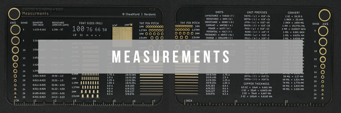
Measurement references
For measurements, the CheatKard has 16+ measurement references that help you quickly check and determine things like AWG wire gauge/diameter/electrical resistance, Font sizes, Surface mount (SMD) pin pitch gauge, Through-hole (THT) pin pitch gauge, 1mm/1cm square, trace width/amp gauge, PCB copper thickness Electrical/Number/Units conversion, and perform regular measurements (CM & INCH), among others.
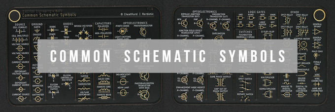
100+ Schematics symbols
The same wide range of cheats and quick lookups exists for different aspects of electronics design, with diverse component symbols, their PCB footprints, and diverse other information that come in handy during board design. CheatKard has 100+ Schematics symbols for diverse types of Power Sources, Ground, Diodes, Resistors, Capacitors, Inductors, Optoelectronics Components, Transistors, Transformers, Logic Gates, Relays, Opamps, Motors, Crystal Oscillators, etc., and lookup cheats to quickly and easily determine their values/ratings, especially for components like resistors and capacitors.
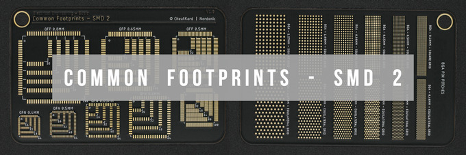
PCB Footprints
If you, like me, sometimes forget what physical size the SMD component size description numbers actually translate to (especially the old, rarely used ones) when designing PCBs, then you are in luck, as the Footprint card on CheatKard comes with an exhaustive list (132+) and physical representation of different types of footprints, from BGA to SOT23, SOIC to MicroMELF, TSOP and various variations amongst others.
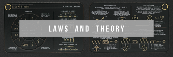
Laws and Theory
The feeling I get with the CheatKard is a tool that is useful for everyone (the professionals, the Nerds, and Tech heads, as well as the hobbyists and DIYers) at every stage of electronics design/engineering, you have dimensions you have schematics symbols, you have footprints, PCB design references, and last but not the least, Laws and theory. Yeah, I know you may never forget ohms or Kirchoff’s (or Coulombs. Lenz’s, Faraday’s, and others covered by CheatKard) laws, but you got to agree that sometimes there is a skip, and it is nice to get to them without having to whip out your phone to Google or start flipping the pages of that giant EE reference book.
To learn more about the Cheatkard, you can check out the crowdfunding released on Kickstarter.
Now to the giveaway. As mentioned earlier, we will be giving away 3 x Cheatkards to three lucky users, well just because they are awesome and so are we, and all you need to do to participate and win is to drop a comment stating what tiny electronics design reference you always struggle to remember. Let’s see how many people are in the same shoes as you!
ENTER NOW -> Just leave a comment below and we will randomly select 3 comments to win the Cheatkards
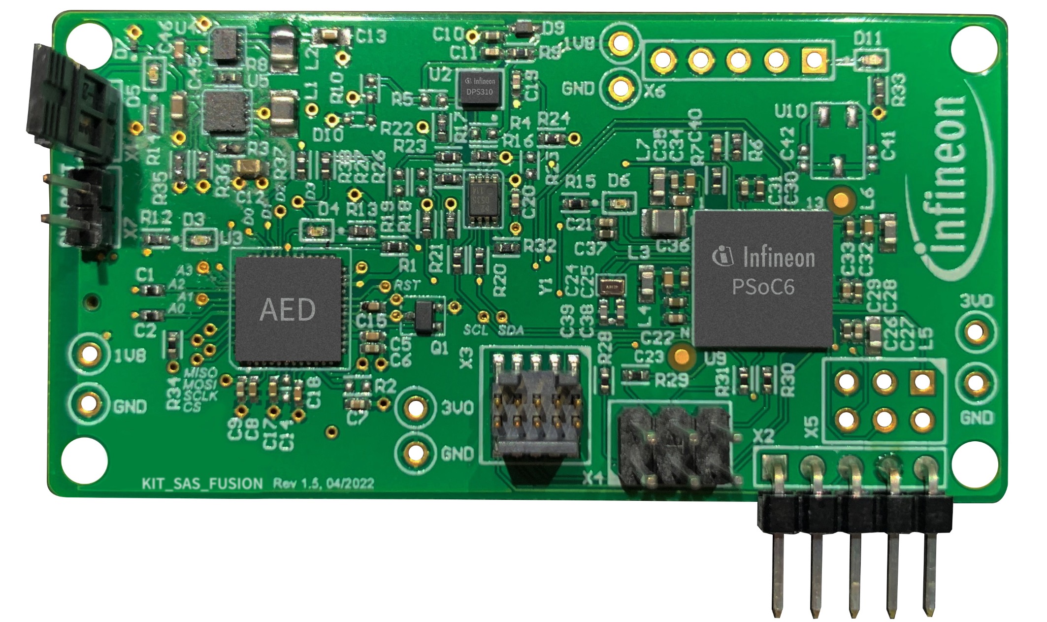
We recently witnessed the market position of Infineon in the embedded systems with the integration of its CYW43439 wireless chip into the very famous Pico family, Raspberry Pi Pico W microcontroller board. The company recently announced a battery-powered Smart Alarm System, which is a sensor fusion based on artificial intelligence and machine learning. The technology of low-power wake-on acoustic event detection provides high performance for smart builds and homes while achieving greater battery life compared to complex IoT solutions.
Infineon’s advanced security system is based on the company’s sensor fusion powered by the PSoC and XENSIV sensors. The combined technology of Infineon’s multi-layered security system that uses XENSIV microphones and XENSIV barometric pressure sensor with acoustic event detection provides the sensor fusion algorithms running on PSoC a protection and monitoring features against burglary and intruders.
“We are excited to enable a unique and differentiated approach to bring AI/ML capabilities to cost-sensitive, battery-powered home security sensor systems, without sacrificing battery life,” said Laurent Remont, Vice President of IoT and Sensor Solutions at Infineon’s Power & Sensor Systems Division.
The home alarm system needs to be robust and should not be triggered by other household sounds or background noises to avoid false alarms. Infineon Smart Alarm System supports three events that the technology can protect against– glass breaks, intruders, smoke detectors, and carbon monoxide detectors. For all the specific applications, the system is capable of understanding the intensities in the frequency spectrum, avoiding false alarms and providing greater accuracy.
The proposed alarm system incorporates the company’s signal-to-noise ratio analog XENSIV MEMS microphone, XENSIV digital pressure sensor, and a PSoC 62 microcontroller. The system also provides sensor fusion algorithms used to precisely train tinyML models to combine acoustic and pressure sensor data for accurate detection. With increased accuracy, AI models are able to eliminate background sounds that usually generate false positives.
“Current home security solutions are unreliable for detecting events such as glass breaks. Our new solution combines a number of best-in-class technologies to create an alarm system that is smart, reliable and power-efficient. We look forward to bringing more innovative solutions into the home security market.”
Alarm system reference design technology is available today, while the board will be available later this fall starting in September 2022.
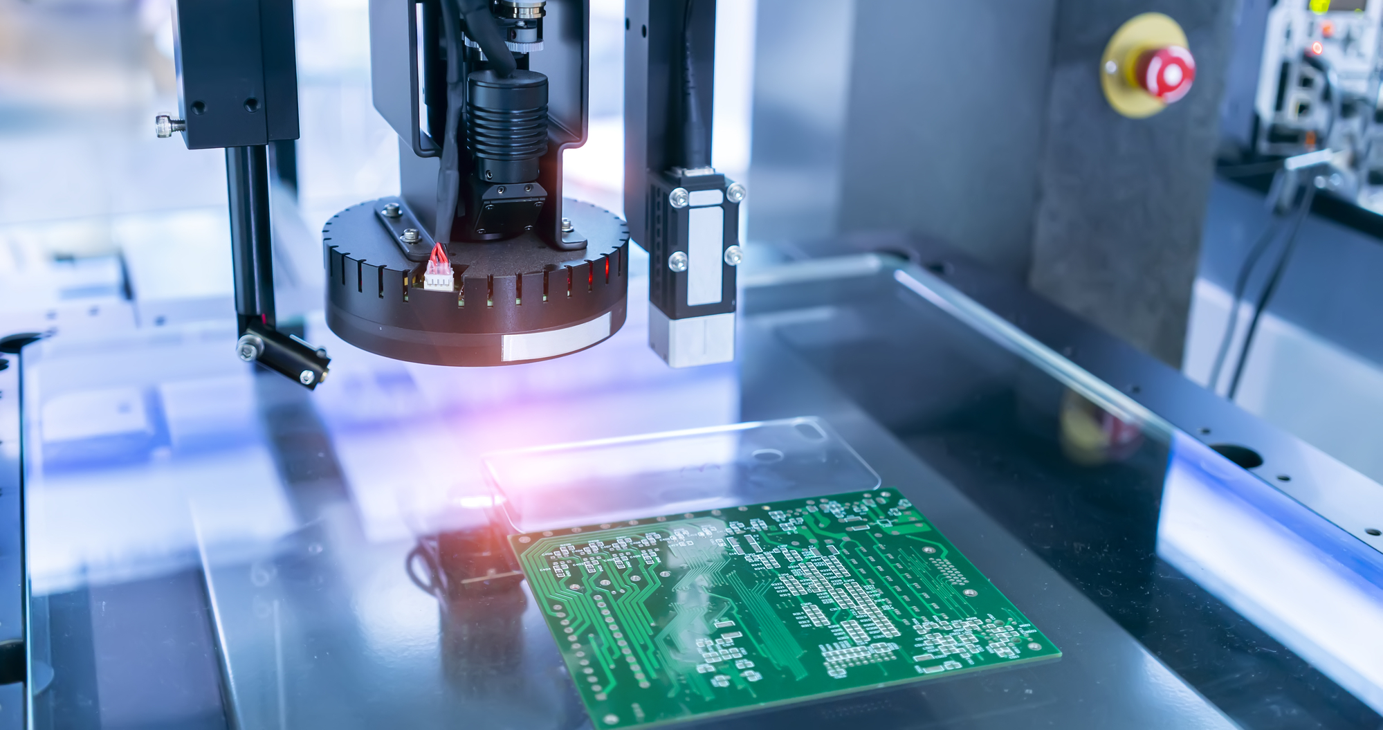
JLCPCB for faster electronics manufacturing, carrying out its new standard PCB assembly service as an ace project created by JLCPCB, has been committed to reducing PCB assembly costs, improving ordering experience, speed up SMT lead-time, therefore, it gives the hand for professional electronics engineers to focus on their electronics business which allows industrial companies to manufacture high-quality electronics product.
Although the SMT project of JLCPCB was officially launched in 2019, the foundation of the entire project started in 2006, and it has been stable for 16 years. JLCPCB is good at summarizing SMT industry standards. The components angle is an industry problem that plagues SMT. JLCPCB was one of the first companies to stand out and popularize the standard. The latest IPC-7351C may also adopt this standard.
The electronics industry people involved getting to say “…”
Procurement staff: I can’t source complete parts
Electronics Engineers: JLCPCB helps me to save time and cost. I have more time available for validating scenarios.
Factory workers: Entire production line will arrange orders on the production line efficiently.
Entrepreneur: JLCPCB helps me to improve my business through time and cost-saving
How does the Global Parts Sourcing service greatly save time and money?
Building up parts lib by JLCPCB parts pre-order service (launched in 2021) and parts global sourcing service (launched in 2022) is PCB assembly technology innovation. Welding of more than 100 pieces has always been painful and difficult for the PCB manufacturing industry, this causes chip manufacturers to be unwilling or refused to provide such services for various reasons. JLCPCB pioneer another shortcut invests huge sums of money, and creatively adopts no replacement individual feeder models to cure SMT sample production pain. Sufficient-components SMT service for JLCPCB’s new and forward-looking global parts sourcing service is on its self-developed and one-stop platform build up supply amid the global parts shortage problem which allows people to prepare parts in advance. Knowing
there is a keen demand for components hinders the industry’s development. JLCPCB launches a global sourcing service in order to expand the parts supplying source for our customers, such a decision will provide customers with high-quality authentic components more stably, allowing them to achieve self-sufficiency on the JLCPCB SMT platform.
Compare to buy-as-you-go mode, pre-order parts allow people to get a favorable price. Pre-order service adopts real-time quotation service, and the price is transparent and open. JLCPCB does not earn any price difference, and also implements a policy of multiple refunds and multiple supplements for pre-purchased components. Customers can purchase on-demand without worrying about the loss of payment due to the failure of the pre-order service. JLCPCB is able to obtain more low-cost but high-quality parts from reliable global parts suppliers. And we know that component agents or original components will have corresponding purchase prices. In order to protect
their own interests, MOQ is a common method used by component suppliers. The bargaining power of JLCPCB can help small and medium-sized enterprises or individual customers reduce cost risks, collect various component needs, and negotiate prices with trusted component suppliers
first to obtain more favorable prices and to save customers money and effort.
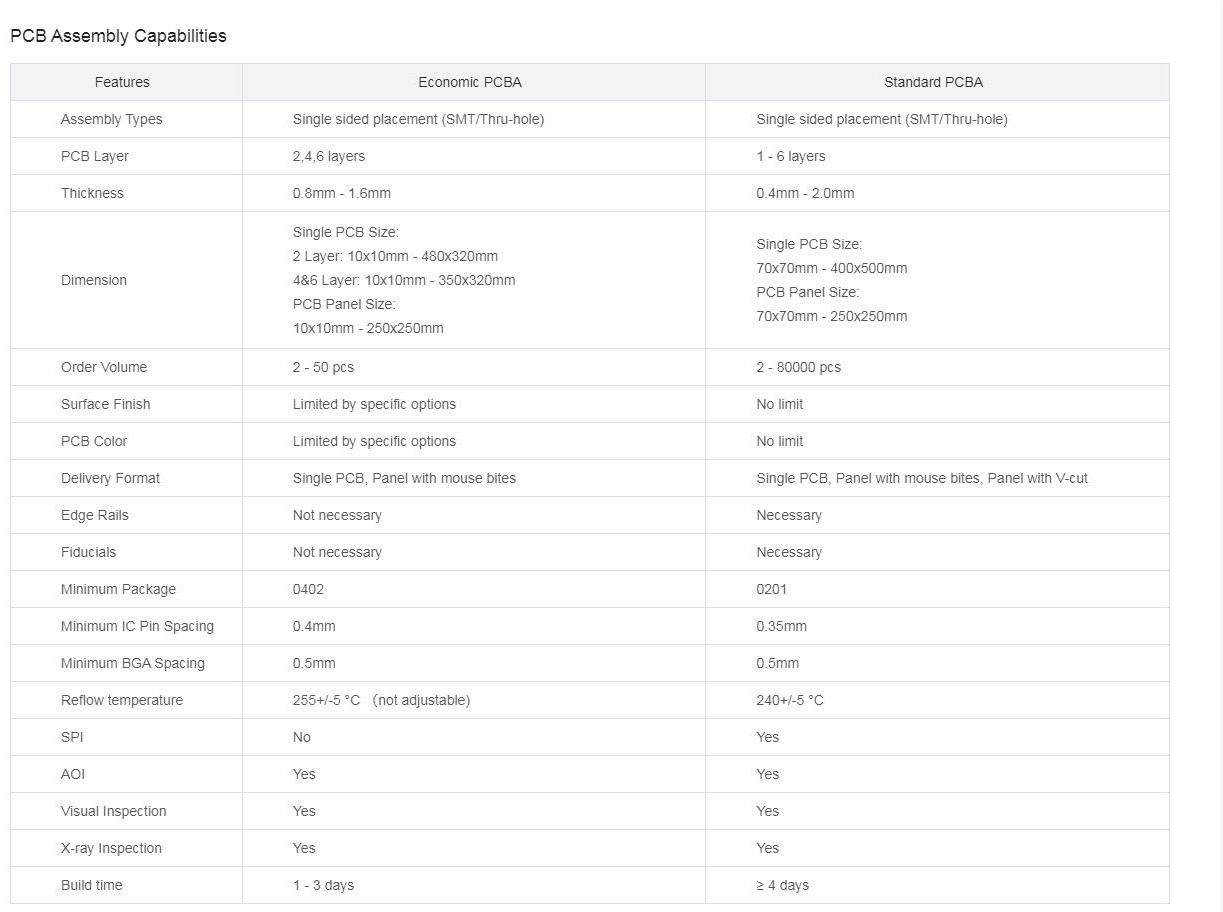
What’s the newest 1-6 layer double-side Assembly
JLCPCB newest standard PCB assembly service allows SMT batch production and double-sides soldering of boards (patch + plug-in). No limit on PCB quantity, no limit on PCB process, no limit on parts kinds, V -cut panelization.
Standard PCBA service is more cost-effective
Assembly fee: $0.0017 per joint
Setup fee:$8 (JLCPCB $54 New User coupon free your setup fee)
Stencil Fee: Free
Example: There are 5 boards that require SMT, each with 200 solder joints, total: 10 solder joints assembly fee + Setup fee:$8 + $0 Stencil Fee
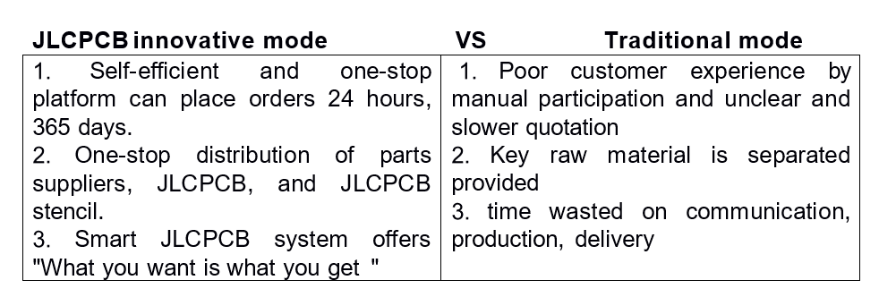
Standardized independent online ordering mode, real-time quotation of patch order, real-time display of patch effect, what you see is what you get, and short ordering process that you can master safely. In this era, disturbing users as little as possible in the pursuit of a good product.
Why is JLCPCB Standard PCBA Service faster easier cheaper?
JLCPCB integrated 4 major departments to improve SMT at full speed The 4: PCB, component, the stencil, and SMT are in the same industrial zone. Compare to other companies, JLCPCB transfer components, stencils, and SMT expressly, saving a lot of time through the AGV in the zone.
In order to ensure the most extreme SMT experience, JLCPCB Group also established a special working team for SMT lead-time and packaging in mid-March 2022. All businesses must take SMT as the highest priority.
JLCPCB Economic PCBA
JLCPCB Standard PCBA:
Quality-assured Standard PCBA service is faster and easier
The PCB stencil components are all self-operated, and they are all in the same production zone. This is the cornerstone to ensuring the quality, delivery time, and price of JLCPCB Assembly. Meanwhile by streamlining the entire process from ordering, parts sourcing and PCBA prototyping, you can get your products in hands as fast as one week. Allowing you to iterate, improve
and deliver on time or even faster:
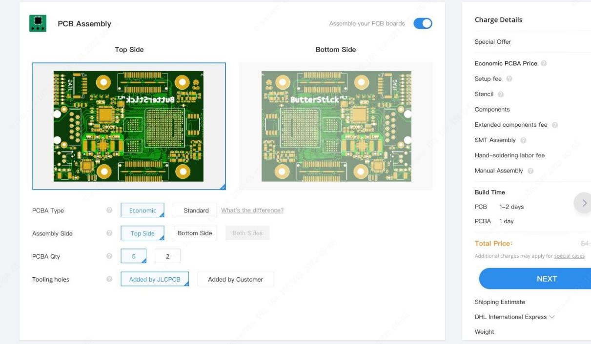
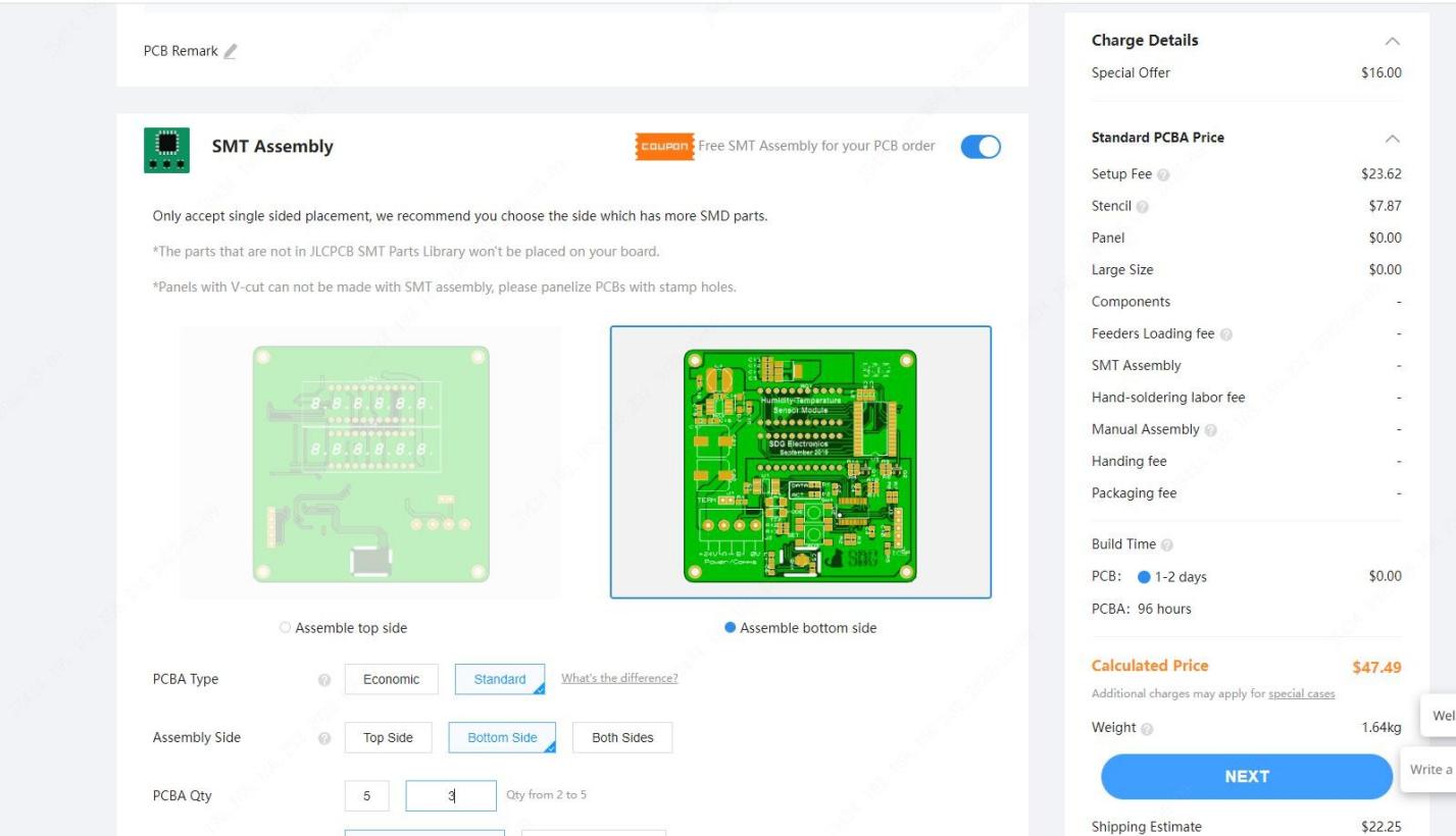
Easier Ordering for Standard PCBA
Ordering process:
Place an order for PCB (circuit board)
Place an SMT (SMD) order
Payment
Production
QC
Shipping
What materials do you need to prepare?
Components: You don’t need to provide it, JLCPCB provides the required components
PCB (Circuit Board): Use PCB order
What documents do you need to prepare? GERBER+BOM+CPL
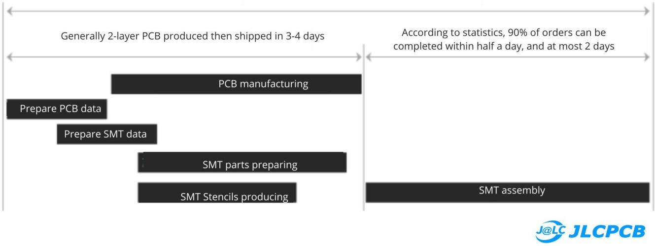
90% of SMT orders only take half a day of production
We deeply think about the effectiveness of our offered services, that’s why every single second counts, because the faster we go the more effective we become, through this equation, we could offer more reliable service to our customers. So we started thinking about the execution of the simultaneous task while producing the PCBs Assembly supporting lines are also getting ready simultaneously, such as components preparing, SMT stencils preparing. So, the overall construction period becomes shorter.
The following figure exemplifies the construction period of a 2-layer board:
Free $54 New User Coupon for Standard PCBA with 10M+ parts
Free $54 New User Coupon offered
Standard PCB Assembly supports double-side soldering, and unlimited quantity, order as many as you want
JLCPCB SMT Parts Library 200k+ in-stock components (689 Basic components and 200k+ Extended components); and 10M+ global parts
10M+ parts from reliable parts suppliers worldwide
Parts Pre-Order service from Global Reliable Parts Suppliers
Build Personal library Inventory, Save parts for current or future orders
How does JLCPCB keep Superior SMT quality by 6 self-operated industrial zones?
JLCPCB owns 6 Self-operated factories with high-end equipment quality process double-sided patch with plug-in wave soldering. Advanced Yamaha automatic placement machines and all equipped with electric mast, 10 temperature zone lead-free reflow soldering, automatic printing machine, mature and reliable management team, and self-developed supporting software. All LDI production equipment is used, with high precision, and there will be no line offset and assembly welding alignment offset. The four-layer board adopts LDI equipment, and the double-layer board adopts LDI+ automatic exposure machine equipment. JLCPCB only uses A-grade raw material
board, and never adopts less cloth, high filler, and non-flame retardant board. JLCPCB 4-layer PCB are all made of grade A-boards from real Taiwan Nanya and KB material, with real materials, and the price is around $72 / ㎡ ; The double-sided panels are all made of “true A-grade” boards, around $45.74 / ㎡.
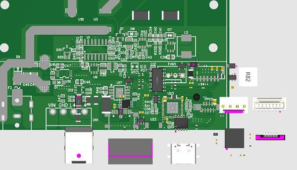
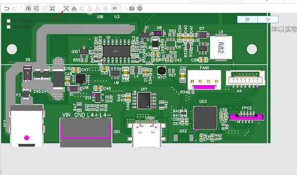
“What you see is what you get” by free DFM checking
JLCPCB Free DFM file Checking offered a 3D simulation map of physical objects. After manual matching, you can see the patch effect from what you see and what you get. And one key Get a $54 New User Coupon. A special value-added service with a $24 SMT coupon every month.
After the matching, we will output a report (PDF can be exported in the upper right corner). Customers can use this PDF report for their project documentation and then they can determine the components that JLCPCB does not have and the components that can be pasted. Purchasing staff can search for missing materials offline and this will accelerate the process.
One-click alignment to solve the problem of components deviating from the pad. Due to incorrect automatic data processing or mismatch of component polarity, the loaded components sometimes deviate from the pad Taiyuan. At this time, manual adjustment is very time-consuming. In order to solve this problem, we provide a one-click adjustment:
For example, your design looks:
Press the Auto-Align button on the toolbar to automatically align all components:
Does JLC PCB Assembly make progress in the Electronics Industry?
Absolutely! JLCPCB PCB Assembly sincerely helps electronics engineers stay healthy. Manual welding is time-consuming and labor-intensive, with a high error rate, and is the number one killer of health, lung disease, and blindness. You should quickly order from who will help you solder common components, and let your PCBA boards are ready to use, in an industrial-grade quality.JLCPCB Standard PCB Assembly service produces PCBA in double sides (patch + plug-in). You can get assembled boards as quickly as 7 days. The standard PCBA production line equipment is also adjusted, such as automatic solder paste printing machine, SPI (solder paste inspection), AOI, and other equipment to better ensure product quality which helps the electronic industry and electronic business make progress. Get 54 New User Coupon to redeem a unique double-side PCBA journey now!
The Octal numbering system is another digital numbering system that uses the Base-8 system like the previously discussed Hexadecimal numbering system having the Base-16 system. The Oct- is a combining form used as a prefix meaning “eight” and that is why Base-8 (eight) system is termed an Octal numbering system. Likewise the Hexadecimal number, the octal numbering system reduces the size of an equivalent large binary number and makes it convenient to read and write to the original large binary number.
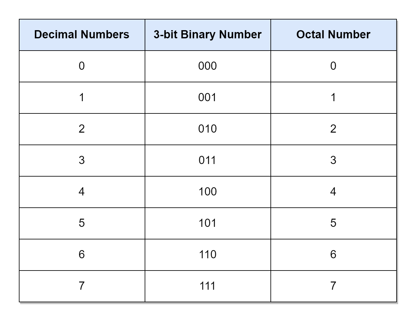
A numbering system’s digit has a range of numbers that it can use to express its value. This range is dependent on the base value of the numbering system i.e. Base-10 (decimal), Base-16 (Hexadecimal), or Base-8 (Octal), etc. For example, Base-10 and Base-16 systems have ranges of “10” and “16” numbers, respectively. Similarly, Base-8 (Octal) numbering system has a range of only “8” numbers from “0” to “7” i.e. 0, 1, 2, 3, 4, 5, 6, and 7. The octal numbers have only eight (8) distinct values for each digit and each digit has a weight of eight (8) starting from the least significant digit (LSD). In order to accommodate and express “8” numbers in binary, only three (3) bits are required. Following this, the octal values (0, 1, 2, 3, 4, 5, 6, and 7) corresponds to binary equivalent values (000, 001, 010, 011, 100, 101, 110, and 111), respectively.
The octal number is formed by grouping binary numbers in sets of 3-bits. It follows the same procedure adopted, previously, in the Hexadecimal article. However, in Hexadecimal numbers, a binary number was segregated into groups of 4-bits (as Base-16 uses the “0” to “15” range and requires 4-bits). The Octal numbering system is simple compared to the Hexadecimal numbering system as it uses only numbers compared to Hexadecimal using numbers plus alphabets. Moreover, it has only eight “8” distinct values compared to Hexadecimal’s sixteen “16” distinct values. In the early era of digital computing, the octal numbering system was very famous as digital inputs (D0 to D7) and outputs (Q0 to Q7) were in counts of eight (8). However, with the increase in the number of digital inputs and outputs, system architecture and memory size, etc. the hexadecimal numbering system has become more convenient for representing large binary values.
Representation of an Octal Number
The octal numbering system uses the Base-8 system and, as such, an octal number is represented by a subscript “8”. For example, the (1428) is identified as an octal number as it has a subscript of “8”. Further, it is noticeable that each digit of an octal number has a value between 0 and 7. For example, an octal number (1288) is wrong as its least significant digit (LSD) has a value of “8”. Which does not belong to the octal numbering range rather it belongs to the decimal or hexadecimal numbering system. So, a number can be identified to be correct by checking its base value and whether the number of each digit falls within its base range.
Octal Numbers
The following table lists the decimal numbers from 0 to 7 against their equivalents in binary and octal numbers.
Counting in Octal
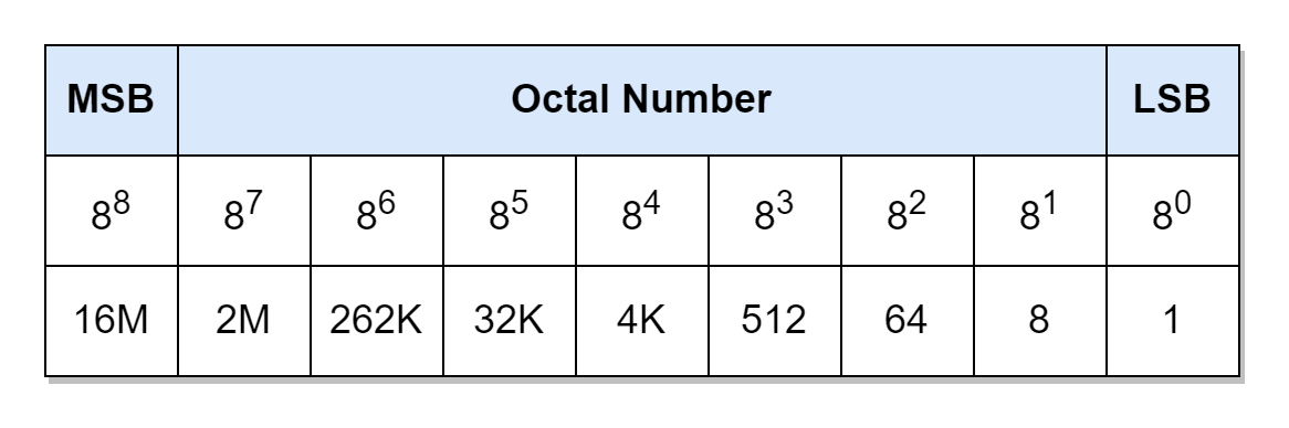
Each digit of the octal number has a weight of eight (8) starting from the least significant digit. The weight of each digit increases by the power of eight moving from least significant digit to most significant digit. The equivalent weight in decimal of each octal digit, up to the 7th digit, is given.
The octal digit has a number range from “0 to “7” and, for counting above this range, another octal digit is added to the left. The addition of the second digit leads to the counting up to (778) which is, in decimal, equivalent to (6310). So, two octal digits can count up to 63. Similarly, a three-digit octal number can count up to (7778) which gives a counting range up to (51110) in decimal.
Addition of 0’s to a Binary Number
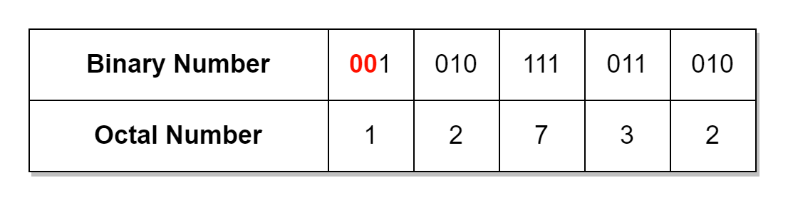
As the binary number is split into 3-bit groups in order to determine its equivalent octal number. This requires a binary number consisting of bits that are multiples of three (3) e.g. 3, 6, 9, 12, and 15, etc. However, this may not be the case when dealing with binary numbers and binary numbers can vary in bit lengths. The solution is to start splitting binary numbers, in groups of 3-bits, from the least significant bit (LSB). In case, the bits of the binary number are not equally divided amongst 3-bit groups then we will be left with less than 3-bits at the end. The leading zeros are added to leftover bits in order to extend their length up to 3-bits. This last group of 3-bits constitutes the most significant digit (MSD) of octal number. In the following table, a non-standard 13-bit binary number (1 0101 1101 101010) is converted to a 15-bit (divisible by 3) binary number by adding leading zeros, and then its equivalent octal number is determined.
In the above example, a 13-bit number requires 2-bits having zero values to be added to the left-most side in order to make it a 15-bit binary number. Similarly, an 11-bit binary number would require one (1) zero bit to be added. The usage of octal numbers reduces the length of binary numbers by three (3) times.
Octal to Decimal Conversion
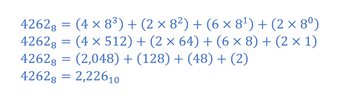
The conversion of octal to decimal value is achieved by using the weighted sum of digits method described in the previous articles. In the following example, an octal number (42628) is converted to a decimal number.
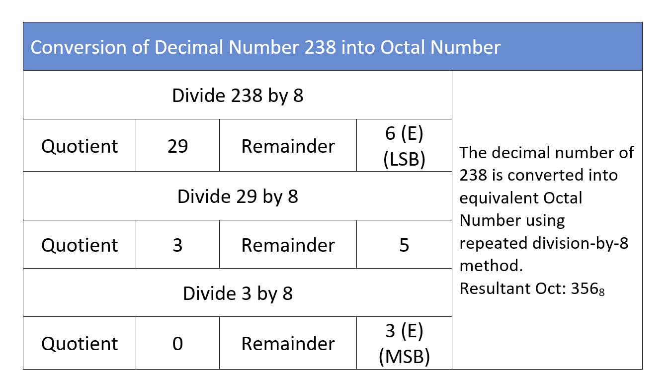
Decimal to Octal Conversion
The conversion from decimal to octal requires the application of the repeated-division-by-8 method. The same method was used to convert a decimal number to its equivalent binary and hexadecimal values in the previous articles. The decimal number (23810) is, hereby again, used to obtain its equivalent octal number in the following example.
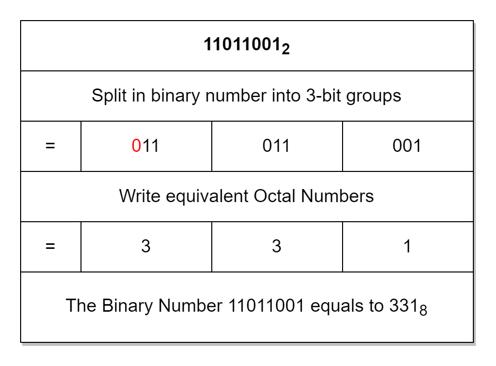
Binary to Octal Conversion Example
The conversion of an 8-bit binary number (110110012) to an octal number is illustrated below.
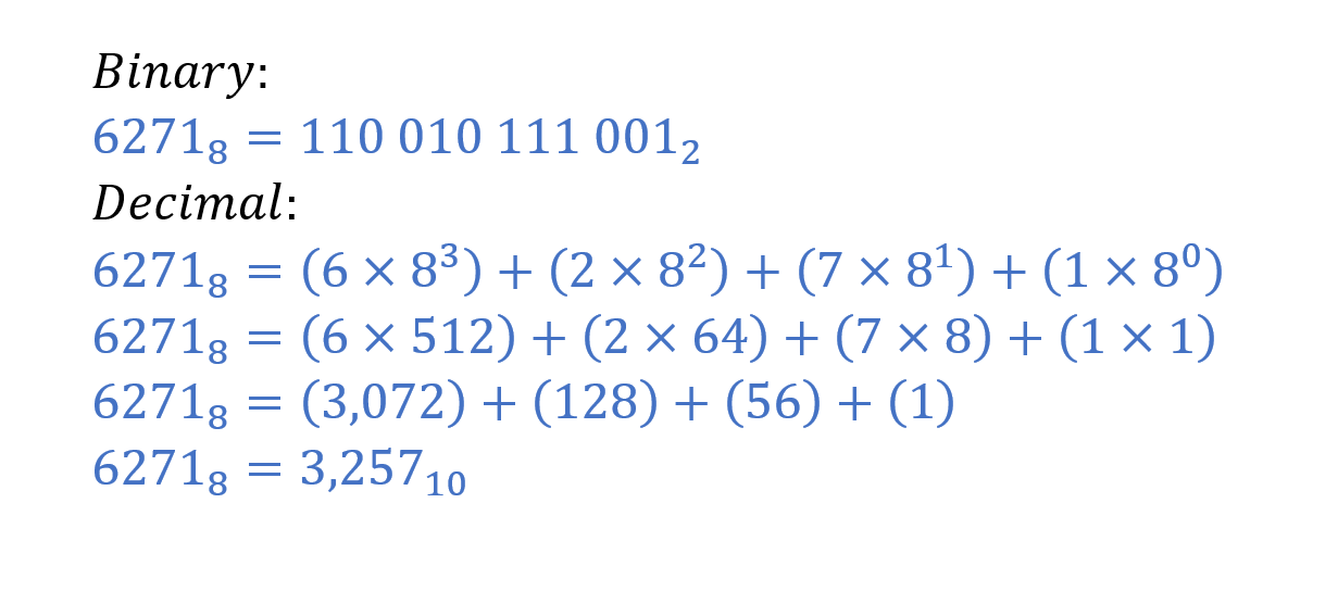
Octal to Binary and Decimal Conversion Example
The conversion of (62718) to its equivalent binary and the decimal number is illustrated below as an example.
Conclusion
The Octal number uses a base-8 system and each digit’s value ranges from 0 to 7 i.e. eight (8) numbers.
In an Octal number, each digit is a group or set of 3 bits. The equivalent of a binary number in octal is obtained by splitting the binary number into 3-bit groups and an equivalent Octal value from “0” to “7” is assigned to each group.
The binary numbers may require the addition of leading zeros on the left most (most significant) side in order to form 3-bit groups.
The Octal number is represented by using “8” as a subscript e.g. 7358.
The Octal number can be converted to a decimal number by using the weighted sum of digits method.
The conversion from decimal to octal requires the application of the repeated-division-by-8 method.
The Octal number reduces the length of its equivalent binary number by a factor of three (3). However, octal numbers are seldom used now, and, as previously discussed, the hexadecimal numbering system has taken its place.