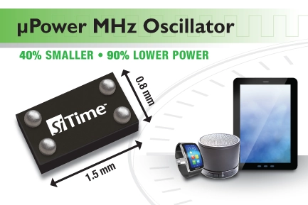
SiTime’s ultra-small micropower 1 MHz to 26 MHz oscillators are ideal for battery-powered mobile, wearable, and IoT devices
SiTime‘s SiT8021 oscillator is 90% lower in power consumption and 40% smaller in size than quartz oscillators. The unmatched combination of ultra-low power, an ultra-small package, and a customizable frequency range make this device ideal for power-sensitive and space-constrained applications.
Features
Ultra-low power: 60 µA
Custom frequencies: programmable from 1.000000 MHz to 26.000000 MHz
Tiny footprint: 1.5 mm x 0.8 mm
Programmable output drive strength provides EMI reduction or the ability to drive multiple loads
Fast lead time
Extended battery life
An optimal choice for best system performance
Smaller PCB
BOM and space savings
Reduces inventory overhead and mitigates shortage risks
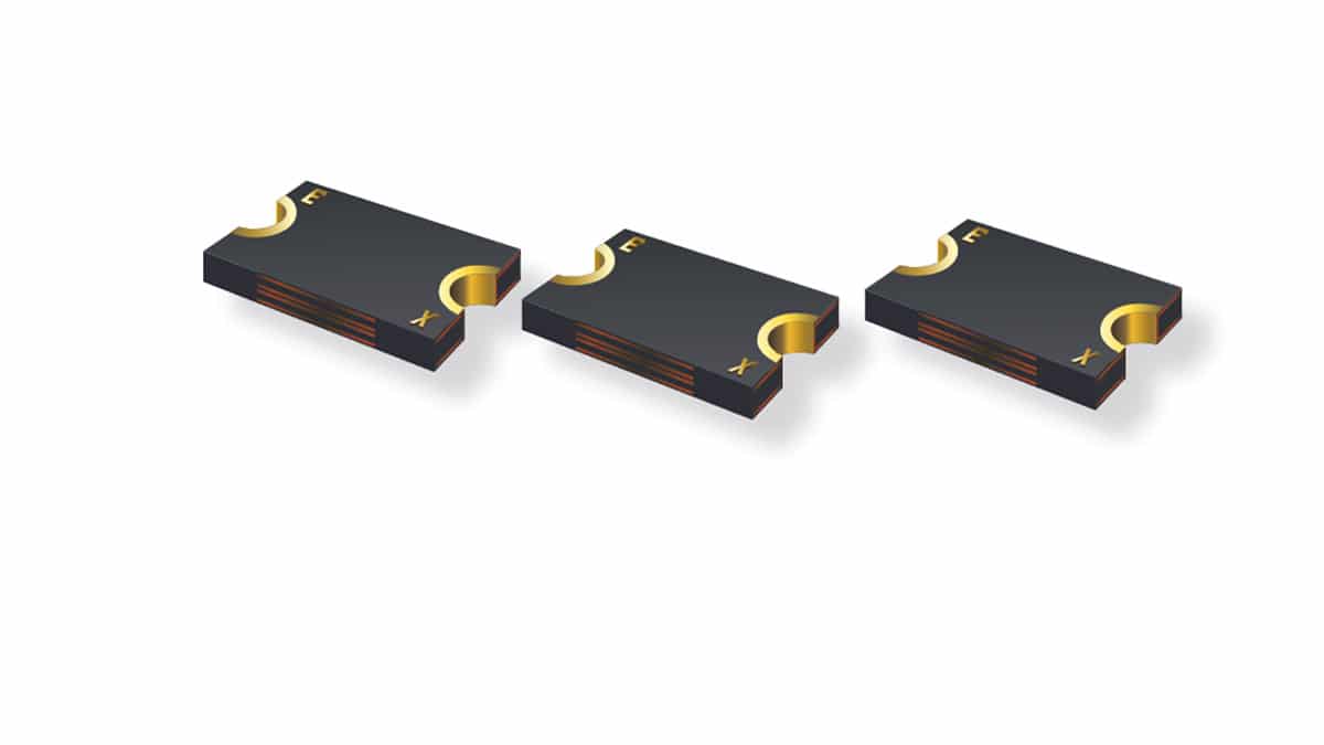
Bourns’ high-power surface-mount PPTC resettable fuses expand the hold current range to 0.75 A ~ 6.0 A
Bourns’ Multifuse® product line expands its model MF-LSMF series high-power surface-mount polymeric positive temperature coefficient (PPTC) resettable fuses. These models expand the hold current range to 0.75 A ~ 6.0 A with maximum voltages of 6 VDC ~ 33 VDC and 20 additional options available.
The MF-LSMF model family utilizes Bourns’ innovative freeXpansion™ design to increase the performance of the resettable fuse with higher hold currents (Ihold), higher voltages (Vmax), improved resistance stability, and smaller footprints. The primary applications for these products include Li-ion battery packs, low voltage telecom equipment, motherboards, and portable consumer electronics protection. These devices have been designed to protect against both overcurrent and overtemperature events within the designated product specifications.
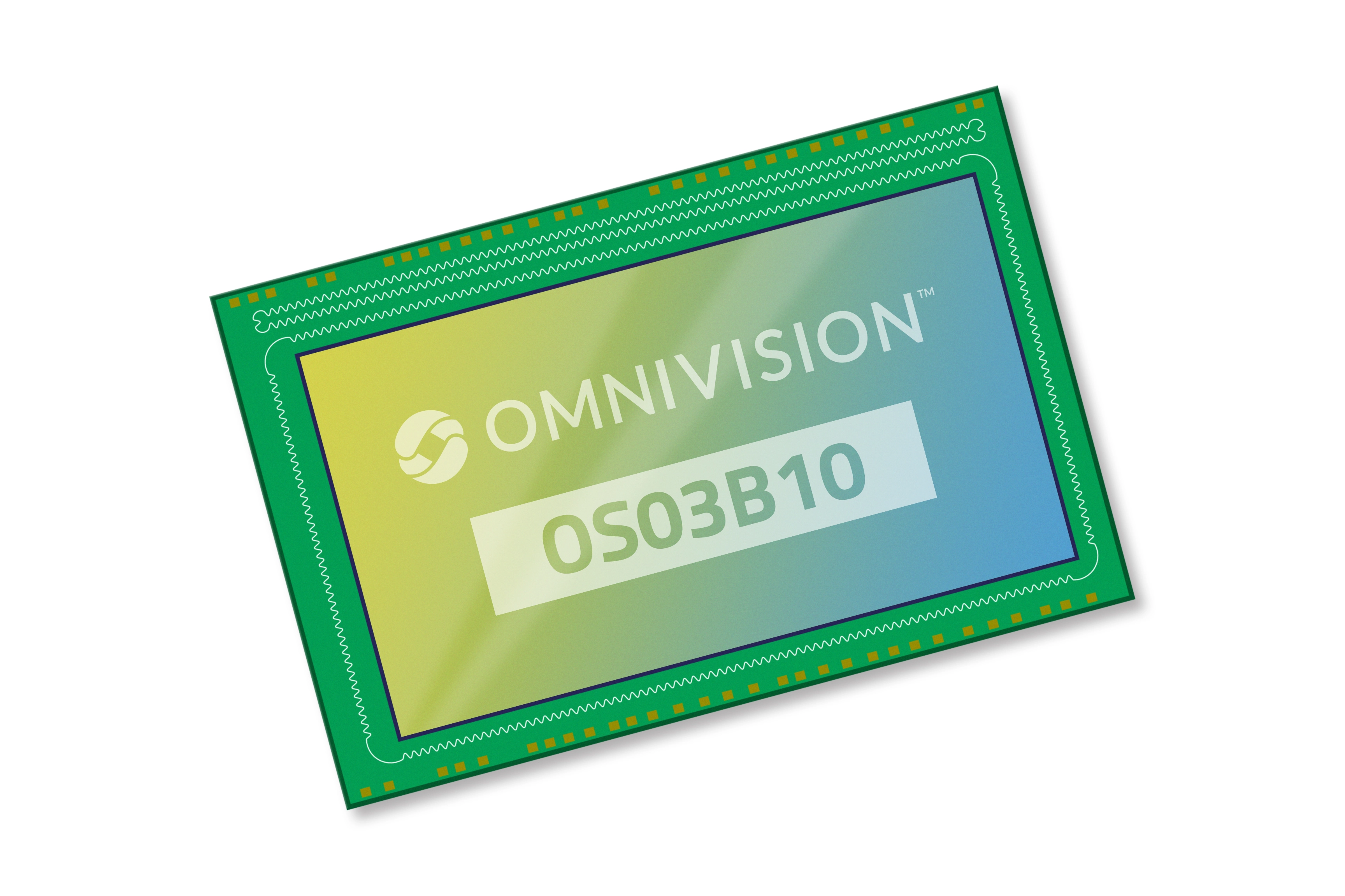
Omnivision’s OS03B10 3-MP image sensor with DVP and MIPI interface support brings high-quality images to security, IP, and HD cameras.
Omnivision has introduced the OS03B10 3-megapixel (MP) 1/2.7-inch optical format CMOS image sensor for security surveillance, IP, and HD analog cameras. Designed to deliver high-quality images and video, the OS03B10 image sensor features a 2.5-µm pixel that is based on the company’s OmniPixel 3-HS technology. It uses high-sensitivity frontside illumination (FSI) for “true-to-life color reproduction” in both bright and dark conditions.
The advanced 2.5-µm pixel architecture also enables the OS03B10 to provide excellent low-light sensitivity, signal-to-noise ratio, full-well capacity, quantum efficiency, and low-power consumption, said Omnivision.
The 3-MP image sensor can capture videos in a 16:9 format at 30 frames per second. It offers default and programmable modes that control parameters such as frame size, exposure time, and gain value. It also offers image control functions such as mirror and flip, windowing, auto black level calibration, defective pixel correction, and black sun cancellation as well as supports DVP and MIPI interfaces.
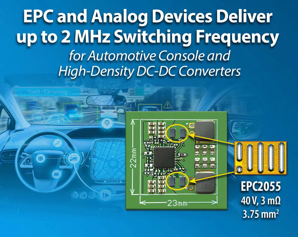
EPC’s EPC9160 9 V to 24 V to dual output 5 V/3.3 V synchronous buck converter reference design
EPC’s EPC9160 is a 9 V to 24 V to dual output 5 V/3.3 V, 15 A synchronous buck converter operating at 2 MHz switching frequency. The EPC9160 features the EPC2055 GaN FET and LTC7890 two-phase analog buck controller with integrated gate drivers from Analog Devices.
The efficiency of the EPC9160 is greater than 93% for 5 V output and 24 V input and, thanks to the high switching frequency, the converter size is very small at only 23 mm x 22 mm for both outputs and an inductor height of only 3 mm.
Applications
Synchronous buck DC/DC converters
Automotive consoles
Power systems require a small size and very thin profile: computing, industrial, consumer, and telecom power
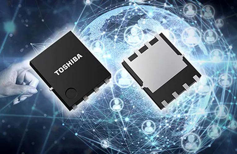
Toshiba has launched a 150V N-channel power MOSFET “TPH9R00CQH” that uses the latest generation process, “U-MOSX-H,” and that is suitable for use in switching power supplies for industrial equipment – including those deployed in data centers and communications base stations. Shipments start today.
TPH9R00CQH has a drain-source On-resistance about 42% lower than TPH1500CNH, a 150V product that uses the current generation process, U-MOSⅧ-H. Optimization of the new MOSFET’s structure has improved the trade-off between the drain-source On-resistance and two charge characteristics, realizing excellent low-loss characteristics. In addition, spike voltage between the drain and source at switching operation is reduced, helping to lower electromagnetic interference (EMI) in switching power supplies. Two types of surface mount packages are available: SOP Advance and the more popular SOP Advance(N).
Features
Excellent low-loss characteristics.
(trade-off between On-resistance and gate switch charge and output charge)
Toshiba also offers tools that support circuit design for switching power supplies. Alongside the G0 SPICE model, which can verify the circuit function in a short time, the highly accurate G2 SPICE models, which accurately reproduce transient characteristics, are now available.
Toshiba will expand its lineup of power MOSFETs that improve equipment power supply efficiency by cutting losses, helping to reduce power consumption.
All motherboards are equipped with a CMOS battery. In the past, it was necessary to maintain the operation of the CMOS memory, which was responsible for storing BIOS data and other parameters of a personal computer. Previously, BIOS settings were stored in CMOS memory which was powered by an independent power source like batteries. With the advent of non-volatile memory, the need for the battery charge disappeared. But why do motherboards still come with CMOS batteries?
What does the CMOS battery do?
Just like regular watches need batteries to constantly maintain time, the computer’s internal clock also needs a constant power source. In addition, many older laptops use CMOS batteries to power the memory chip, which stores configuration settings like boot priority from a specific media, power saving mode, memory status, display type, keyboard settings, and other settings.
Like all other batteries, CMOS batteries also discharge over time. The average battery life is 5-7 years, but this value may vary depending on the manufacturer of a particular battery, battery capacity, and the operating environment of the computer.
How to tell if the battery on the motherboard is dead?
There are several signs by which you can easily determine that there is no power or if your battery will run out of power soon. Different laptops may have different symptoms and this is based on the manufacturer’s diagnostics protocol. Here are the most common signs of a dead motherboard battery:
The first sign that indicates no power is a constant reset of the time and date. The BIOS is responsible for maintaining time, and the value is stored on a special chip on the motherboard. This micro-circuit is powered by a battery and therefore if there is not enough energy to power it, then the computer will reset the time and date during every boot cycle.
The second sign is the constant reset of BIOS settings. The computer will reset the boot order and other settings.
The third symptom is non-functioning apps. Some apps need to sync up with the server in the cloud to function and incorrect time won’t allow the sync to happen.
Fourth sign. The computer won’t start at all. However, this mostly applies to older motherboards. Pay attention to the beeps or flashing LEDs that can be decoded through the factory service manual.
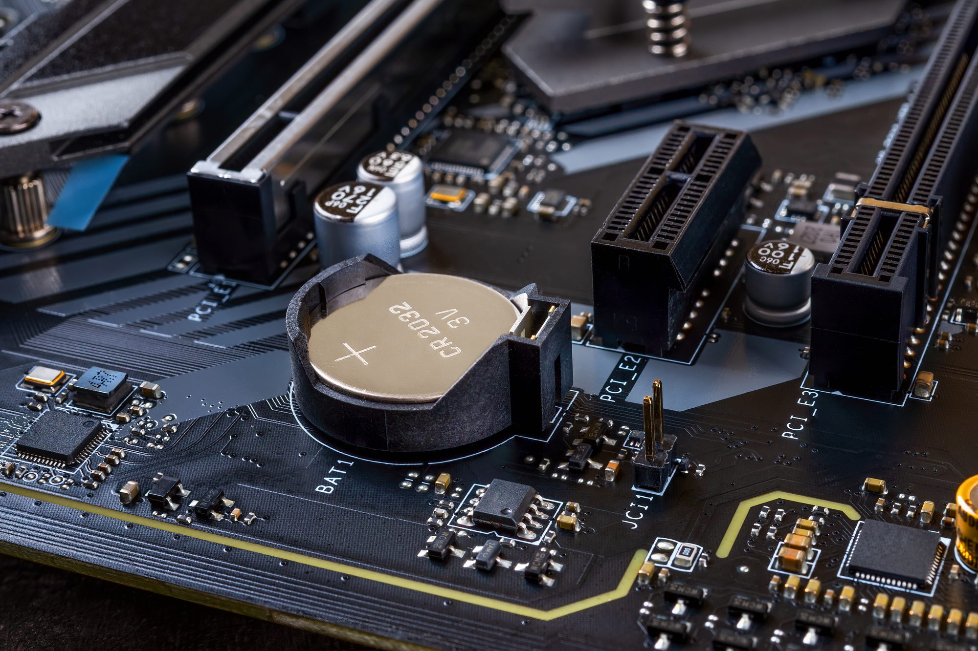
Where is the CMOS battery located?
The location of the battery on the motherboard may vary depending on the manufacturer of the device, but it is almost always easy to visually identify it due to its shape and color. A typical coin-cell battery has a round shape with a diameter of around 2 cm and a metallic silver color. In some laptops, the battery is sealed inside an insulating protective film which can be black, yellow, blue, or any other color. The battery can be located near the CMOS chip or relocated to a different place on the motherboard via wires. On some boards, the battery may have a non-standard shape or multiple smaller batteries merged to form a bigger battery. Some batteries have a plastic holding container that is inserted or even soldered onto the board. In some laptop models, it can be very difficult for an ordinary user to get to the battery since it requires a complete disassembly of the device. A service manual can be checked beforehand to determine the location of the battery and the replacement procedure.
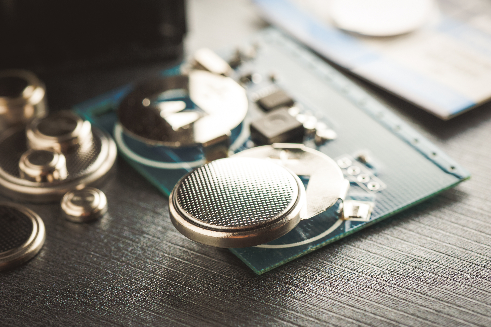
How to choose a CMOS battery?
Buying a new CMOS battery can be tricky because laptops use different connectors, voltage, polarity, wire length, and battery size.
Most laptops have a single-use CR2032 battery but on some occasions, smaller laptops use a rechargeable ML1220 battery. In addition to CR2032, some brands also use CR1220, CR1616, CR1620, CR1632, CR2016, CR2025, CR2450, and custom-made Ni-MH batteries. Sometimes battery type is not written on the battery shield, so the shield has to be carefully removed.
Connectors can also vary as some laptops have 2-pin and 3-pin of different shapes. Some 3-pin connectors use only two wires and have an unused pin. Wires are color-coded based on their polarity where red wire means positive and black or white wire means negative. It is important to pay attention to polarity to avoid damage to the motherboard.
Laptop motherboard design varies between each model and the CMOS battery slot is not always located near the connector. It is important to measure the length of the wires from the connector to the battery so the replacement battery can be located in the same slot as the original.
The typical battery voltage is 3V; however, some older custom Ni-MH batteries can go up to 7.2v. Generally, the original battery will have voltage and capacity written on it. The replacement battery has to have the same voltage to function correctly.
Motherboard battery removal and replacement
Before buying a new battery, remove your original battery and look for the part number. Buying a replacement with a matching part number guarantees a 100% fit. Most CMOS batteries are cross-compatible with different brands and some third-party manufacturers maintain a database of part numbers.
If your battery has no part number, then you can try to match it up visually with a replacement battery. You can find replacement pre-made batteries on Amazon and eBay, or through a specialized vendor like Rome Tech BIOS Batteries which can make a custom solution through their battery builder configurator. To use a configurator, you have to start by matching up the connector in step 1, polarity in step 2, cable length in step 3, and battery type in the last step.
Installation is very straightforward if a replacement battery is a 100% match. First, plug in the connector, then peel off the tape on the bottom and place it into the slot where the original battery was located. Your computer should boot up error-free and you will need to adjust the time and settings one last time.
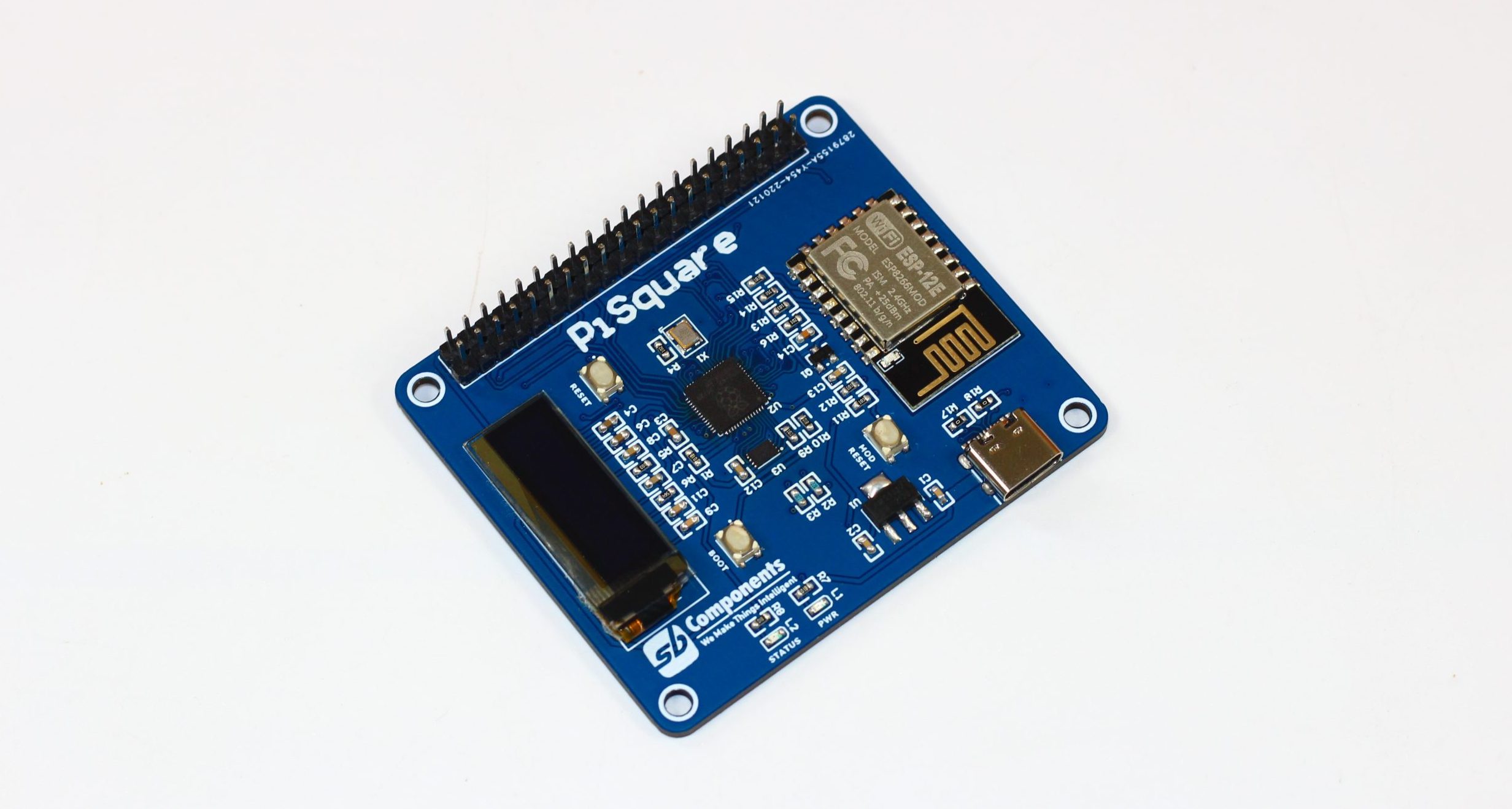
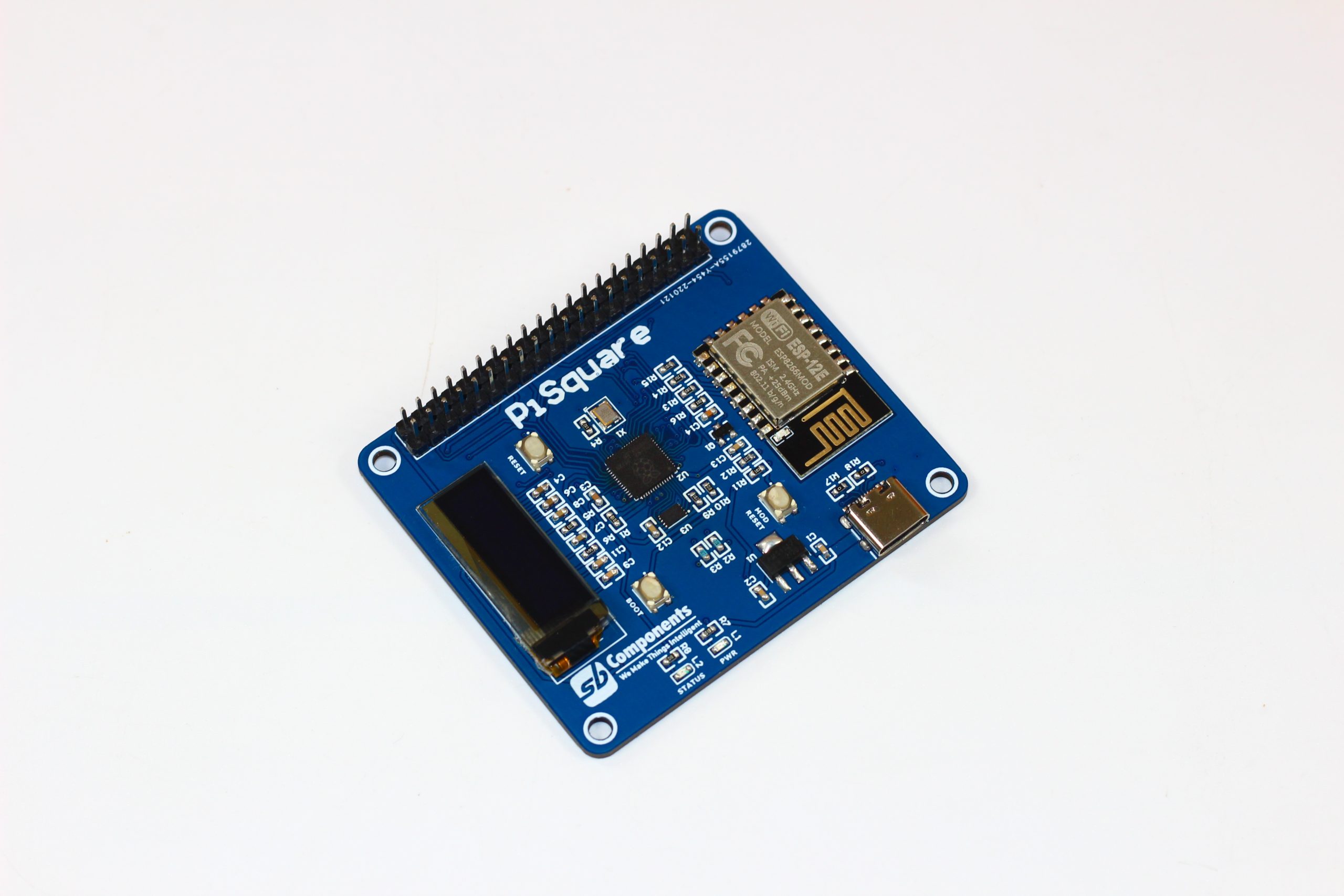
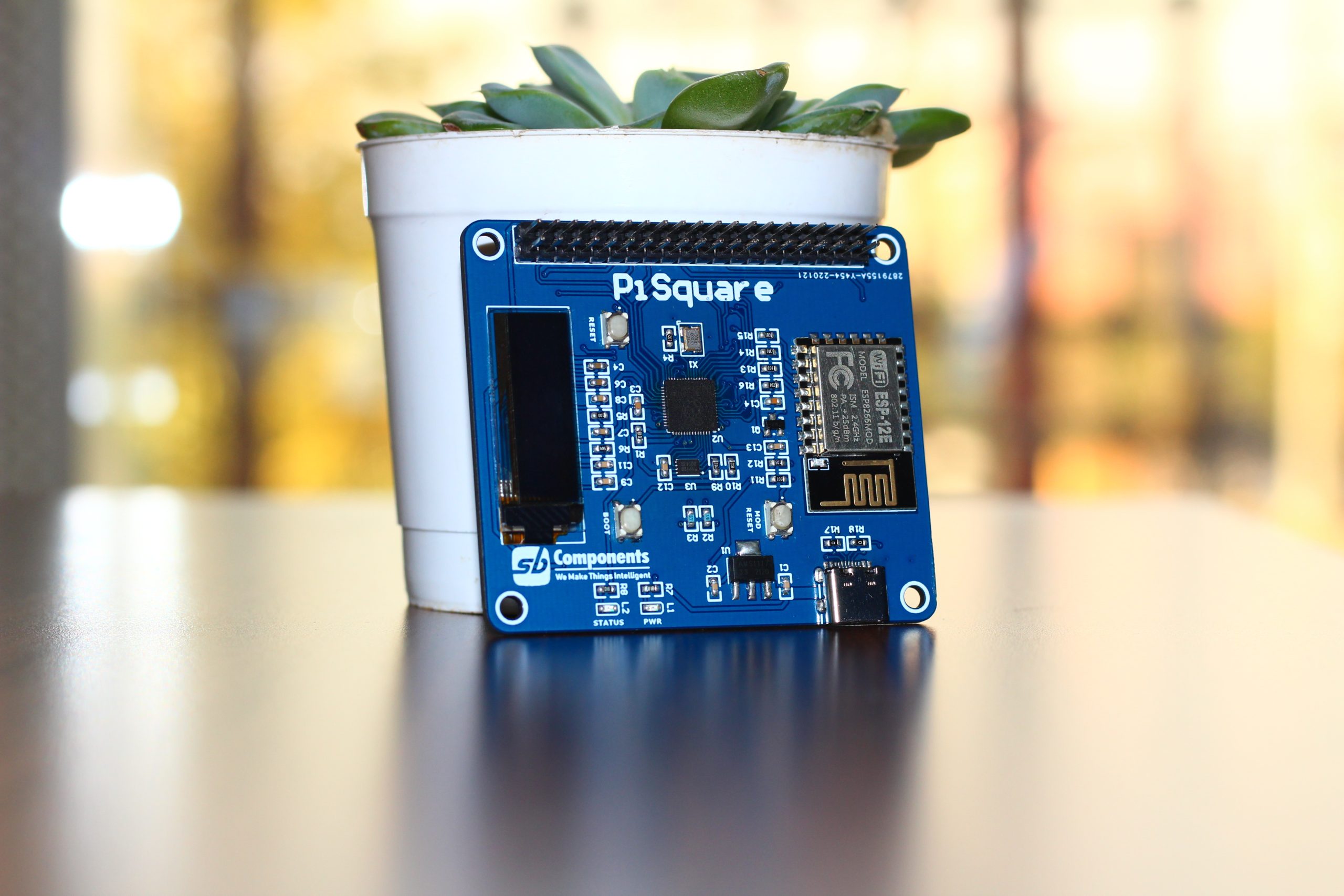
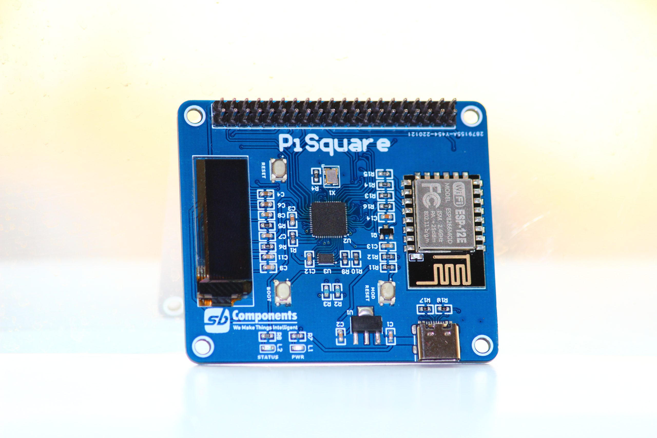
Onboard-RP2040 | USB-C Type Port | Multiple HAT Connectivity | ESP8266 | 0.91 OLED | 40-Pins GPIO Connectivity | 16 Mega-Byte Flash
There are several ways where you can find PiSquare very useful, as we were bound to use a single HAT on Raspberry Pi or max to max 5 Raspberry Pi HATs using PiStack, but you can’t connect the same HATs twice on it (Like more than two UART or SPI based Raspberry Pi HAT at the same time) PiSquare let you connect as many HATs you want to without stacking it on Raspberry Pi whether it is SPI, I2C or SPI HATs and you can operate all Raspberry Pi HATs wirelessly.
“PiSquare an RP2040 & ESP-12E based board, a smart way to use multiple Raspberry Pi HATs without stacking on Raspberry Pi. PiSquare uses Socket programming to communicate Multiple (“n” numbers of HATs) Raspberry Pi HATs wirelessly.”
How PiSquare Work?
With PiSquare You can create the server from Raspberry Pi and run as many HATs as you like as a client to run multiple Raspberry Pi HATs, You can also make the PiSquare a client and run it as a master for all the other PiSquare as much as you want, Run any HAT on single PiSquare and control it via your phone, Make two Way communication between the client and server from PiSquare.
PiSquare Highlights
Easily control all PiSquare Pins as Pins are Similar to Raspberry Pi
Connect & Run Multiple HATs as many you can
You can also use PiSquare as a Master/Server
Get Rid of Single SPI, UART, or I2C communication
Can Be Control from Smartphone
Easy Programming (PiSquare Use Socket Programming)
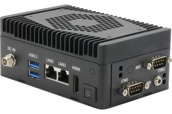
AAEON, an industry leader in embedded solutions, is delighted to announce the PICO-TGU4-SEMI, a new addition to its range of compact Pico-ITX boards. With an 11th Gen Intel® Core™ i7/i5/i3/Celeron Processor SoC, the PICO-TGU4-SEMI has extremely high CPU performance, and is the latest in AAEON’s impressive Single Board Computer range.
With the perfect balance of speed, power, and expansion capability, the PICO-TGU4-SEMI is the ideal embedded solution for deployment in AI edge technologies, and excellently demonstrates AAEON’s continued expertise in providing AI edge solutions.
Among many impressive features, the 11th Gen Intel® Core™ Processors allow users ample power to support AI applications in fields such as robotics, drone technology, and industry. This, combined with two expansion slots; one M.2 M Key 2280 slot, and one full-size mini card slot. These allow the user to provide additional support to the PICO-TGU4-SEMI, such as adding AI accelerators, additional storage, Wi-Fi, or Bluetooth capabilities.
In addition to this, the PICO-TGU4-SEMI offers rich I/O, with the option of up to 8 USB ports, two optional RS-232/422/485 serial ports, and a high definition audio interface.
The optional addition of a TPM chipset offers users an added layer of security, particularly where the PICO-TGU4-SEMI is deployed with drone technology, where the light weight of the board lends itself well to such dynamic applications.
The PICO-TGU4-SEMI’s high CPU performance is due to the 11th Gen Intel® Core™ i7/i5/i3/Celeron Processors on the compact PICO-ITX form factor, allowing for elite speed when running AI edge applications. Such speed makes the PICO-TGU4-SEMI perfect for AI Edge deployment in drones, robotics, or factory applications.
The wide range of applications that the PICO-TGU4-SEMI can be integrated with, along with its scalability, represents AAEON’s commitment to producing the highest quality embedded boards, to help its customers build more and more exciting AI edge applications.
A digital logic circuit can be represented by Boolean Algebraic expression. It is a simple and effective way to describe digital circuit behavior and switching action. It is known that Boolean Algebra uses a set of rules and laws to reduce the logic gates or Boolean expression whilst keeping the particular logical operation unaltered. The digital logic circuits are constructed using logic gates such as AND, OR, and NOT gates, and these logic gates constitute a “Full Set”. This means that every other logical function can be constructed using the members of a “Full Set”.
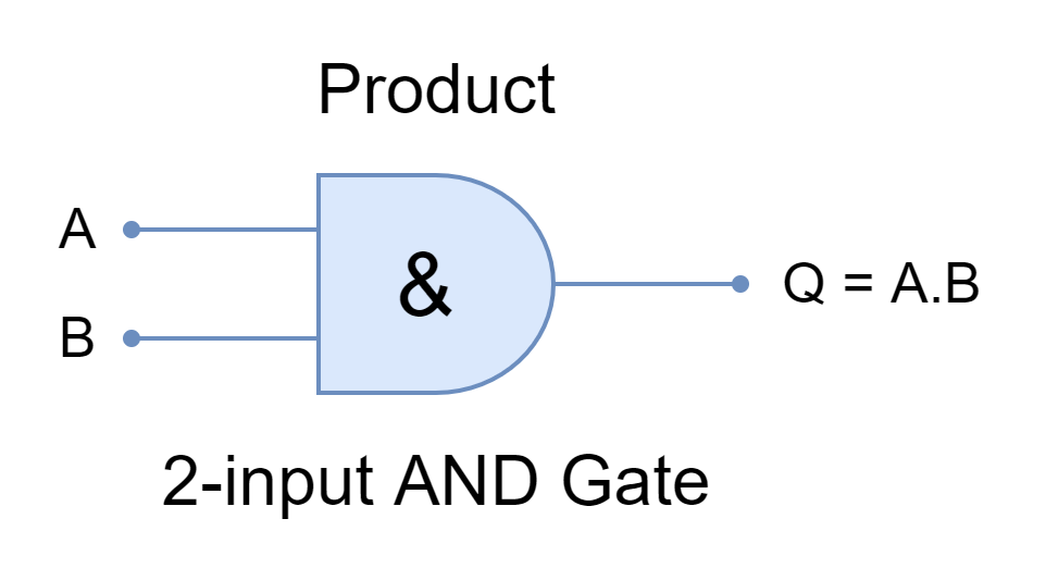
Similar to the mathematical operators, there are equivalent logical or Boolean operators. A product or multiplication in mathematics is denoted by “x” between operands and this multiplicative operator produces a product. For example, the multiplication of 4 by 5 is represented by “4 x 5” producing a product of “20”. In expression, it is represented by “4 x 5 = 20”. Similarly, in Boolean Algebra, the multiplication operation is performed by AND function or logic gates. The operands to be multiplied are inputs to the AND gate and this AND’ing produces a product. The Boolean multiplication is represented by a dot (.) between the inputs or operands. In expression, it is represented by “Q = A.B” where A & B are operands and Q is the logical product.
Figure 1: The AND Gate with a Boolean expression
The digital logic circuits use a Boolean data type having only two distinct states i.e. “0” or “1”. The states of “0” and “1” are also represented by “LOW” and “HIGH”, respectively. Whereas, in switching theory, “0” and “1” are referred to as “OFF” and “ON”, respectively.
The Product (AND) Term
In Boolean Algebra, product (multiplications) means resultant/ output of AND operation. The logical inputs are AND’ed together to yield a logical output. The product includes each possible instance of variables having a true or complementary form. These instances occur only once and are called “minterms”. A minterm is a product term in a Boolean function in which every element is present is either in normal or in complemented form. For example, F(A, B) function has possible minterms of AB, A’B, AB’, and A’B’.
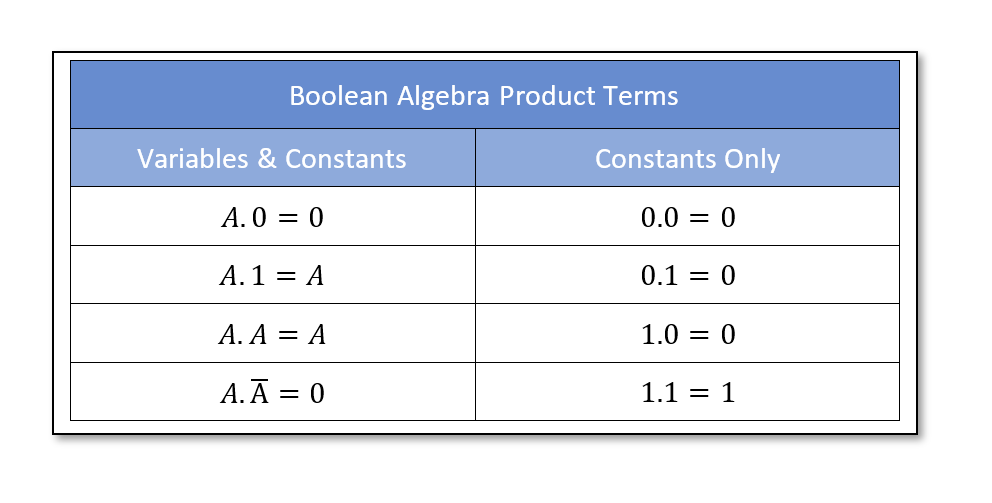
These minterms can have two or more input variables or constants with two possible states of “0” and “1”. The following table gives possible input states with all possible combinations.
From the above table, the product of two variables can be simplified into a single constant using the following Boolean laws wherein “A” represents a variable input and “0” & “1” as constant inputs.
Annulment Law
AND operation of a term with 0 is always equal to 0 i.e. A.0 = 0
Complement Law
AND operation of a term with its complement is always equal to 0 i.e. A.A’ = 0
Commutative Law
The AND operation is independent of the order of terms i.e. A.1 = 1.A
Idempotent Law
The AND operation of a term with itself is always equal to term i.e. A.A = A
Identity Law
The AND operation of a term with 1 is always equal to term i.e. A.1 = A
The Sum (OR) Term
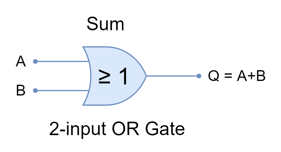
As described earlier in this article the AND function is termed as the product term because it produces the product. On the other hand, the OR function can be designated as a Sum term as it produces the sum of inputs/ variables. The OR function is similar to the sum operation of conventional mathematics and is also denoted by a plus (+) sign between operands. In expression form, it is expressed as “Q = A + B” where A & B are input variables and Q is the sum term.
Figure 2: The OR Gate with a Boolean expression
Sum of Products
In a nutshell, the AND function gives the logical product of Boolean multiplication. Likewise, the OR function gives the logical sum of Boolean addition. However, most digital circuits consist of multiple logic gates including AND, OR, and NOT gates which constitute combinational logic circuits. The combinational logic circuits are widely expressed as Sum-of-Products or Product-of-Sums as they include both AND, and OR functions, mainly.
The Sum-of-Products (SOP) expresses the combinational logic as two or more products are summed together. In logical terms, the outputs of two or more AND functions (constituting products) are connected to OR function (summed together) to give Sum-of-products. It is an AND-OR logic operation having two or more AND terms and only one OR term. A few examples of Sum-of-Product (SOP) are given below:
and,
The Boolean expressions are not always in standard sum-of-product (SOP). The non-standard forms can be converted to the sum-of-product form. In the following example, a non-standard Boolean expression is converted to sum-of-product (SOP).
Constructing a Truth Table from Sum-of-Product (SOP) Expression
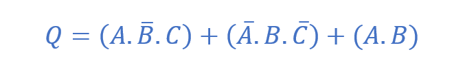
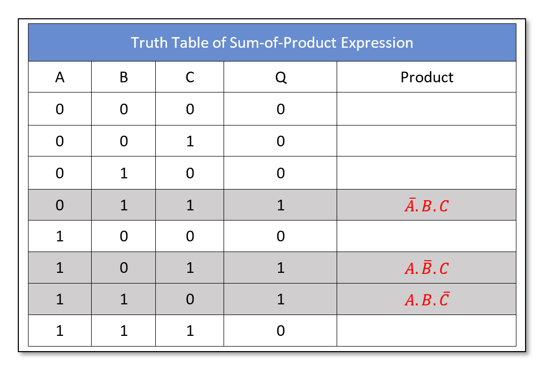
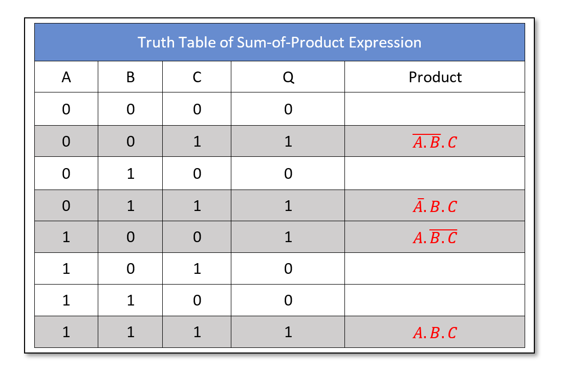
A truth table can be constructed from a sum-of-product expression and, conversely, a sum-of-product expression from a truth table. The terms in the sum-of-product expressions produce a logic “1” for that specific input state of terms. For example, the A.B.C term will produce a “1” state when A=1, B=1, & C=1. Similarly, A.B.C’ is “1” when A=1, B=1, & C=0. In a similar manner, the truth table is constructed for all the terms for that specific inputs’ state and their output is set to “1”. The output of all other states is set to “0”. Consider the following Boolean expression:
The following truth table is drawn for all of the possible states of A, B, and C. The output of the above expression is set to “1” for all the terms of sum-of-products expression at their specific input states.
It is obvious from the above table that product terms are set to “1” for that specific state of inputs and the rest of the output states are set to “0”. When any of the terms is “1” then OR (sum) function sets the output to “1”.
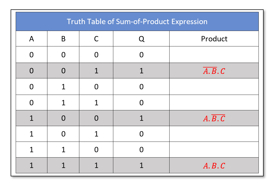
Likewise, a Boolean sum-of-product (SOP) expression can be constructed from a given truth table. Consider the following truth tables.
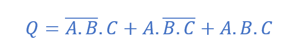
From the above truth table, the following sum-of-products expression is derived.
Sum-of-Product Example
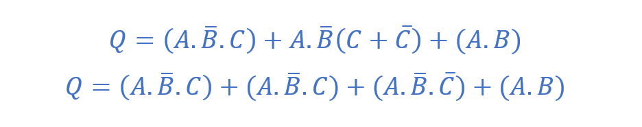
Consider the following given Boolean expression:
The expression is in non-standard form of the sum-of-product and as such converted into SOP form:
The following truth table is constructed from the above sum-of-product expression.
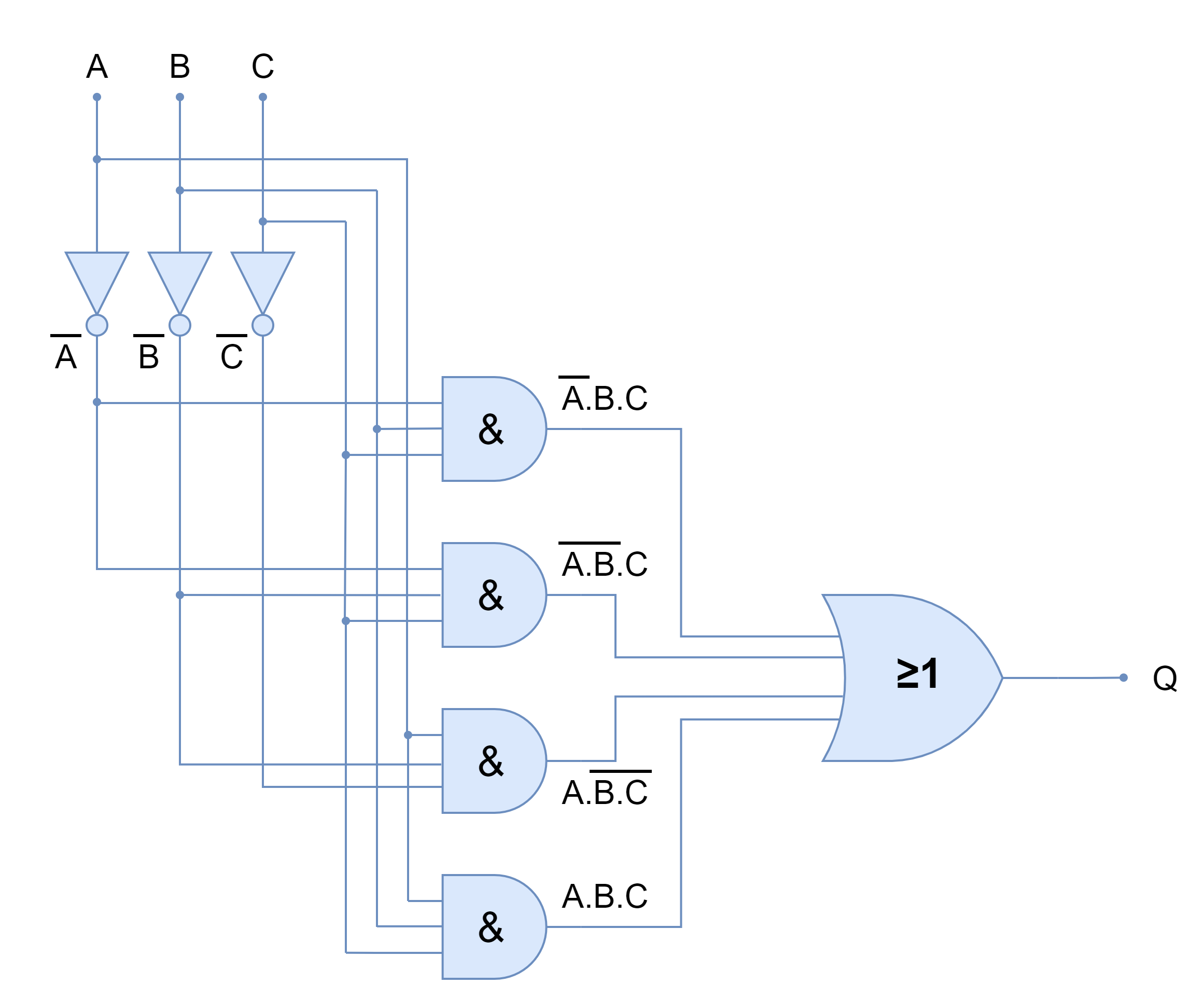
From the given sum-of-products expression following logic diagram is created.
Figure 3: The Logic Gate diagram of SOP expression
Following the above example, any non-standard expression can be converted into a sum-of-product expression and a truth table from it.
Conclusion
A Sum-of-Product expression is a logical equivalent of two or more AND functions that are summed together. It is AND-OR logic which has more than two AND logics and only one OR logic.
In Boolean, the logical AND function performs multiplication and produces a product. Whereas, the logical OR function performs addition and produces a sum. In this way, the AND-OR logic is given the name of sum-of-product.
A minterm is a product term in a Boolean function in which every element is present is either in normal or in complemented form.
The combinational digital circuits consist of AND, OR, and NOT logic gates and are commonly described in sum-of-product (SOP).
A truth table can be constructed easily from the given sum-of-products expression and vice versa.
In the truth table, the outputs are set to “1” for terms included in the sum-of-products expression at that specific input state only, and the rest of the outputs are set to “0”.
New innovation provides weight savings for applications where size, weight and power (SWaP) are key
TeledyneLabtech announces a major new capability allowing the embedding of layers of synthetic graphite within RF and microwave printed circuit boards (PCBs). Heat management is a significant concern in many aerospace, defense and space applications where size, weight and power (SWaP) are key attributes. Gallium nitride (GaN) solid-state power amplifiers (SSPAs) are examples of increasingly common devices that benefit from careful heat management. This new technique allows efficient conduction of heat away from such devices, saving system weight and increasing their lifetime.
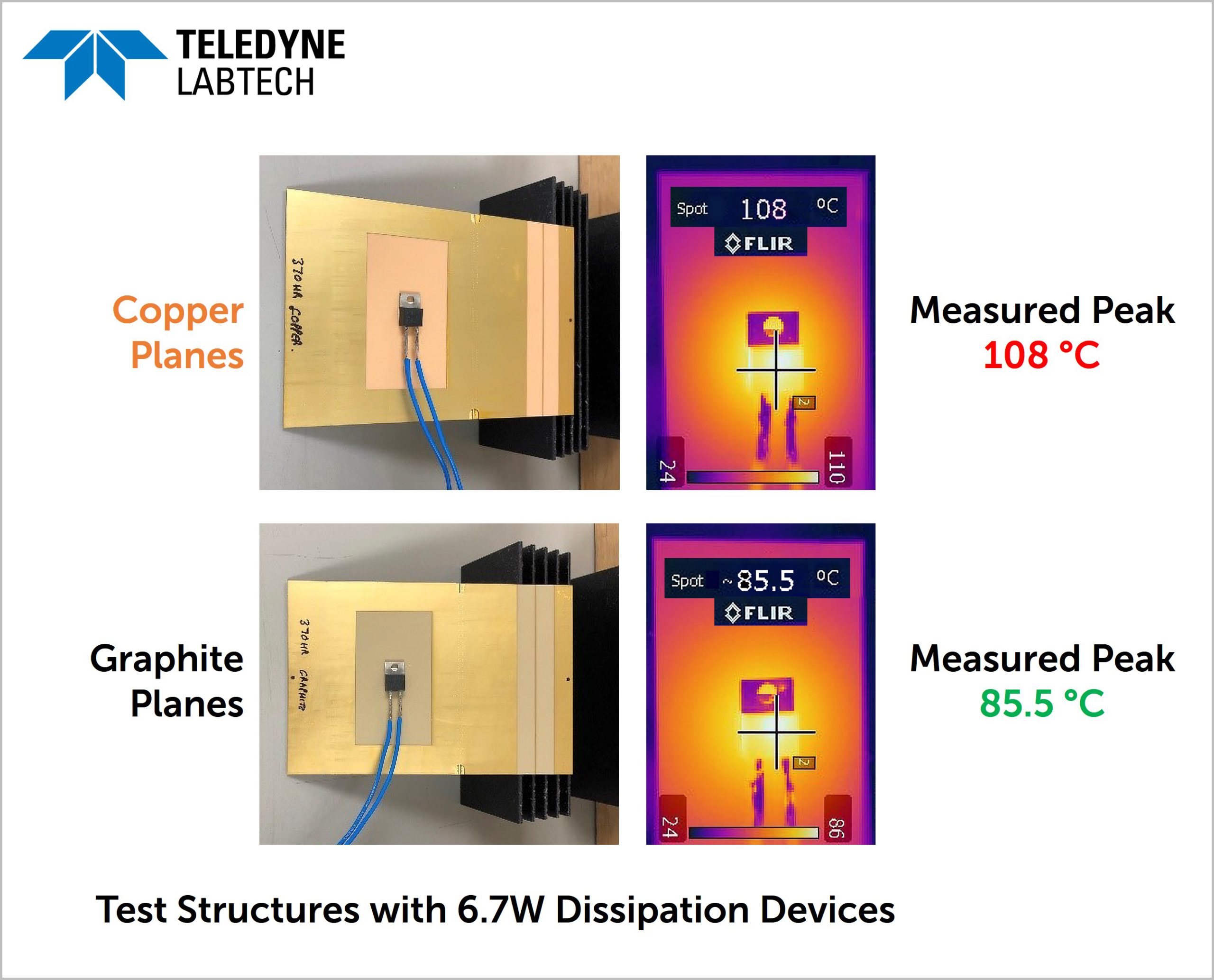
Managing waste heat is a significant problem in today’s electronic systems, impacting reliability and requiring added expense and weight to control effectively. In the latest consumer mobile phones, it is common to employ sheets of self-adhesive synthetic graphite on top of critical semiconductor devices in order to conduct away waste heat from small areas. Aerospace, defense and space applications require more precision, repeatability and area of coverage. To address this, Teledyne Labtech has developed a method of embedding thin layers of synthetic graphite inside the structure of the host PCB reliably, saving size and weight, while increasing the lifetime of active devices (MTBF) by permitting operation at cooler steady state.
“Synthetic graphite is 4 times lighter than copper, and transfers heat 4 times better in the X-Y plane,” said John Priday, CTO of Teledyne Labtech. “Replacing PCB ground plane layers with it in critical applications such as T/R modules can cause devices to run up to 20°C cooler in our testing.”
Labtech has demonstrated that thermal copper layers can be replaced with the new graphite technique while remaining reliable and experiencing minimal impact on the passage of microwave signals on grounding layers.
Teledyne Labtech will be available to discuss this new innovation at Booth 1324 of the Satellite Show in Washington, DC, March 22nd-24th.