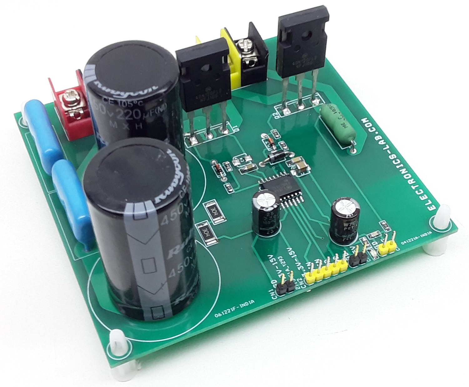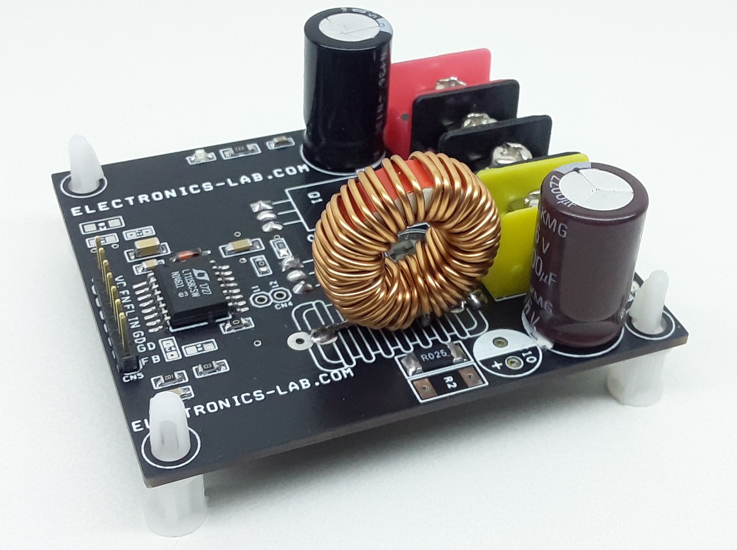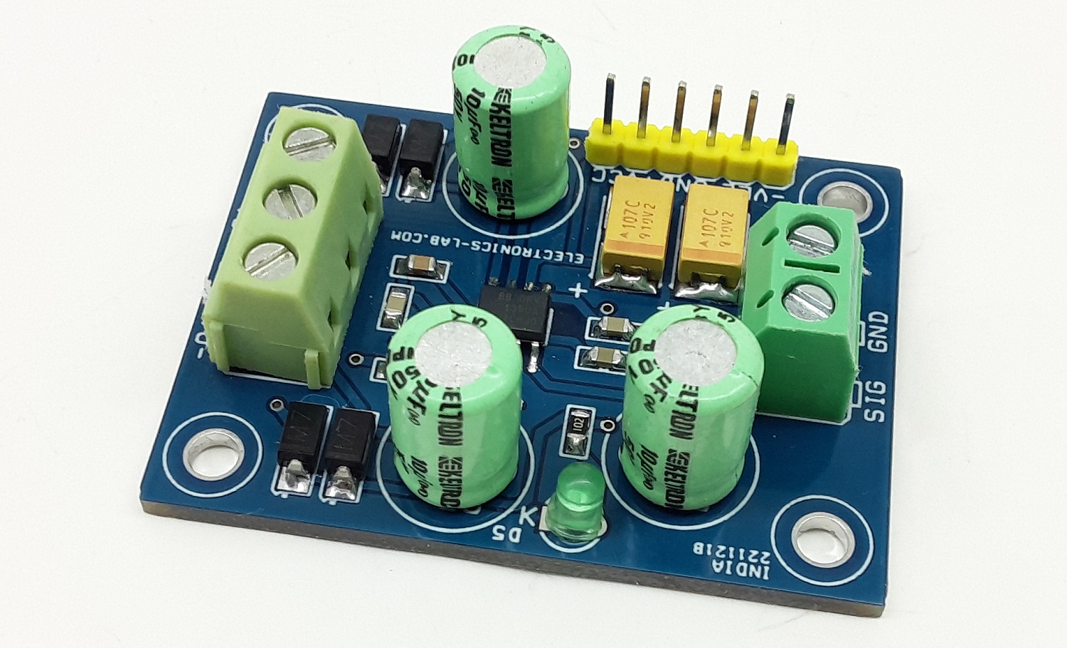
The project presented here is a differential output amplifier that converts a single-ended audio signal input to a balanced output pair. This balanced audio project consists of high-performance OPAMPS with on-chip precision resistors. They are fully specified for high-performance audio applications and have excellent AC specifications, including low distortion (0.0005% at 1 kHz) and high slew rate (15 V/µs). The board is based on DRV135 from Texas Instruments.
The on-chip resistors are laser-trimmed for accurate gain and optimum output common-mode rejection. Wide output voltage swing and high output drive capability allow use in a wide variety of demanding applications. They easily drive the large capacitive loads associated with long audio cables.
This project is used in combination with the Audio Line Receiver using INA134 as the receiver. Together they offer a complete solution for transmitting analog audio signals without degradation over a long distance.
Features
- Single-Ended Audio Input and Balanced Output
- Low Distortion: 0.0005% at f = 1 kHz
- Wide Output Swing: 17Vrms into 600 Ω
- High Capacitive Load Drive
- High Slew Rate: 15 V/µs
- Wide Supply Range: ±4.5 V to ±18 V @ 15mA without Load
- Low Quiescent Current: ±5.2 mA
- Companion to Audio Differential Line Receivers: INA134
- Improved Replacement for SSM2142
- PCB Dimensions 48.26 x 36.20 mm
Applications
- Audio Differential Line Drivers
- Audio Mix Consoles
- Distribution Amplifier
- Digital Effects Processors
- Hi-Fi Equipment’s
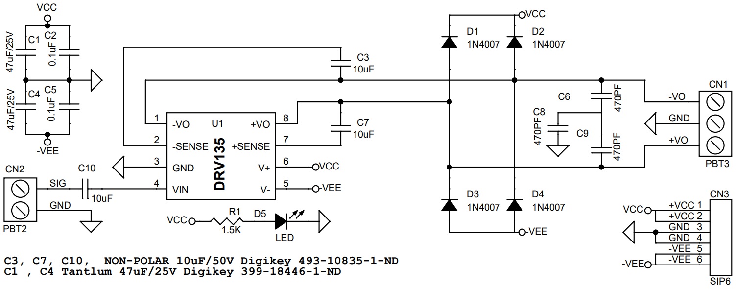
Schematic
Parts List
| NO. | QNTY. | REF. | DESC. | MANUFACTURING | SUPPLIER | PART NO |
|---|---|---|---|---|---|---|
| 1 | 1 | CN1 | 3 PIN SCREW TERMINAL PITCH 5.08MM | PHOENIX | DIGIKEY | 277-1248-ND |
| 2 | 1 | CN2 | 3 PIN SCREW TERMINAL PITCH 5.08MM | PHOENIX | DIGIKEY | 277-1248-ND |
| 3 | 1 | CN3 | 6 PIN MALE HEADER PITCH 2.54MM | WURTH | DIGIKEY | 732-5319-ND |
| 4 | 2 | C1,C4 | 47uF/25V | KEMET | DIGIKEY | 399-18446-1-ND |
| 5 | 2 | C2,C5 | 0.1uF SMD SIZE 0805 | MURATA/YAGEO | DIGIKEY | |
| 6 | 3 | C3,C7,C10 | 10uF/50V NON-POLAR | NICHICON | DIGIKEY | 493-10835-1-ND |
| 7 | 3 | C6,C8,C9 | 470PF/50V SMD SIZE 0805 | MURATA/YAGEO | DIGIKEY | |
| 8 | 4 | D1,D2,D3,D4 | 1N4007 SMD | SMC DIODE SOLUTION | DIGIKEY | 1655-1N4007FLCT-ND |
| 9 | 1 | D5 | LED SMD SIZE 0805 | LITE ON INC | DIGIKEY | 160-1427-1-ND |
| 10 | 1 | R1 | 1.5K 5% SMD SIZE 0805 | MURATA/YAGEO | DIGIKEY | |
| 11 | 1 | U1 | DRV135 SOIC8 | TI | DIGIKEY | DRV135UA-ND |
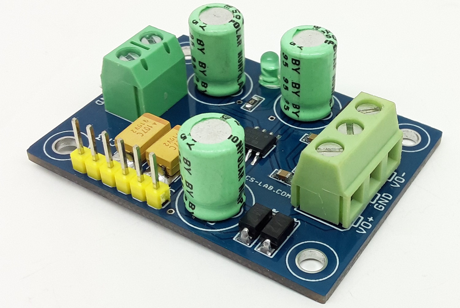
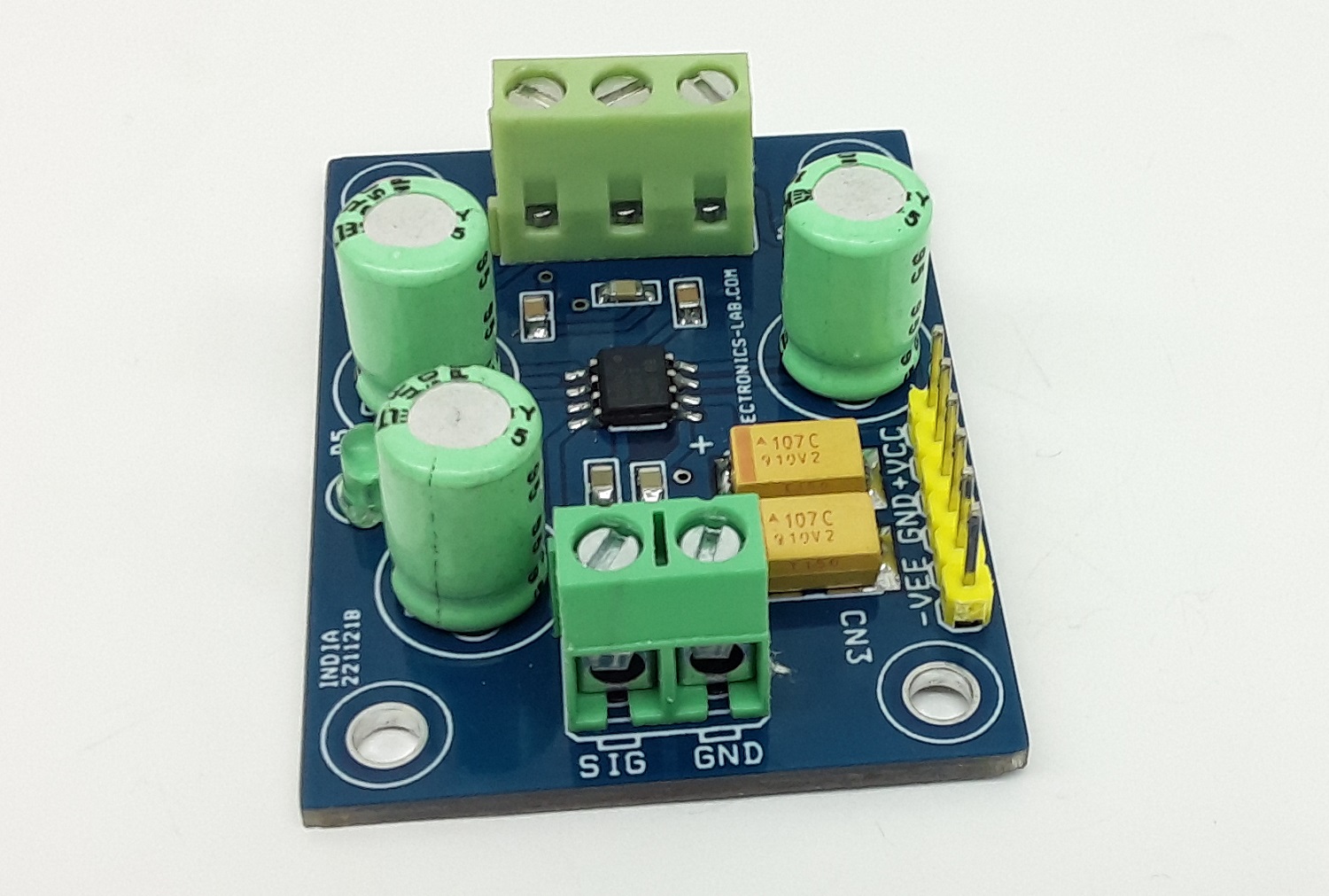
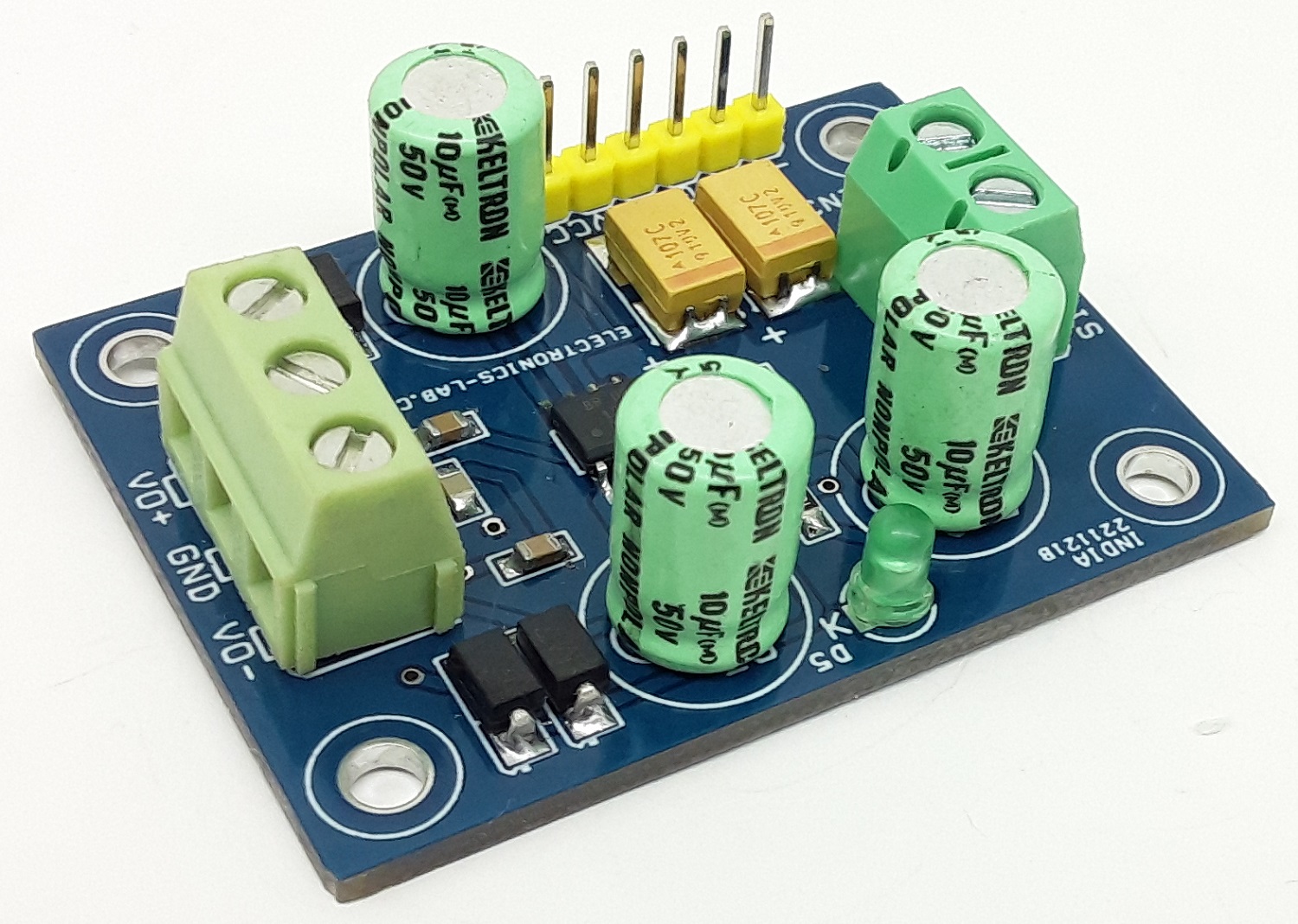
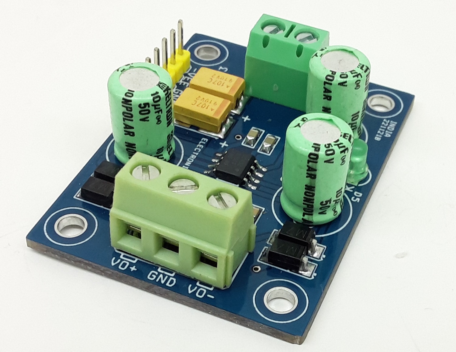
Connections
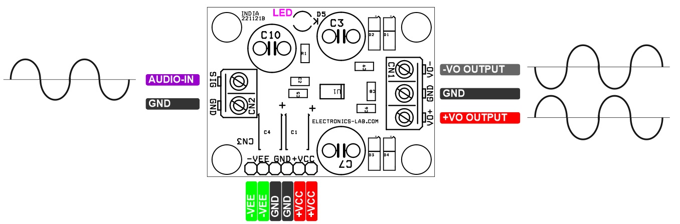
Application Diagram
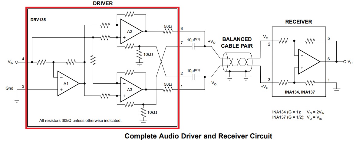
Transmitter/Receiver Diagram
Gerber View
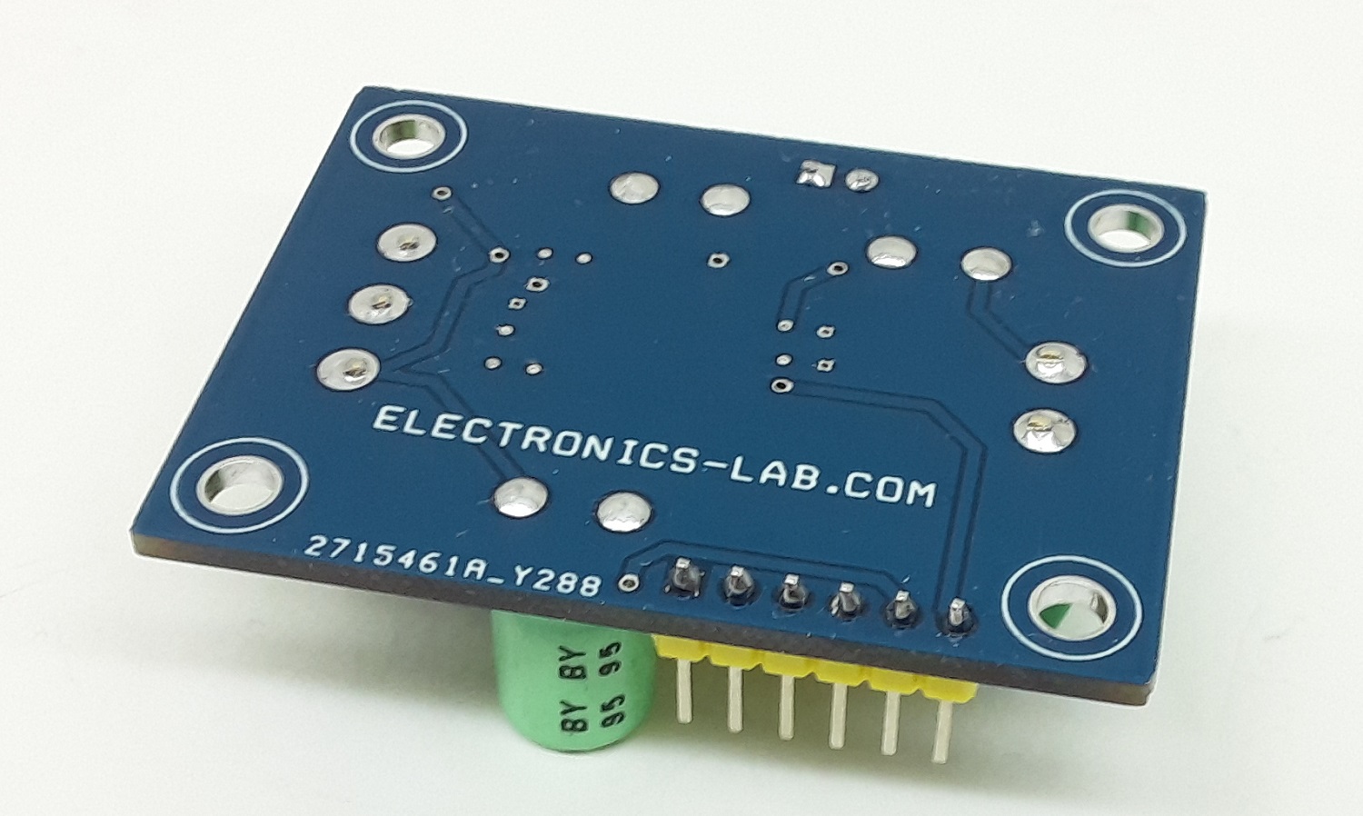
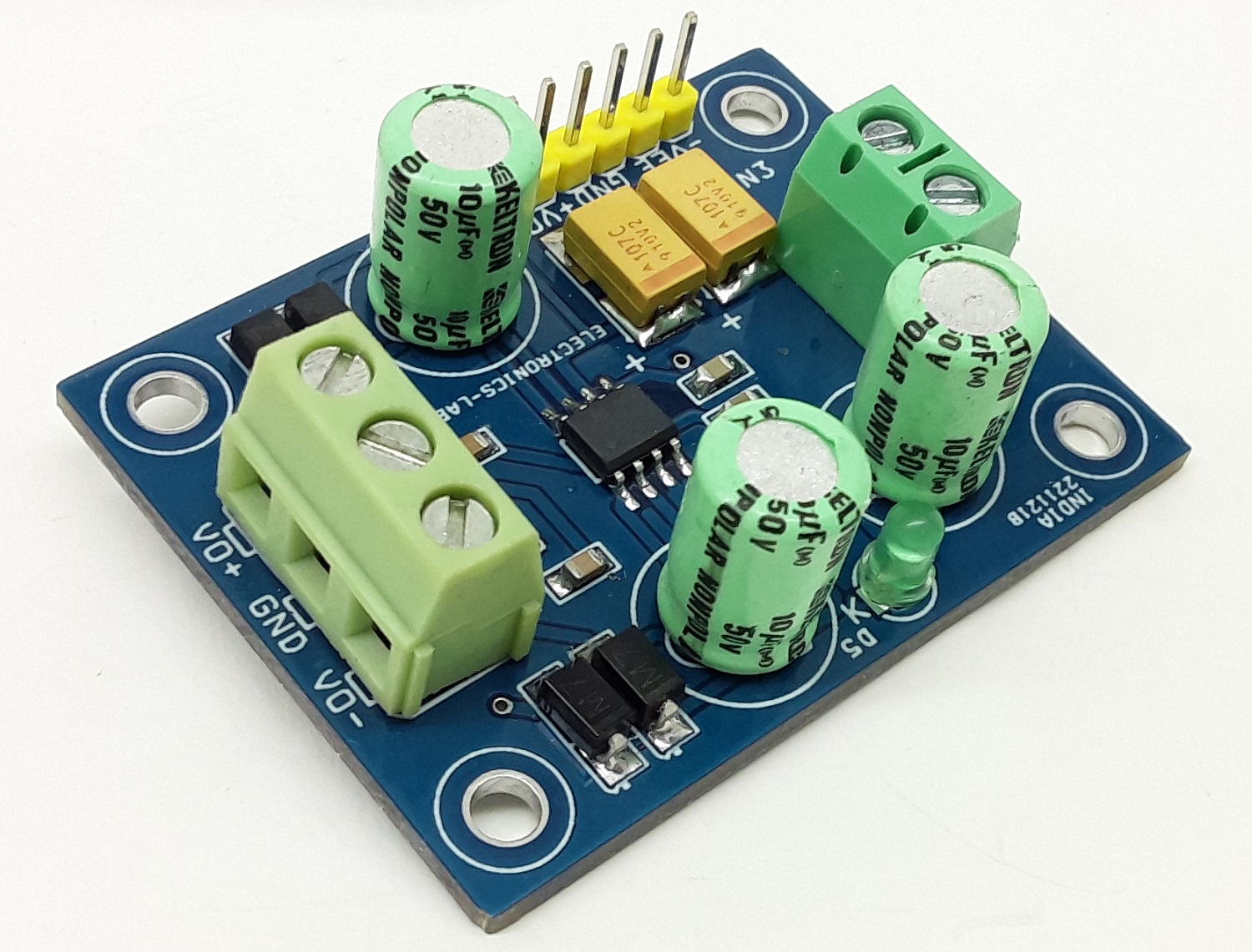
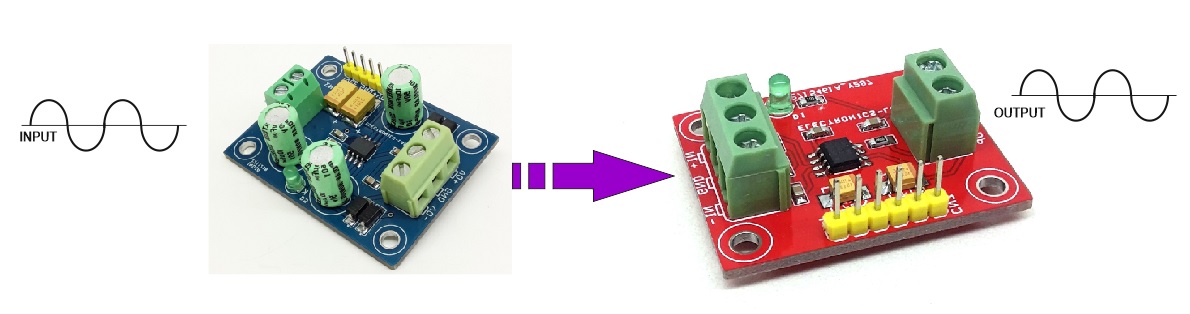
Photos