New R&S LCX strengthens Rohde & Schwarz portfolio for high performance impedance measurements

With a completely new family of high performance LCR meters, the frequency range of impedance measurements provided by Rohde & Schwarz test equipment is dramatically extended to cover AC components operating from 4 Hz to 10 MHz, supporting all practical applications.

The R&S LCX family of LCR meters serves all established impedance measurements plus specialized measurements for selected component types and provides both, the high accuracy required in R&D, and the high speed needed in production test and quality assurance.

Rohde & Schwarz launches its new LCR meter family of high-performance general-purpose impedance testers covering a wide range of applications. With its supported frequency range from 4 Hz to 10 MHz, the R&S LCX is suitable not only for the vast majority of devices operating at conventional 50 or 60 Hz domestic power frequencies or 400 Hz for aircraft but also for everything from low-frequency seismic sensors to high power communication circuits operating at several Megahertz.

For engineers selecting suitable capacitors, inductances, resistors, and analog filters to match the device application, the R&S LCX models provide high precision impedance values with market-leading accuracy. Equally, higher speed measurements at production-use accuracy for quality control and monitoring are also supported. All the essential software and hardware required for production environments is available, including remote control and result logging, as well as rack mounting for the instrument, and a full range of test fixtures for handling components.

The auto-balancing bridge technology used by the R&S LCX supports conventional impedance measurements by measuring the AC voltage and current for the device under test, including the phase shift. This is then used to calculate complex impedance at any given operational point. As a general purpose LCR meter, the R&S LCX covers many applications, such as the measurement of equivalent series resistance (ESR) and equivalent series inductance (ESL) of electrolytic capacitors and DC-link capacitors. Furthermore, users can test transformers and measure DC resistance in addition to the full range of impedance measurements. To investigate components with impedance values varying at different frequencies and levels, option R&S LCX-K106 supports dynamic impedance measurements with the frequency, voltage or current as the swept parameter.

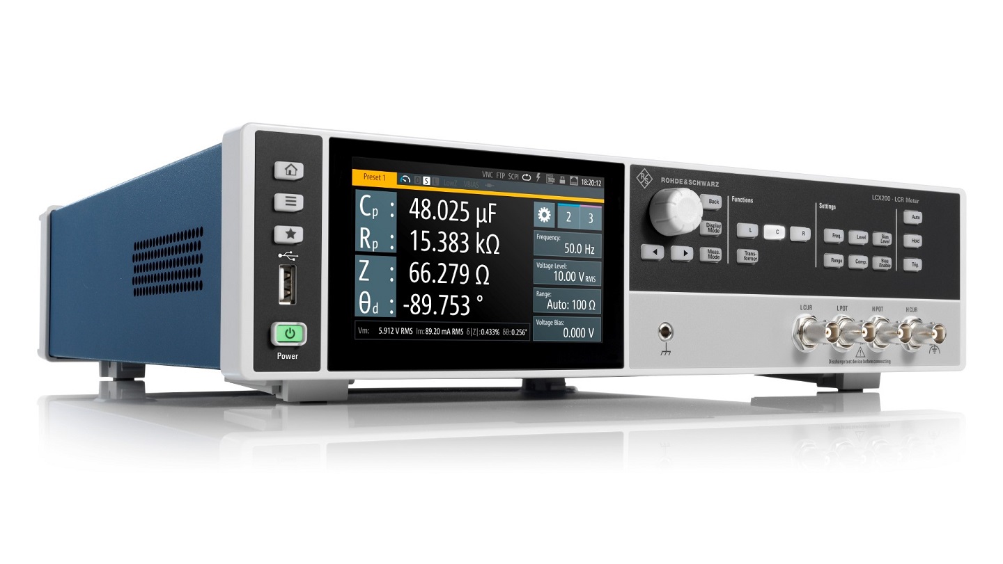
The R&S LCX family is launched with two models; the R&S LCX100 covers a frequency range from 4 Hz to 300 kHz, the R&S LCX200 a basic frequency range from 4 Hz to 500 kHz with options to cover all frequencies up to 10 MHz. Both models feature a large capacitive touchscreen and virtual keyboard to support tap-and-test for all main measurements. Alternatively, voltage, current, and frequency values can be set using the rotary knob. Less frequently used functions are menu-operated. Settings, results, and statistics can be displayed on the screen or output for automated post-processing. Up to four measurements can be selected and plotted versus time, with minimum and maximum values included in the display for at-a-glance pass/fail analysis.

For investigating impedance in a wider range of materials, the MFIA impedance analyzer from Zurich Instruments AG, a subsidiary of Rohde & Schwarz, complements the R&S LCX perfectly. With the MFIA researchers can characterize semi-conductors or undertake material research into materials including dielectrics, piezoelectrics, ceramics and composites, as well as tissue impedance analysis, cell growth, food research, microfluidics, and wearable sensors.

The R&S LCX family of LCR meters is part of the R&S Essentials portfolio and is now available from Rohde & Schwarz and selected distribution partners. For further information on the R&S LCX visit https://www.rohde-schwarz.com/product/lcx. For more information the LCR meter portfolio from Rohde & Schwarz, including the MFIA from Zurich Instruments AG, visit https://www.rohde-schwarz.com/lcr-meters.

ams OSRAM AS7343 14-Channel Multi-Spectral Sensors

ams OSRAM AS7343 14-Channel Multi-Spectral Sensors integrate high-precision optical filters onto standard CMOS silicon via deposited interference filter technology. These AS7343 sensors feature a spectral response that is defined by individual channels covering approx. 380nm to 1000nm with 11 channels centered in the visible spectrum (VIS), plus 1 near-infrared (NIR), and a clear channel. The AS7343 also includes an integrated flicker detection channel that can automatically flag ambient light flicker at 50/60Hz, as well as buffer data for externally calculating other flicker frequencies.

The sensors are optimized for transmissive, reflective, and emissive measurements including fluid or reagent analysis, color matching, spectral identification in the visible range, and lateral flow test applications. The AS7343 Multi-Spectral Sensors from ams OSRAM are available in an ultra-low profile package with dimensions of 3.1mm x 2mm x 1mm.

Features

  • 14-channels between 380nm and 1000nm
  • Reflective, transmissive, and emissive applications
  • Enables ultra-low light operation
  • Enables operation behind dark glass or additional external filters
  • 18V VDD operation
  • Configurable sleep mode
  • Interrupt-driven device
  • On-chip interference filter technology
  • Integrated LED driver and 6 integrated ADCs
  • 3.1mm x 2mm x 1mm package outline

Block Diagram

more information: https://ams.com/as7343

ams OSRAM AS5070 On-Axis Magnetic Angular Position Sensors

ams OSRAM AS5070 On-Axis Magnetic Angular Position Sensors are high-resolution, Hall-based rotary magnetic position sensors that utilize CMOS technology and provide precise absolute angle measurements. The AS5070 is available with an analog output interface (AS5070A) or a digital output interface (AS5070B). The AS5070B can be programmed as a PWM or a SENT-compliant output interface. These sensors measure the orthogonal component of the flux density (Bz) over a full turn rotation and compensate for external stray magnetic fields with a robust architecture based on a 14-bit sensor array and analog front-end (AFE). A sub-range can be programmed to achieve ideal application resolution.

A simple two-pole magnet rotating over the center of the package is required to measure the angle. The magnet may be placed above or below the device. The absolute angle measurement provides an instant indication of the magnet’s angular position. The AS5070 operates at a supply voltage of 5V, and the supply and output pins are protected against overvoltage up to +20V. In addition, the supply pins are protected against reverse polarity up to -20V.

Features

  • Hall-based rotary magnetic position sensor using CMOS technology
  • Resolvessmall angular excursion with high accuracy
  • 12-bit resolution at 90° minimum arc
  • Low output noise, low inherent INL
  • Magnetic stray field immunity
  • Programmable output
  • CORDIC block (Coordinate-Rotation Digital Computer)
  • High durability and low system costs
  • Embedded linearization algorithm
  • 3x output interfaces
    • Analog ratiometric (AS5070A)
    • Digital PWM (AS5070B)
    • SENT (AS5070B)

Specifications

  • Operating
    • 4.5V to 5.5V supply voltage range
    • 3.3V to 3.6V regulated voltage range
    • Supply current range
      • 4mA to 12mA for the AS5070A
      • 4mA to 10mA for the AS5070B
    • 2.5mA to 10mA start-up supply current at 2.25V
    • 10ms start-up time
  • Electrical
    • 14-bit core resolution
    • 12-bit analog (AS5070A) and digital (AS5070B) resolutions
    • ±0.5° to ±0.9° integral non-linearity (optimum) range
    • ±1.4° integral non-linearity
    • 125µs typical sampling time
  • Magnet
    • Orthogonal magnet field strength
      • 30mT to 70mT range
      • 10mT to 90mT in extended mode
    • 0.5mm typical displacement radius
  • Power management, supply monitor, and timing
    • Undervoltage thresholds
      • 3.5VDD to 4.5VDD upper range
      • 3.0VDD to 4.0VDD lower range
    • 300mV to 900mV undervoltage hysteresis, 500mV typical
    • 10µs to 250µs undervoltage detection/recovery time range, 50µs typical
    • Overvoltage threshold
      • 6.0V to 7.0V upper range
      • 5.5V to 6.5V lower range
    • 300V to 900V overvoltage hysteresis range, 500V typical
    • 500µs to 2000µs overvoltage detection/recovery time range
    • 12ms maximum WatchDog error detection time

Block Diagram

more information: https://ams.com/en/as5070

SPI Programmable-Gain Amplifier with Input VOS Trim and Output OPAMP

The project presented here is an SPI programable Gain Amplifier using MAX9939. The MAX9939 is a general-purpose, differential-input programmable-gain amplifier (PGA) that is ideal for conditioning a variety of wide dynamic range signals such as those found in motor current-sense, medical instrumentation, and sonar data acquisition applications. It features SPI-programmable differential gains from 0.2V/V to 157V/V, input offset-voltage compensation, and an output amplifier that can be configured either as a high-order active filter or to provide a differential output.

SPI Programmable-Gain Amplifier with Input VOS Trim and Output OPAMP – [Link]

3-Phase Brushless DC Sinusoidal Sensorless Fan Motor Driver

Driving a low current 3 phase brushless Sensorless DC motor is very easy with this project. This Full-wave BLDC driver project is capable to drive low current brushless fan motor without a hall sensor. 180° sinusoidal drive, high torque output, and silent drive are a few key features of the project. Due to their adaptive features and wide power-supply range capabilities (3 to 12V) they are intended to cover a wide range of motor characteristics while requiring no external tuning from the user. Speed control can be achieved through either power supply modulation or pulse-width-modulation (using the PWM digital input pin5 of CN1). Due to the compact packaging and minimum bill-of-material (power transistors incorporated, no Hall sensor, no external tuning), the project is best suited for low-cost fan applications requiring high efficiency and low acoustic noise, such as CPU cooling fans. The frequency generator output is also included, enabling precision speed control in closed-loop applications. Motor over-current limitation, short-circuit protection, and thermal shutdown protection is also included. Connect 3 Phase Motor to CN2, Apply Motor Supply to GND and VCC of CN1, Apply PWM signal to PIN 5 of CN1. D1 Power LED.

3-Phase Brushless DC Sinusoidal Sensorless Fan Motor Driver – [Link]

ELSYS is launching ERS Eco, a battery-free sensor line powered by Epishine’s indoor solar cells.

Industry leading LoRaWAN sensor provider ELSYS is launching their first battery-free products using Epishine’s indoor light energy harvesting solution. The environmentally friendly sensor line is launching two sensor types called ERS Eco and ERS Eco CO2. They are entirely powered by Epishine’s indoor solar cells and are made from biodegradable materials.

“We are incredibly excited to release a new product line powered by indoor light and made of more durable materials. Combining a great solar cell with new technology and sustainable materials is completely in line with how we at ELSYS want our product development to be. We are proud to present a new product that will simplify installation and maintenance while reducing the CO2 footprint.” says Peter Björk, CEO at ELSYS.

The ERS ECO series enables customers to have complete control over their air quality and indoor environment. This in itself saves money and reduces its CO2 footprint, and its battery-free operation reduces the CO2 footprint even further.

ELSYS’ vision of making an environmentally friendly sensor, demanded battery-free operation, and a more sustainable enclosure design. The solution was cooperation between ELSYS and Epishine which resulted in a sensor that is powered solely by indoor solar cells as well as an enclosure made from biodegradable materials.

”ELSYS has taken sustainability to a new level within IoT and building automation sensors with the new ERS Eco sensor line. We are proud to be their partner, supplying our light energy harvesting modules. Epishine’s organic solar cells are perfectly optimized for the ERS Eco sensors with their market-leading performance in indoor light conditions.” says Jonas Palmér, Sales and Business Development at Epishine.

Sensors powered with Epishine’s indoor light energy harvesting modules do not only function uninterrupted when ambient light is available but also function continuously for up to seven days in the dark. This results in a solution with very low or no maintenance and with no need to ever change batteries again.

“This combination of energy harvesting from indoor light, battery-free operation, and a biodegradable enclosure is an IoT industry first. I believe that we at ELSYS, with ongoing support from Epishine, have developed a truly unique and ground-breaking product.” says David Skånehult, Hardware Engineer at ELSYS.

more information: www.epishine.com & www.elsys.se

X-Sense XP01-W Smoke and Carbon Monoxide Alarm Detector with Up To 10-Year Battery

Introduction

Almost all North American houses come with fire and smoke detector alarms, however, with poor maintenance, this product can defy the purpose. Here comes the combination of smoke and carbon monoxide detectors inside a compact consumer product, ready to be deployed in the home environment becoming an essential part of our life. The production of such alarm detectors has been on the rise from various manufacturers competing with almost the same functionalities but with minor tweaks and upgrades. Today, we will be reviewing the X-Sense XP01-W smoke and CO alarm detector with a large silence button that is currently available on Amazon for sale at $107.99 (3-pack).

Two-in-one function

When we hear about smoke and CO alarm detectors, there are several functionalities that we look for reasonable price points and the requirements can vary depending on the budget and type of deployment. X-Sense has been in the market for designing consumer-facing integrated solutions, like detectors for home safety, and these products range from smart home security systems, smoke detectors, CO detectors, and the combination of the two.

Sensor Introduction

As the article focuses on their top-selling X-Sense XP01-W smoke and CO alarm detector, the consumer product will be equipped with both photoelectric and electrochemical carbon monoxide sensors that work independently of each other and notifies when dangerous smoke or CO concentration is detected.

X-Sense XP01 Alarm Detector Breakdown

Package Contents

  • 3 × Alarm Unit
  • 3 × Mounting Bracket
  • 9 × Screws
  • 9 × Anchor Plugs
  • 1 × User Manual

10-year battery

Often, cheap products can give a false alarm for detecting steam’, but it is important for the alarm detector to minimize false alarms and provide improved performance for protection from two deadly threats. The X-Sense XP01-W provides high accuracy and reliability along with high sensitivity and upgraded battery life. Featuring a built-in 10-year battery provides continuous power through the Lithium battery and saves energy while maintaining the eco-friendly mode. This time of the year, the fire department issues notice for residents to change the battery in the alarm detectors before Day Light Savings Time, but with 10-year battery life, the customers can consider shifting from the traditional alarm detectors to the highly efficient XP01 alarm detector.

Technical Details

Interconnection Function

Sized at 5.3×5.3×1.7 inches, the alarm detector is smaller than the X-Sense SC01 and that is for obvious reasons. The XP01 detector does not come with an LCD display, like the Wireless Interconnected Combination Smoke and Carbon Monoxide Detector we reviewed earlier, saving the space on the hardware while providing an easy silence button on the front of the device which is easy to push either by hand or a broom handle. Another downside for the XP01-W detector is the inability to connect to the internet and hence cannot be integrated with a smart home system. Also, the hardware does not come with a human-voice detection system to control the functionalities and settings. Since the chipset does not support wireless connectivity, it cannot wirelessly communicate with the Phone to monitor the gas concentration in the room.

Conclusion

Reasonably priced at ~$37 per unit, the XP01-W alarm detector is not expected to provide as many features as the highly advanced alarm detectors from Google (Nest). For the price range, the product seems to offer enough functionalities for a normal home use case where the operator is not concerned with its wireless connectivity and smart integration. Through an easy installation process, the shipped package will contain a mounting bracket, screws, anchor plugs, and a user manual for the alarm unit. You are encouraged to purchase the product on Amazon and let us know about your experience.

X-Sense XP01-W User Manual Download (PDF)

Discount Code

Code: CHTG0120 (20% off all products) at x-sense.com

Adafruit Unveils the Upgraded ESP32 Feather V2 with ESP32 Pico Mini module

Adafruit ESP32 Feather V2

For over four years, we have seen the success of the Adafruit HUZZAH32 Feather board, which is still available for purchase on the Adafruit e-store. With its success comes the need to refresh and redesign to provide more functionalities to the board. Similarly, but not, in particular, Adafruit came across a problem with out-of-production Silicon Labs’ CP2104 highly integrated USB-to-UART bridge controller. Starting from here, the team ended up redesigning the full PCB and releasing version 2.0 of the original Adafruit HUZZAH32 Feather board– Adafruit ESP32 Feather V2.

Other than replacing Silicon Labs’ CP2104 with CP2012N USB-to-UART bridge controller, the new ESP32 board will feature an upgraded 8MB flash storage and 2MB PSRAM. The original Feather board had no PSRAM and limited 4MB of flash storage, which is seen as one of the major improvements. Adding a user button tactile switch, NeoPixel mini RGB LED, STEMMA QT port are seen as essential enhancements. STEMMA QT is a 4 pin JST SH, as a smaller 1.0mm pitch connector using I2C communication for plug and play capabilities to interface external modules and sensors. To reduce the power consumption for external sensors, there is a separate controllable 3V3 power supply for the STEMMA QT.

At the heart of the Adafruit ESP32 Feather V2 comes the ESP32 Pico Mini module featuring the classic ESP32 dual-core Xtensa processor with an adjustable clock frequency of 80 to 240MHz.

“The chip also has a low-power coprocessor that can be used instead of the CPU to save power while performing tasks that do not require much computing power, such as monitoring of peripherals.”

The ESP32 Pico Mini module also supports wireless connectivity of 2.4GHz Wi-Fi and Bluetooth with the BLE module. The bit rate for Wi-Fi 802.11n is up to 150 Mbps and the center frequency range of the operating channels is 2412 to 2484 MHz.

Adafruit ESP32 Feather V2 Size

In terms of peripherals, the module supports an SD card slot for expanding storage and serial communication such as UART, SPI, and I2C. Others include LED PWM, Motor PWM, I2S, IR, pulse counter, GPIO, capacitive touch sensor, ADC, DAC, two-wire automotive interface, and Ethernet MAC. The favorite power supply mode of the USB Type-C port is brought onto the new Adafruit ESP32 Feather V2 instead of the USB Micro B present on the original Adafruit HUZZAH32. Other power options include the LiPoly battery that has two 200k resistor dividers and built-in battery charging when powered over a USB Type-C port.

Analysis

Complete redesign of the Adafruit HUZZAH32 Feather board looks interesting for low-power IoT applications such as video streaming, speech recognition, image recognition, home automation, smart agriculture, and wearable electronics. With all the major improvements from the onboard module to flexibility in power supply options, the manufacturer has given more customizable features for the developers to choose from. Also, the onboard STEMMA QT port has given added functionalities to interface hundreds of new modules and sensors to design applications that were never done before.

Banana Pi Announces System-on-Module with RK3588 and its Carrier Board

Banana Pi RK3588 SoM

In simple terms, system-on-module (SoM) is an integrated printed circuited board with core components consisting of processor cores, communication interfaces, and memory blocks etc. Famously known as the Raspberry Pi (RPi) Compute Module (CM) is an SoM that can be interfaced on a suitable carrier board depending on the target applications. Similar to the RPi CM, Banana Pi has unveiled a new system-on-module integrated with the Rockchip RK3588 and requires a carrier board for input/output interfaces.

Rockchip RK3588 is a low-power, high-performance processor for edge computing devices that integrated a quad-core Cortex-A76 and a quad-core Cortex-A55 processor core with a separate NEON co-processor. The Arm Cortex-A76 has a big CPU cluster for high performance and the Arm Cortex-A55 has a smaller cluster that is optimized for low power. For image signal processing, the SoC comes with a hardware-focused 48-MP ISP to implement algorithms such as HDR, 3A, LSC, 3DNR, sharpening, fisheye correction, gamma correction and many more.

Rockchip RK3588 SoC

In terms of video processing, the hardware will provide optimized high-performance through the support for H.265 and VP9 decoder by 8K at 30/60 frames per second, H.264 decoder by 8K at 30/60 frames per second and AV1 decoder by 4K at 60 frames per second. The embedded ARM Mali-G610 GPU makes the hardware compatible with OpenGLES 1.1, 2.0 and 3.2, OpenCL up to 2.2 and Vulkan 1.2. The built-in NPU has a computing power of up to 6TOPs supporting a series of frameworks such as TensorFlow, MXNet, PyTorch, and Caffe.

For high-performance, the system-on-module will support a range of LPDDR4 RAM– 2GB, 4GB, and 8GB, while for eMMC flash storage, you can get 32GB, 64GB, and 128GB options. The top version with 8GB LPDDR4 RAM and 128GB storage will make the SoM outperform many of the existing boards in the market, making it optimum for high-end edge computing applications. To provide all the I/O connections, the SoM will fit on the carrier board that will be shipped with 3x HDMI ports (possible 2x for video output and 1x for video input), 1x USB 3.1 port, 2x USB 2.0 ports, 1x USB Type-C port, and a MicroSD card slot. For interfacing camera and display, there is MIPI CSI and DSI interfaces while for increasing the storage, a horizontal PCIe slot is present.

We don’t have a clear picture about wireless connectivity, however, CNX-Software notes that

“I can also see what looks like WiFi + Bluetooth module plus three u.FL antenna connectors.”

On the software side, Banana Pi will provide Android 12.0 and Linux BSPs for the RK3588 SoM and development kit.

Banana Pi RK3588 Development Kit

Analysis

As one of the latest Rockchip SoC, it was obvious to see an SoM with Rockchip RK3588 system-on-chip, unlike, we recently covered the Orange Pi 4 LTS design that comes with the early Rockchip RK3399 SoC. For a long-time, after the release of RK3588 SoC there was no datasheet and intricate information on the CPU and GPU benchmarks, but at the Rockchip Developer Conference 2021, the manufacturer provided more information as spotted by CNX-Software. This gives us a sense of understanding that Rockchip expects more attention around the RK3588 system-on-chip, as recently we witnessed Radxa Rock5 Model B.

At the end of the announcement, Banana Pi claims the hardware samples to be ready, but the BSP is still in the development process. Understanding the complex RK3588 system-on-chip, we are expecting a decently more time for the hardware to hit the market with the earliest being Q3/Q4 2022. Since it’s a long way from the market launch, we do not have any information on the pricing.

3-Phase Brushless DC Sinusoidal Sensorless Fan Motor Driver

Driving a low current 3 phase brushless Sensorless DC motor is very easy with this project. This Full-wave BLDC driver project is capable to drive low current brushless fan motor without a hall sensor. 180° sinusoidal drive, high torque output, and silent drive are a few key features of the project. Due to their adaptive features and wide power-supply range capabilities (3 to 12V) they are intended to cover a wide range of motor characteristics while requiring no external tuning from the user. Speed control can be achieved through either power supply modulation or pulse-width-modulation (using the PWM digital input pin5 of CN1). Due to the compact packaging and minimum bill-of-material (power transistors incorporated, no Hall sensor, no external tuning), the project is best suited for low-cost fan applications requiring high efficiency and low acoustic noise, such as CPU cooling fans. The frequency generator output is also included, enabling precision speed control in closed-loop applications. Motor over-current limitation, short-circuit protection, and thermal shutdown protection is also included. Connect 3 Phase Motor to CN2, Apply Motor Supply to GND and VCC of CN1, Apply PWM signal to PIN 5 of CN1. D1 Power LED.

Connections CN1

  • Pin 6: FG Frequency Generator Output (Feedback Signal Output)
  • Pin5: PWM Signal Input (Frequency 20Hz to 100Khz, Duty Cycle 0 to 100%)
  • Pin4: VCC 3V to 12V DC Positive
  • Pin3: VCC 3V to 12V DC Positive
  • Pin 2: GND
  • Pin1: GND

Connector CN2: 3 Phase Brushless Motor

Note: This project has been tested using Arduino as PWM generator, follow the connection diagram for connections. Example Arduino code available as a download.

Features

  • Supply 3V To 12V DC (Range 2V To 14V DC)
  • Maximum Output Current 800mA
  • Output Frequency 23Khz
  • Position Sensorless BLDC drivers (no Hall sensor required)
  • 180° sinusoidal drive, for high efficiency and low acoustic noise
  • Speed control through PAM and/or PWM
  • Built-in frequency generator
  • Built-in lockup protection and automatic recovery circuit (external capacitor not necessary)
  • Built-in overcurrent limitation and short circuit protection
  • Built-in thermal shutdown protection
  • No external tuning required
  • PCB Dimensions 27.94 x 21.59mm

Speed Control (CN1 Pin 5)

The rotational speed of the motor can be controlled either through the PWM digital input signal or by acting directly on the power supply (VCC). When the PWM signal is “High” (or left open) the motor rotates at full speed. When the PWM signal is “Low”, the motor is stopped (and the IC outputs are set to high impedance). By changing the PWM duty cycle, the speed can be adjusted. Notice that the PWM frequency has no special meaning for the motor speed and is asynchronous with the activation of the output transistors. Thus, the user has maximum freedom to choose the PWM system frequency within a wide range (from 20 Hz to 100 kHz), while the output transistor activation always occurs at a fixed rate, which is outside of the range of audible frequencies. The MTD6501G output frequency is 23 kHz.

FG -Frequency Generator Function (CN1 Pin 6)

The Frequency Generator output is a “Hall-sensor equivalent” digital output, giving information to an external controller about the speed and phase of the motor. The FG pin is an open drain output, connecting to a logical voltage level through an external pull-up resistor. When a lock (or out-of-sync) situation is detected by the driver, this output is set to high-impedance until the motor is restarted. Leave the pin open when not used. The FG signal can be used to compute the motor speed in rotations per minute (RPM). Typically, for a four pole BLDC fan, the speed in RPMs is 30 FG frequency (Hz)

Lockup Protection and Automatic Restart

If the motor is stopped (blocked) or if it loses synchronization with the driver, a lock-up protection circuit detects this situation and disables the driver (by setting its outputs to high-impedance) in order to prevent the motor coil from burnout. After a “waiting time” (TWAIT), the lock-up protection is released and normal operation resumes for a given time (TRUN). In case the motor is still blocked, a new period of waiting time is started. TWAIT and TRUN timings are fixed internally, so that no external capacitor is needed.

Overcurrent Protection and Short Circuit Detection

The motor peak current is limited by the driver to a fixed value (defined internally), thus limiting the maximum power dissipation in the coils. The detection of a short-circuit situation immediately sets the driver outputs to high-impedance, in order to avoid permanent damage to the IC

Thermal Shutdown

The MTD6501G Chip have a thermal protection function which detects when the die temperature exceeds TSD = +170°C. When this temperature is reached, the circuit enters Thermal Shutdown mode and the outputs OUT1, OUT2 and OUT3 are disabled (high-impedance), avoiding IC destruction and allowing the circuit to cool down. Once the junction temperature (TSD) has dropped below +145°C, the normal operation resumes (thermal detection circuit has +25°C hysteresis function).

Schematic

Parts List

NOQNTY.REFDESC.MANUFACTURERSUPPLIERPART NO
11CN16 PIN MALE HEADER PITCH 2.54MMWURTHDIGIKEY732-5319-ND
21CN23 PIN MALE HEADER PITCH 2.54MMWURTHDIGIKEY732-5316-ND
31C147uF/16V SMD SIZE 1210MURATA/YAGEODIGIKEY
41C21uF/16V SMD SIZE 1206MURATA/YAGEODIGIKEY
51C30.1uF/50V SMD SIZE 0805MURATA/YAGEODIGIKEY
61D1LED SMD SIZE 0805LITE ON INCDIGIKEY160-1427-1-ND
71R110K 5% SMD SIZE 0805MURATA/YAGEODIGIKEY
81R21K 5% SMD SIZE 0805MURATA/YAGEODIGIKEY
91U1MTD6501GMICROCHIPDIGIKEYMTD6501G-HC1-ND

Connections

Typical Application

Arduino Diagram

Gerber View

Photos

Video

MTD6501G Datasheet

TOP PCB Companies