Meet the Coin-Sized GPS Cat Tracker – the Katzen Tracker

Cats are adorable creatures but with a knack for wandering and getting lost every now and then, so much that a common desire among owners is usually to have a reliable way to track them. While a host of adaptable tracking solutions exist, German Engineer, Gerhard Peter felt this is worth a bespoke solution and recently shared the progress he has made with the device, which he’s calling the KatzenTracker; German for Cat Tracker.

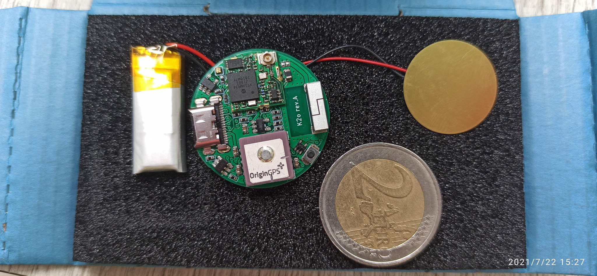
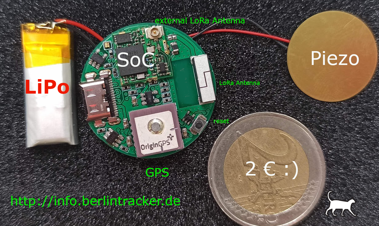
While this started off as a personal DIY project for Peter, it has grown into a global product with a huge following and a growing pre-order list as a testament. Fitted into a coin-sized, circular, 30mm. multilayer PCB, the Kazen tracker is based on the EMB-LR1276S 868 / 915 MHz wireless module which features the ultra-low-power, LoRa enabled, 32-bit Cortex SAM R34 microcontroller and comes pre-configured for communication over LoRaWAN, allowing users to easily connect to individual gateways or networks like TTN.

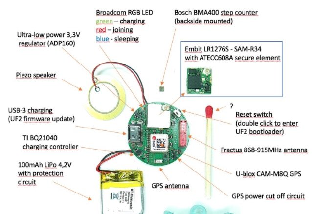
With the EMB-LR1276S taking as little space as possible, the Katzen tracker fits the remarkably small-sized ORG1410 GPS from Origin GPS on the device to acquire location data. To get information on the cat’s movement/activity, the Kazentracker also features the 2mm² miniature low-power, BMA400 tri-axial accelerometer from Bosch.

In addition to the miniature sensors, the device comes with a reset switch, an ultra-low-power 3.3V regulator, and an installed 100 mAH (150 mAH nominal) LiPo battery with a protection circuit and charging controlled by the TI BQ21040 charge controller. For notification purposes, the device features a piezo speaker, Broadcom RGB LEDs, and an electronic ink (e – ink) display, all of which provide feedback to the pet owner via alarms and indication/display of information such as the power status among others.

Key Features and Specifications of the Katzen tracker

  • SoC: Embit LR11276S SoC with integrated LoRa®/LoRaWAN® being compliant with the latest LoRaWAN® specs, along with an integrated crypto unit to protect communication
  • MCU: SAM-R34
  • Power Supply:
    • 5V charging voltage via USB-3
    • Installed 150mAH nominal LiPo Battery
  • GPS: ORG1410 GPS module
  • Accelerometer: Bosh BMA400 tri-axial accelerometer
  • Wireless: LoRa antenna module, external LoRa antenna
  • Misc: Reset switch, piezo speaker

The Katzentracker project is not open source, but useful information about its development and other general details can be found on the project’s Wiki and Twitter pages.

As of the time of this writing, the Cat tracker is not yet available for sale, but Peter has provided a pre-order page for those interested in the device, and manufacturing and delivery are expected to start soon.

PineNote Developer Edition Linux-based Notepad Computer Device at $399

PineNote Developer Edition Tablet

Recently, we covered PinePhone Pro Explorer Edition Linux-based Smartphone built around the Rockchip RK3399S highly integrated with 4GB LPDDR4 RAM and 128GB eMMC flash storage. Pine64 has captured the embedded system news due to the availability of the PinePhone Keyboard case and PineNote Developer Edition. This article primarily focuses on the PineNote Linux-based notepad computer device that is a combination of notebook, tablet, and e-ink panel powered by the Rockchip RK3566 system-on-chip.

As mentioned above, the tablet features RK3566 that comes with a 64-bit quad-core Arm Cortex-A55 processor core clocked at a frequency of 1.8GHz. Moreover, the SoC comes with an embedded Mali G52 2EE GPU, 4GB LPDDR4 RAM, and 128GB eMMC flash storage. These specifications are optimized for it to be one of the fastest Linux-based e-readers on the market. However, the tablet’s internal memory might seem less for multitasking and high-end games.

Specifications of PineNote Developer Edition Tablet

  • System: Rockchip RK3566 featuring 64-bit quad-core Arm Cortex-A55 processor core
  • GPU: Mali G52 2EE
  • Storage: 128GB eMMC flash memory
  • Memory: 4GB LPDDR4 RAM
  • Display:
    • Size: 10.3-inches
    • Resolution: 1404×1872 pixel resolution
    • Touch-type: Capacitive multi-touch panel
  • Wireless connectivity: 2.4/5GHz 802.11a/b/g/n/ac and Bluetooth: 5.0
  • Audio system: Built-in stereo speakers and 4x DMIC interface
  • Battery: 4000mAH LiPo battery
  • Charging: Charging: USB Type-C, DC 5V – 3A
  • Operating system: Not yet ready
  • Dimension: 191.1×232.5×7.4 mm
  • Weight: 438g

PineNote Developer Edition Tablet Interface

At size 10.3-inch, the notebook provides a 1404 x 1872 px resolution with 227 dots per inch and 16 grayscale levels. The capacitive multi-touch panel gives an enhanced user experience with support for the EMR pen digitizer. When it comes to wireless connectivity, the hardware doesn’t stay behind market leaders by supporting IEEE802.11a/b/g/n/ac Wi-Fi and Bluetooth 5.0.

For the audio system, the PineNote Developer Edition offers built-in stereo speakers and a DMIC interface for multiple microphones. When it comes to the battery life of the device, the hardware incorporates a 4000mAh LiPo battery, which can be charged using a DC 5V @3A through a USB Type-C connector.

Important note: As the name says, the PineNote Developer Edition tablet is supposedly only available to developers at this time as the PineNote software is still in the making. Even when the device is officially sold on the store at $399, the tablet is only ready for experienced developers and there is no default OS for the PineNote.

MAX77540 Step-down converter boasts 94 % peak efficiency

The MAX77540 from Maxim Integrated is a high-efficiency step-down converter with two 3 A switching phases.

It uses an adaptive COT (constant on-time) current-mode control architecture, and the two 3 A switching phases can be configured as either one (2Φ, 6 A) or two (1Φ, 3 A each) outputs. Its wide input voltage range enables a direct conversion for sub-1 V outputs from 3-cell Li+ batteries, USB PD, and 12 VDC supply rails.

The output voltages are preset with resistors and are further adjustable through an I2C-compatible interface.

With 94% peak efficiency, low quiescent current, and compact solution size, the MAX77540 is ideal for battery-powered, space-constrained equipment.

Features include 4 V to 16 V input voltage for single-stage conversion and less than 55 mm2 total solution size for high power density.

Applications cover consumer, industrial automation, communications, building and infrastructure, and healthcare

more information: https://www.maximintegrated.com/en/products/power/switching-regulators/MAX77540.html

Abracon ACR1004GC GNSS + GPS L5 Chip Antenna

Abracon ACR1004GC GNSS + GPSL5 Chip Antenna is a compact, low-profile loop antenna that provides centimeter-level accuracy and high efficiency of up to 80%. The ACR1004GC offers L1 peak gain of 2.85dBi and L5 peak gain of 1.91dBi and operates in the 1.166GHz to 1.186GHz and 1.561GHz to 1.61GHz frequencies. Other features include multiband (upper band GNSS + GPS L5), linear polarization, and omnidirectional azimuth pattern. The antenna dimensions are 10mm x 4mm x 1.5mm. Abracon ACR1004GC GNSS + GPS L5 Chip Antenna is ideally suited for M2M, automotive, tracking, and smart applications.

Features

  • Compact, low-profile loop antenna
  • Multiband – upper band GNSS + GPS L5
  • Linear polarization
  • Omnidirectional azimuth pattern
  • High efficiency, up to 80%
  • RoHS/RoHS II compliant
  • Centimeter level accuracy

Applications

  • IoT
  • M2M
  • Automotive
  • Tracking
  • Fleet management
  • Smart agriculture
  • Smart cities

Specifications

  • 1.166GHz to 1.186GHz, 1.561GHz to 1.61GHz operating frequencies
  • 2.85dBi L1 peak gain
  • 1.91dBi L5 peak gain
  • -12dB return loss
  • 50Ω impedance
  • 10mm x 4mm x 1.5mm dimensions
  • -40°C to +85°C operating temperature range

more information: https://abracon.com/datasheets/ACR1004GC.pdf

PWM Temperature Controlled FAN using TC648 and NTC sensor

The project described here is a switch mode fan speed controller for use with brushed or brushless DC motors. Temperature proportional speed control is accomplished using pulse width modulation (PWM). 10K Ohms NTC is used to sense the temperature. The project is built using TC648 chip and configured with auto-shutdown mode. In Auto-Shutdown mode, fan operation is automatically suspended when the measured temperature is lower than 25 degrees centigrade. The fan is automatically restarted and proportional speed control is restored when the temperature exceeds 25 degrees centigrade. An integrated Start-Up Timer ensures reliable motor start-up at turn-on, or when coming out of Shutdown mode. MOSFET Q1 is provided to drive the Fan up to 3A of load. A few fans require a PWM signal to work. Use gate of MOSFET to take out the direct PWM signal.

PWM Temperature Controlled FAN using TC648 and NTC sensor – [Link]

DC-HV DC Converter – 200V @ 20mA Output with 12V DC Input

This is a low-cost DC-HV DC converter built using TL3843 Low-Power Current-Mode PWM Controller from TI. Screw terminal connectors are provided for input and output, onboard LED D1 indicates the input supply. The project provides 200V DC @ 20mA output from 12V DC supply input.

DC-HV DC Converter – 200V @ 20mA Output with 12V DC Input – [Link]

TinyML Image Classification On ESP32-CAM Development Board and Edge Impulse Studio

TinyML Image Classification

Recent breakthroughs in embedded machine learning have increased the demand for TinyML applications. In dealing with TinyML, there is an excellent platform to get started and build complex projects, Edge Impulse. We have also witnessed several new embedded devices coming to market primarily designed with TinyML capabilities. This is only possible because of the support from the communication in solving some of the really critical problem statements.

[Marcelo Rovai] published a detailed write-up on learning image classification on embedded hardware, ESP32-CAM, and showcasing the flexibility brought in by the affordable and powerful development board. As Edge Impulse has captured the market for TinyML easy implementation, the embedded developer has decided to use Edge Impulse Studio for the software side. Circling back to the hardware, ESP32-CAM incorporates the Espressif’s ESP32-S microcontroller chip along with a highly integrated ArduCam OV2640 camera.

Supporting I2C, SPI and UART communication give the opportunity to interface external devices and sensors. Since the hardware does not have a USB-TTL serial module for programming, the maker uses a special adapter to upload the load onto the ESP32-CAM. For those unfamiliar with the ESP32-CAM module, the hacker recommends referring to some of the online resources publicly available with a highlight on the books and tutorials of Rui Santos.

TinyML Image Classification Hardware

Starting with the software side of the TinyML Image Classification project, the initialization of the ESP32-CAM development board onto the Arduino IDE is the same as done for other setups. The first thing for any hardware development project is to test the board by blinking the LED. For the employed hardware, the built-in LED is connected with GPIO33, which will ease the code building process. For this specific project, [Marcelo Rovai] also decides on testing the Wi-Fi wireless communication and the onboard camera.

With TinyML, a set of technics associated with machine learning inference on embedded devices, we should limit the classification to three or four categories due to limitations (mainly memory in this situation).

Training the model with Edge Impulse Studio has a dataset containing images of several fruits and vegetables with each category being split into train, test, and validation with 100, 10, and 10 images respectively. The model in this case reached an accuracy of 77%, which is decently good for the amount of RAM on the ESP32-CAM development board. Once the software is uploaded to the hardware, the setup seems to work perfectly fine, just as expected for the initial goal.

For more details on the TinyML Image Classification project, visit the complete write-up on the Hackster project.

Meet the All New Orange Pi 3 LTS

Shenzhen-based electronics manufacturer; Xunlong Software Co., has announced the release of the latest member of its Orange Pi Family; The Orange Pi 3 LTS, designed for projects that require SBCs with high processing power but highly compact form factor.

Built around the Allwinner H6 SoC which features the Quadcore 64bit, 1.8 GHz Arm Cortex-A53 processor, the Orange Pi 3 LTS provides a slimmed-down version of the Orange Pi 3 with a few features, like the multiple USB ports, PCIE interface, and others from the original Orange Pi 3, sacrificed to reduce the size of the board and keep cost low.

Fitted into a Raspberry Pi like 85 x 56mm form factor, the Orange Pi 3 LTS features the high-performance, multi-core GPU Mali T720 with OpenGL, DirectX, ASTC, and support for Floating point operation greater than 70 GFLOPS. It also comes with a 2GB LPDDR3 shared by the CPU and GPU, and 8GB eMMC flash, and an onboard Allwinner AW859A, which replaces the Ampak AP6256 on the previous version, providing WiFi and Bluetooth 5.0.

For Interfaces, the Orange Pi 3 LTS replaces both the DC jack and micro-USB OTG port on the original OPI 3 with a USB Type-C input, and the 4x USB 3.0 ports and single USB 2.0 port with a single USB 3.0 and dual USB 2.0 ports. The board retains the 4K-ready HDMI 2.0 port alongside the GbE, the TV CVBS video output port / A/V jack, mic input, 26-pin GPIO, IR receiver, and a microSD slot.

The features and specifications of the Orange Pi 3 LTS are highlighted below:

  • SoC: Allwinner H6: Quad-core, 64-bit 1.8GHz Cortex-A53 processor with multi-core GPU Mali T720 supporting OpenGL ES3.1/3.0/2.0/1.1, Microsoft DirectX 11 FL9_3, ASTC, Floating point operation greater than 70 GFLOPS
  • Memory: 2GB LPDDR3 (shared with GPU)
  • Storage: 8GB EMMC Flash
  • Power Source: 5V/3A via USB-C
  • Controls Systems:
    • AXP805 Chip for power management
    • YT8531C Network Chip that supports 10/100M/1000M Ethernet
  • Wireless Connectivity:
    • AW859A WIFI+Bluetooth Chip
    • Support IEEE 802.11 a/b/g/n/ac
    • Support BT5.0
    • IR Receiver for IR remote control
  • Multimedia:
    • Video:
    • HDMI 2.0a output
    • TV CVBS output
  • Audio:
    • HDMI Output
    • 3.5mm Audio output port
  • Expansions/Connectors:
    • Micro SD card slot
    • USB: 1x USB 3.0 host, 2x USB 2.0 host
  • Peripherals (low-level): 26pin connector with 1x SPI, Multiple GPIOs,1x I2C, 1x UART
  • Misc:
    • Power button (SW4), Power LED, Status LED
  • OS:
    • Supports Android 9.0, Ubuntu, and Debian
  • Dimension: 56mm*85mm

The Orange Pi 3 LTS is compatible with Android 9.0, Ubuntu, and Debian Operating systems.

The SBC is currently available for purchase for $35.00 on AliExpress and Amazon store, and since it is open source, docs such as schematics and other open hardware resources are expected to be released on Github soon.

More information on the Orange Pi 3 LTS can be found on the OrangePi website.

Meet the Biomedical-Lab-On-Chip from Onera; An Ultra-Low-Power Biomedical Sensor Hub

MedTech Company, Onera Technologies in league with IMEC recently announced the launch of its latest product; the Onera Biomedical-Lab-On-Chip – an ultra-low-power biomedical sensor hub, designed to accelerate the development of wearable health devices.

Announced barely two days to the just concluded CES 2022, the biomedical system-on-chip is the first in the class by Onera, following its celebrated sleep diagnostic solutions, and it embeds clinical-grade physiological measurements and analysis systems to revolutionize the development of high-grade miniaturized wearable devices.

Based on Arm Cortex – M4f CPU, the Onera Biomedical-Lab-On-Chip is equipped with a multi-channel sensor readout system along with built-in power management, data processing, and interfacing features. It supports on-chip biomedical sensing and data retrieval with ten readouts for ExG, including EEG, ECG, EMG, EOG, and two readouts for photoplethysmography along with two bioimpedance readouts. The chip also embeds a 320kB SRAM and 768kB flash, along with embedded digital filters and an accelerator block which features a data compactor, sampling block, processor, FIFO, and DMA and synchronization engines all of which facilitate on-chip data processing and support for a broad range of wearable health applications and devices.

Designed for use in wearable devices and applications across the medical health and wellness industry, the Biomedical-Lab-on-Chip features digital interfaces like SPI, I2C, I2S, UART, and GPIOs which aids its integration with other subsystems.

Key features and specifications of the biomedical sensor hub SoC include:

  • CPU:
    • Arm Cortex – M4f with DSP, FPU, 3x AHB – Lite, JTAG, supporting ITM trace, Data watchpoint, Nested Vectored Interrupt
  • Power Input: 0.8V – 3.6V (single supply)
  • Memory: 320 kB SRAM
  • Storage: 768 kB flash
  • Analog Readouts: 
    • 10x ExG including EMG, ECG, EOG, and EEG; 2x PPG – photoplethysmography, 4x LED drivers, 2x Bioz MF, 2x Bioz CG
  • Digital Interfaces:
    • 4x SPI, 4x I2C, 2x I2S, 2x UART, 48x GPIO
  • Accelerators:
    • Matrix processor, Sample rate, Data compactor, DAT synchronization, FIFO, DMA
  • Misc:
    • System timing, Power management: 2x HP LDO @ 50mA, 2x LDO and Buck -boosters (7x outputs)

Onera plans to make the Biomedical-Lab-on-Chip available for commercial use to all and sundry and while there is no clear distribution/price information yet, it is said to be in the works and should hit the shelves soon.

More information on the Biomedical Sensor Hub SOC and other giant strides by Onera can be found on Onera’s website.

NEXCOM Unveils X200 Embedded Computer Board For Healthcare Applications

X200 Embedded Computer Board

Taiwan-based embedded electronic device manufacturer, NEXCOM has unveiled a 3.5-inch embedded computer board, X200, built around the 11th Generation Intel Core Processor. Decently sized high-performance computer is designed to bring in digital transformation in AI image processing specifically in the health care industry. Powerful graphic processing capabilities render 4K for multiple displays with ease of use. Additionally, advanced wireless communication flexibility has brought in the scope for its deployment in a variety of applications.

The X200 embedded mini-computer board has three versions based on Intel’s processor core varying from 11th Generation Intel i3 processor core to i7 quad-core processor. However, note that the i7 processor variant will only be available on individual requests. Moreover, the Intel UHD graphics on the i3 processor and Iris Xe graphics on the i5 processor makes it an intelligent solution for AI image processing. The hardware comes with rich I/O interfaces for several external and internal connections.

Specifications of X200 Embedded Computer Board

  • System:
    • 11th Generation Intel dual-core i3-1115G4E processor @2.2 GHz base clock frequency
    • 11th Generation Intel dual-core i5-1145G7E processor @1.5 GHz base clock frequency
    • 11th Generation Intel quad-core i7-1185G7E processor @1.8 GHz base clock frequency,
  • Memory: 1x 260-pin DDR4 SO-DIMM, supports non-ECC, and un-buffered memory up to 32 GB
  • Storage:
    • 1x M.2 2280 Key M, support PCIe x4 (512GB Maximum)
    • 1x SATA 3 & SATA power connector for optional 2.5-inch SSD
  • Wireless communication:
    • 1 x Intel I219-LM GbE PHY, support Intel vPro platform technology (for Intel® Core™ i5 or above processor)
    • 1 x Intel I211-AT GbE LAN
  • Graphics:
    • Intel UHD graphics on i3 processor
    • Intel Iris Xe graphics on i5 processor
    • 1x DP++, support 4096 x 2304 @60Hz
    • 1x HDMI 2.0, support 4096 x 2160 @60Hz
    • 1x eDP, support 4096 x 2160 @60Hz
  • Interfaces:
    • 4x USB 2.0, internal connector
    • 1x Mic-in, 1x Line-out, internal connector
    • 1x Speaker-out with 2W/4Ω amplifier, internal connector
    • 6x GPIO pin header for 3 x GPI and 3 x GPO
    • 1x 4-pin connector for PWM smart FAN
    • 1x 12V, 2A power output coming from the main power source for additional module use
    • 1x eDP: support 4096 x 2160 @ 60Hz
    • Onboard TPM 2.0 (for SKU X200-i5)
    • 1x RS232/422/485, internal pin header (COM1)
    • 1x RS232, internal pin header (COM2)
  • Expansion: 1x M.2 2230 Key E, support optional Wi-Fi modules
  • Power:
    • 12V DC input via DC Jack
    • 2-Pin internal DC input connector as the option
  • Software support: Windows 10 and Linux
  • Operating temperature: -20°C to 70°C
  • Dimensions: 146×102 mm

X200 Embedded Computer Board Block Diagram

Visual inspection and diagnosis from the use of medical images can be done through the AI processing capabilities of the X200 embedded computer board. The support for 4K at 60Hz frequency gives the hardware a reduction in latency and easy to make decisions through imagery for preliminary checkups. Also, through support for SATA connectors for 2.5-inch SSD offering expandable storage capacity. The hardware also supports up to 32GB of SRAM through SATA 3 and SATA power connectors.

The 4K flawless imaging brings even the smallest details in x-ray films to life, making automatic detection of abnormal x-ray imaging a reality. This form of visual inspection can assist healthcare professionals in increasing overall efficiency, making more accurate/reliable decisions and misdiagnosis prevention, ultimately, saving more valuable lives than ever.

Currently, the manufacturer has not publicly disclosed any information on pricing. However, you are advised to send an inquiry for more details on the availability. Head to the product page for more information on the capabilities and technical specifications.

TOP PCB Companies