To help you increase the breadth of models you offer to your customers, we added over 1 million parts to SnapEDA from manufacturers like Samtec, Panasonic, Texas Instruments, Telit, PUI Audio, Laird, Azoteq, Traco Power, Micro Crystal, among others, that include electromechanical models, connectors, passive and active components, resistors, etc.
New formats added
We increased our supported PCB design formats to 20 formats. In 2021 alone we added 7 new formats including DipTrace, DesignSpark, Autodesk Fusion 360 Zuken eCADSTAR, Zuken CR-5000 & CR-8000, ExpressPCB Plus. This means you’ll be able to support engineers across even more tools
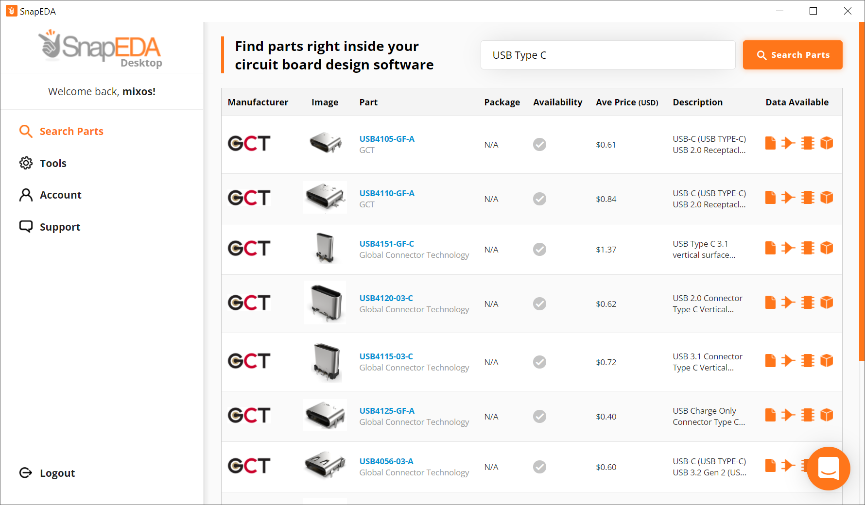
New desktop app to help engineers design faster
At SnapEDA, we are always looking for ways to make the design process even easier for engineers. We started hearing a lot of feedback from our community that they wanted to place parts in their CAD tools like magic and we heard them! We introduced our new desktop app to help engineers auto-import parts from the web seamlessly without extra steps. Learn more here
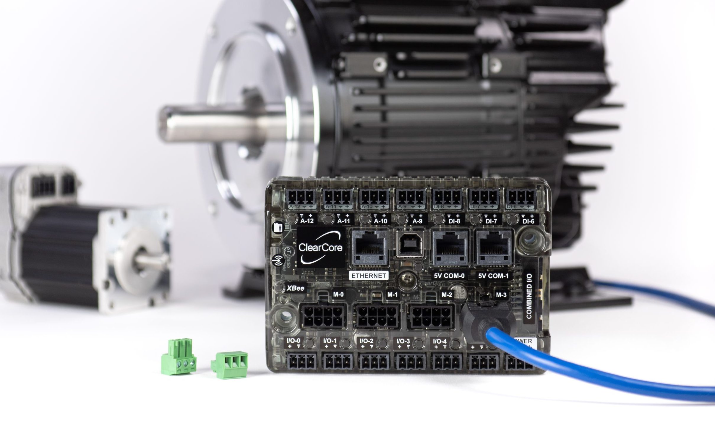
Teknic’sClearCore, a low-cost, multi-axis, motion and industrial I/O controller, now has Modbus communication. ClearCore provides 4 axes of motion control, Ethernet, serial, USB, and wireless expandability along with 13 configurable digital & analog I/O points. Accelerate your development with more than 40 example projects, including a new Modbus HMI example project. Teknic’s Modbus project contains wiring information, example code, and open source Modbus libraries.
Key specifications and benefits of ClearCore include:
Hardware includes a powerful 32-bit, floating point ARM Cortex-M4 processor, 192k local RAM, 512k Flash, interrupt handler, and an onboard SD Card interface for storage expansion.
ClearCore provides up to 4 axes of motion control for Teknic’s ClearPath integrated servos, 3rd party stepper drives, or any brushless servo motor with a digital servo drive.
ClearCore includes 13 industrially hardened and electrically conditioned, 24V I/O points, including digital and analog inputs and outputs. Extend your I/O compliment with 8-point I/O expansion modules (CCIO-8) for a total I/O compliment of 73 I/O points.
Compatible with XBee modules for peer-to-peer wireless communications such as WiFi, Bluetooth, ZigBee, DigiMesh, 802.15.4, and others.
A rich C++ library & software API including more than 40 extensively commented example projects ensures ease-of-use and accelerates your development cycle. Teknic’s new Modbus project contains example code, wiring information, and open source Modbus libraries.
All source code is available for free, under an open-source, copy-right, MIT license; compatible with the Arduino IDE for rapid software prototyping.
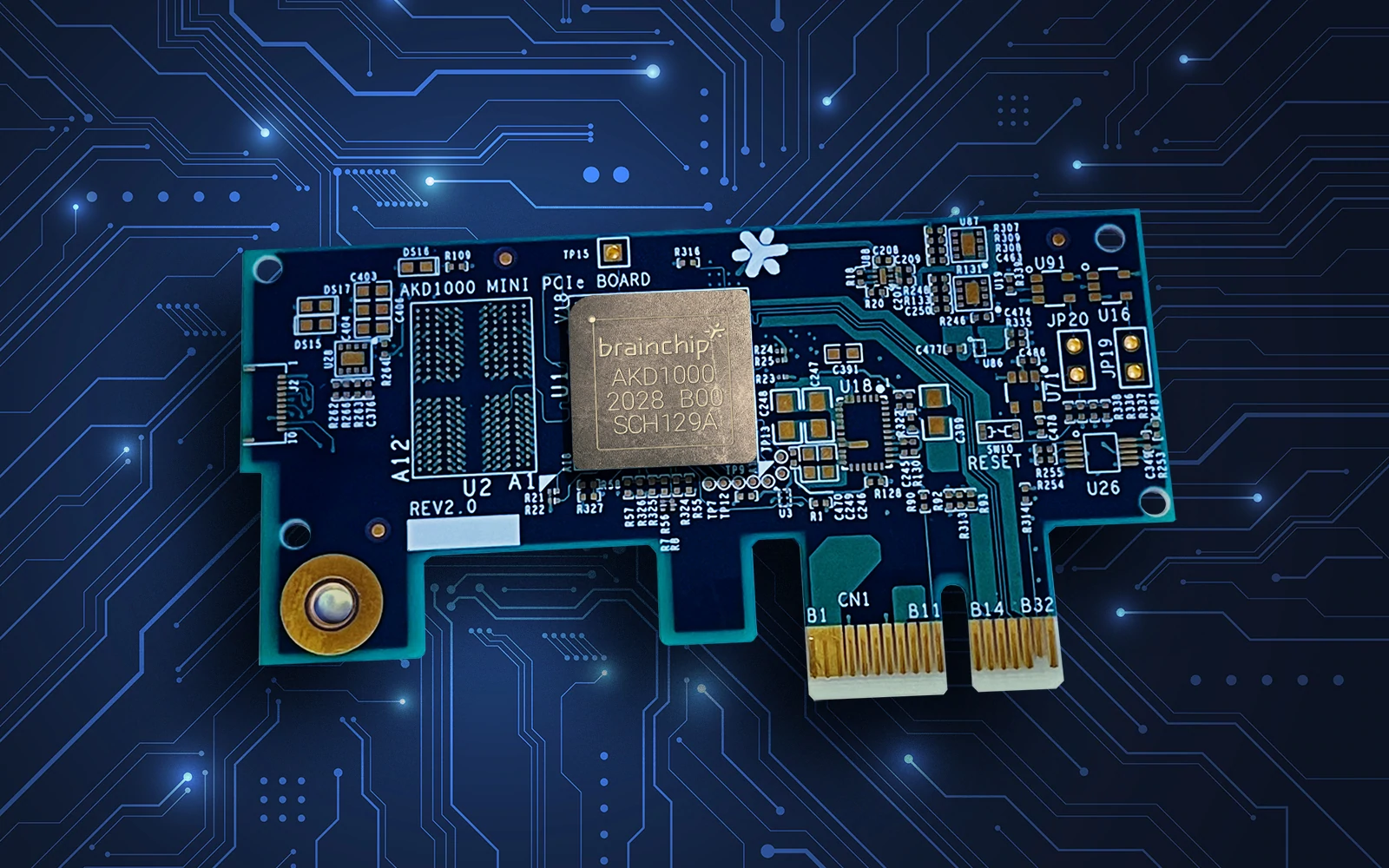
PCIe board based on an advanced neural networking processor enables AI training and learning on the device itself, without dependency on the cloud. [via]
Brainchip has begun taking orders for the first commercially available Mini PCIe board using its Akida advanced neural networking processor.
The $499 AKD1000-powered Mini PCIe boards can be plugged into a developer’s existing system to unlock capabilities for a wide array of edge AI applications, including Smart City, Smart Health, Smart Home and Smart Transportation. BrainChip will also offer the full PCIe design layout files and the bill of materials (BOM) to system integrators and developers to enable them to build their own boards and implement AKD1000 chips in volume as a stand-alone embedded accelerator or as a co-processor.
The boards provide the ability to perform AI training and learning on the device itself, without dependency on the cloud. The production-ready chips provide high-speed neuromorphic processing of sensor data at a low cost, high speed and very low power consumption with in-built security.
“We have been working on developing our Akida technology for more than a decade and with the full commercial availability of our AKD1000, we are ready to fully execute on our vision,” said Sean Hehir, BrainChip CEO. “Other technologies are simply not capable of the autonomous, incremental learning at ultra-low power consumption that BrainChip’s solutions can provide. Getting these chips into as many hands as possible is how the next generation of AI becomes reality.”
The launch of BrainChip’s new PCIe board closely follows the company’s development kit offerings introduced in October. The two development kits – an x86 Shuttle PC development kit, as well as an ARM-based Raspberry Pi development kit – both include the AKD1000 chip on a Mini PCIe board and are available to partners, large enterprises and OEMs.
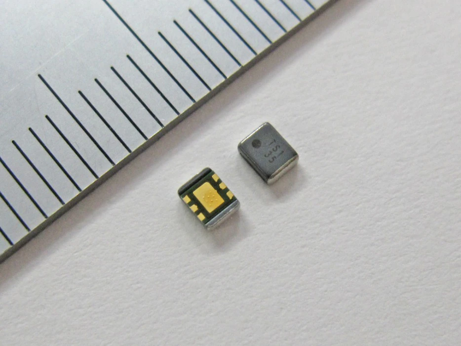
Torex Semiconductor Ltd. has launched the XCL232 which is a new series of inductor built-in step-down DC/DC converter.
The XCL232 series is a synchronous step-down micro DC/DC converter which integrates an inductor and a control IC in one tiny package.
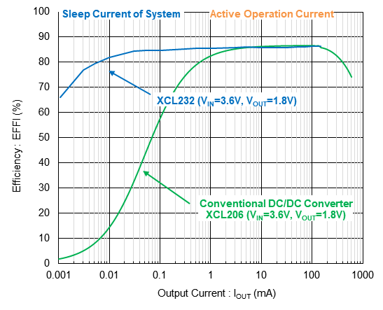
The efficiency performance at a light load current is dramatically improved by implementing ultra-low power consumption circuits which has 200nA consumption current, and PFM control method. In particular, the efficiency at an output current of several μA to 10 μA has been improved by 70% or more compared to conventional products (Fig. 1). Compatible with low consumption MCUs and SoCs. In addition, a low output voltage from 0.5V can be selected, makes it ideal for low voltage SoCs.
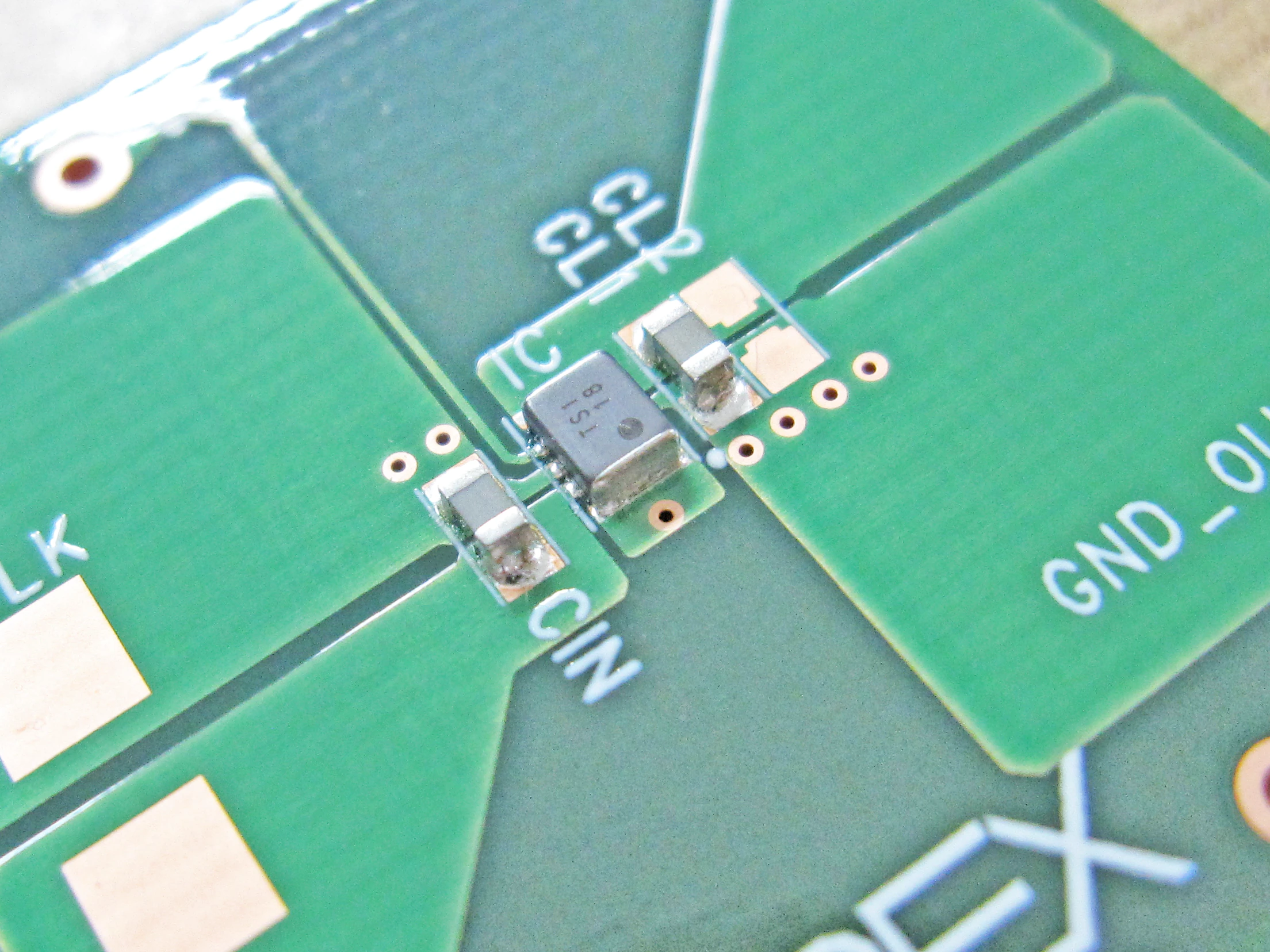
By Integrating control IC and coil, it makes it possible to achieve ultra-compact, high efficiency from light load, and low EMI by simply attaching two small ceramic capacitors externally,with making it easy for customers to design we support customers strongly.
The XCL232 series are suitable for IoT/mobile/wearable and all devices that place emphasis on emphasize better life where small size, saving area , high efficiency performance at a light load current are important.
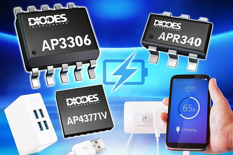
Diodes Incorporated provides a high-efficiency, small footprint solution for USB PD3.0 chargers
The AP3306, APR340, and AP43771V combination from Diodes Incorporated provide a high-efficiency, small footprint solution for USB PD3.0 chargers. The AP3306 active clamp flyback (ACF) controller uses a non-complimentary high- and low-side control mechanism to achieve leakage energy recycling and zero voltage switching (ZVS) for supreme-efficiency performance and can meet <30 mW standby loss. The APR340 is a secondary-side synchronous-rectification MOSFET driver optimized to work with the AP3306. The AP43771V is a USB Type-C® Power Delivery (PD) 3.0 PPS decoder. It is compliant with both USB PD specification Rev 3.0 V1.1 (TID – 4305) and QC4/4+/QC5 (certification by GRL). The AP43771V (QFN-24) maximizes power usage by using its I²C interface and GPIO pins to facilitate operation in multi-port independent-output voltages where built-in smart-power-sharing firmware is implemented. Based on quick-charger designs to shorten design-to-production cycle time, the AP43771V has 45 W and 65 W single-C and dual-C reference designs for USB PD3.0 PPS.
Features
AP3306 ACF controller
Supports high-side switcher driver without level-shift circuitry, and non-complimentary high- and low-side control mechanisms to reduce BOM cost and simplify system design
AP43771V decoder
Supports a cost-effective and flexible program mode:
One-time programmable ROM is provided for main firmware
Multi-time-programmable ROM is provided for user-configuration data
Uses an I²C interface and a built-in smart-power sharing scheme:
Supports multiple USB Type-C port-independent voltage-output charging applications (QFN-24) for power-usage optimization
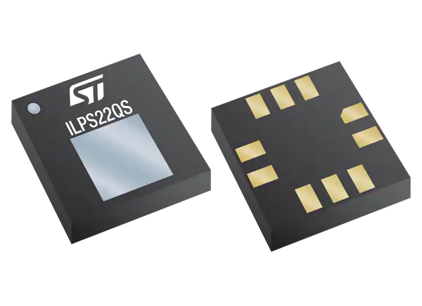
STMicroelectronics ILPS22QS Absolute Digital Output Barometer is an ultra-compact piezoresistive absolute pressure sensor that operates as a digital output barometer. The ILPS22QS supports dual full-scale up to user-selectable 4060hPa. The ILPS22QS features ultra-low pressure noise with very low power consumption.
The STM ILPS22QS Absolute Digital Output Barometer combines a sensing element and an IC interface that communicates over I2C, MIPI I3CSM, or SPI interfaces from the sensing element to the application. The sensing element that detects absolute pressure consists of a suspended membrane manufactured using a dedicated process developed by ST.
The ILPS22QS is offered in a full-mold, holed LGA package (HLGA) and operates over an extended temperature range from -40°C to +105°C. The LGA package is holed to allow external pressure to reach the sensing element.
Features
Selectable dual full-scale absolute pressure range
Mode 1 at 260hPa ~ 1260hPa
Mode 2 at 260hPa ~ 4060hPa
Current consumption down to 1.8µA
0.5hPa absolute pressure accuracy
0.34Pa low-pressure sensor noise
High-performance TCO at 0.45Pa/°C
Embedded temperature compensation
Extended temperature range from -40°C to +105°C
24-bit pressure data output
ODR from 1Hz to 200Hz
SPI, I2C, or MIPI I3CSM interfaces
Supports 1.08V digital interface
Embedded FIFO
Embedded analog hub for processing analog input data
Embedded Qvar for detecting electric charge variation
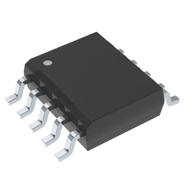
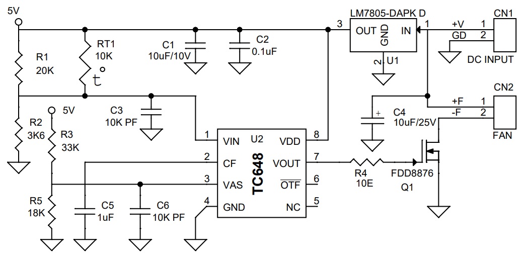
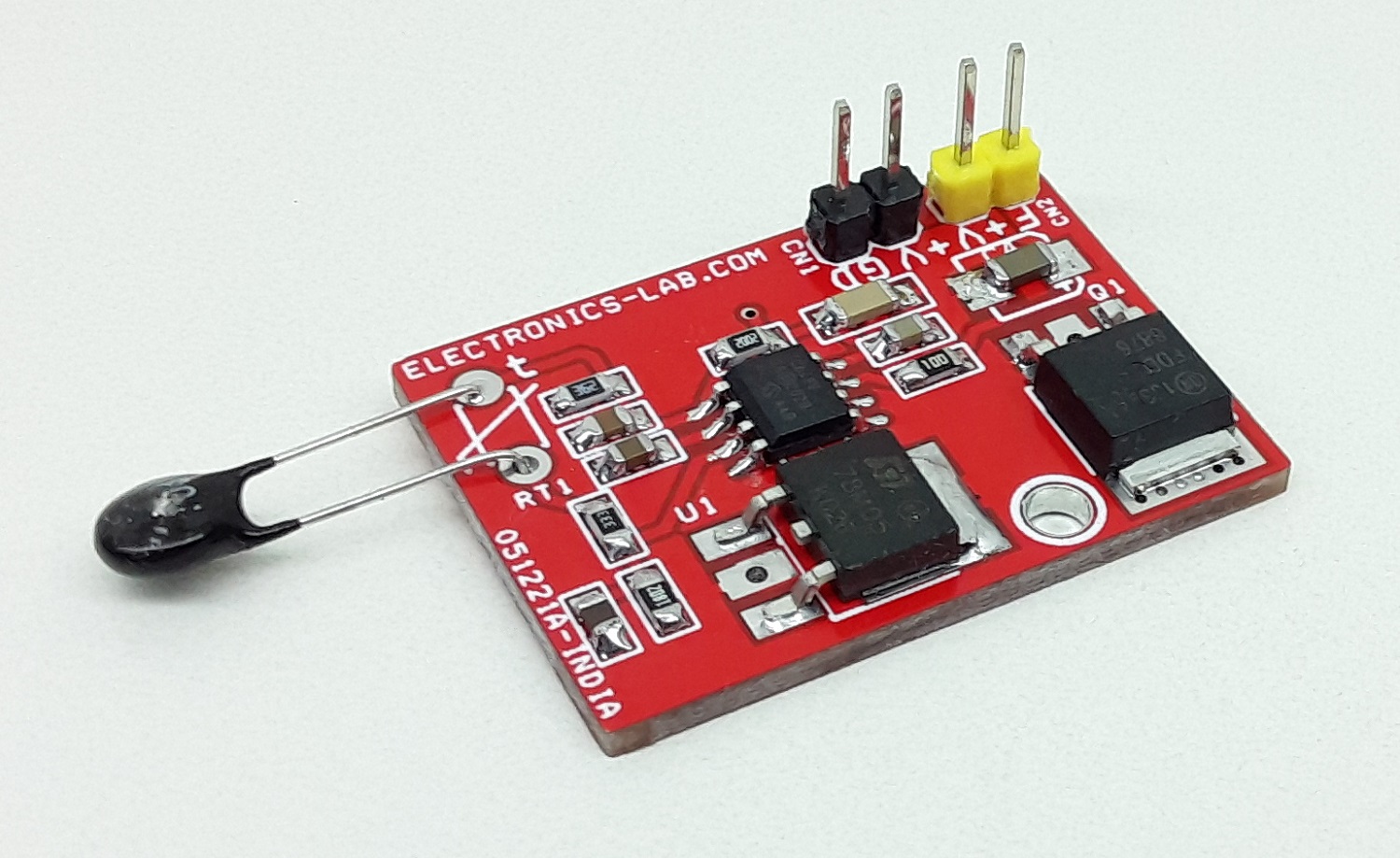
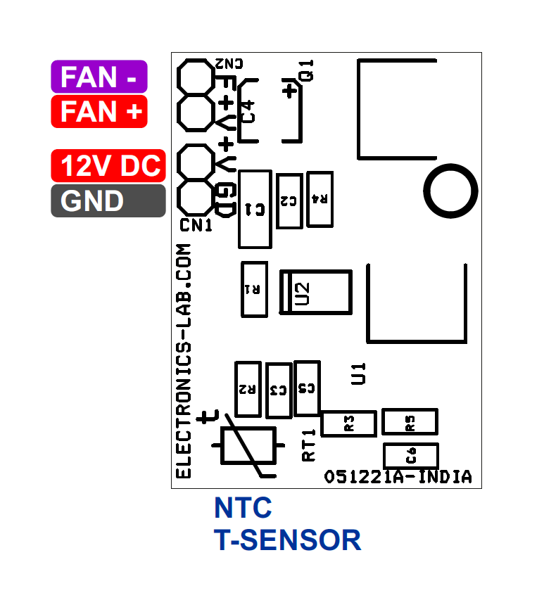
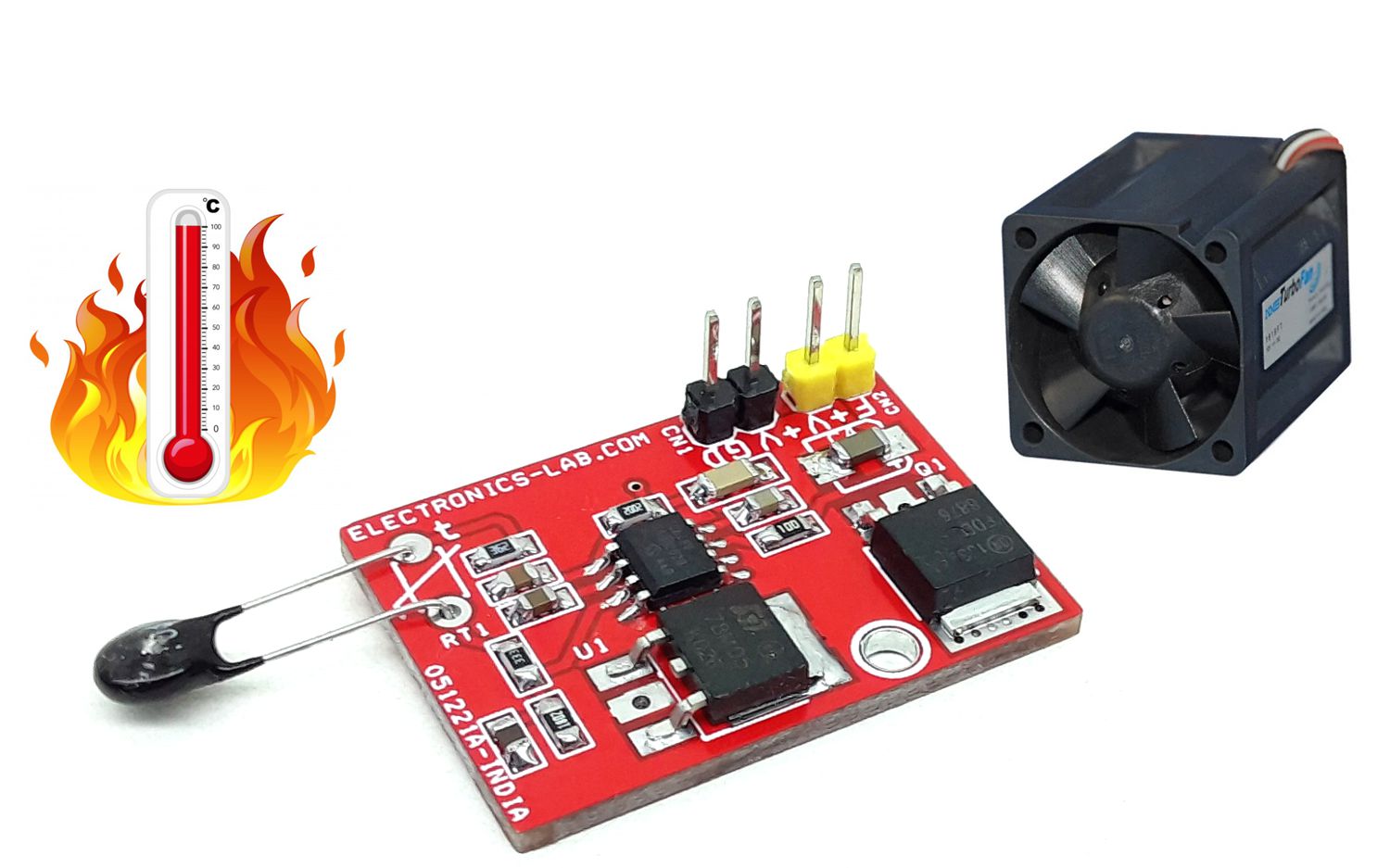
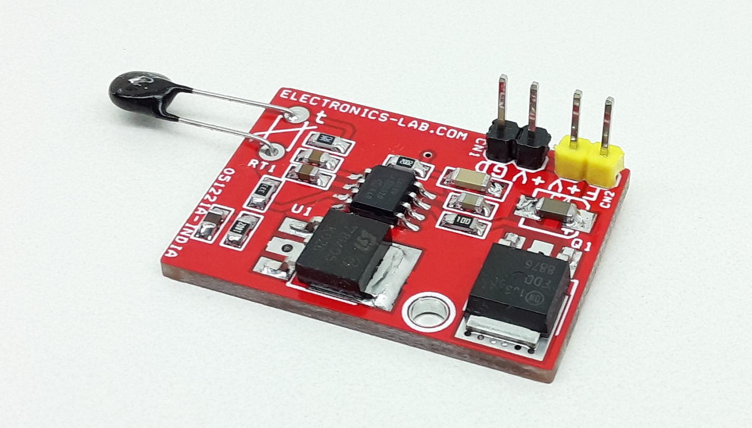
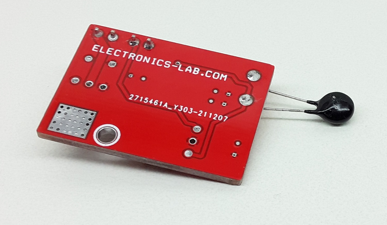
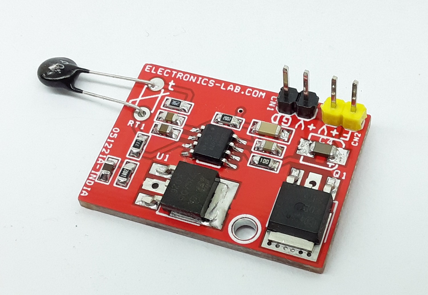
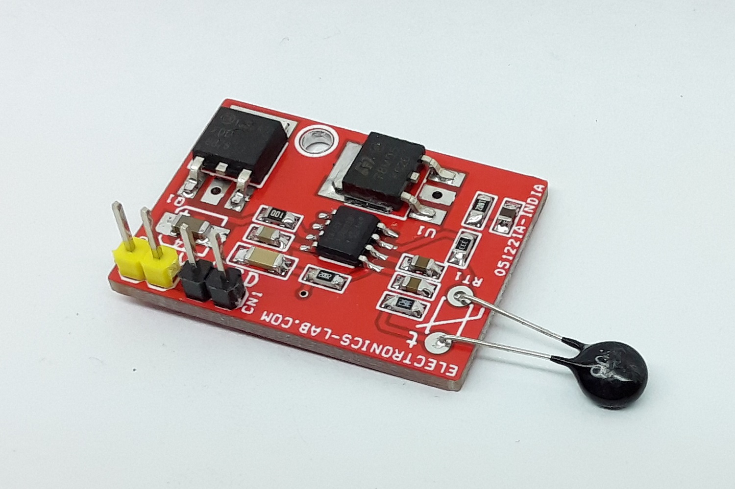
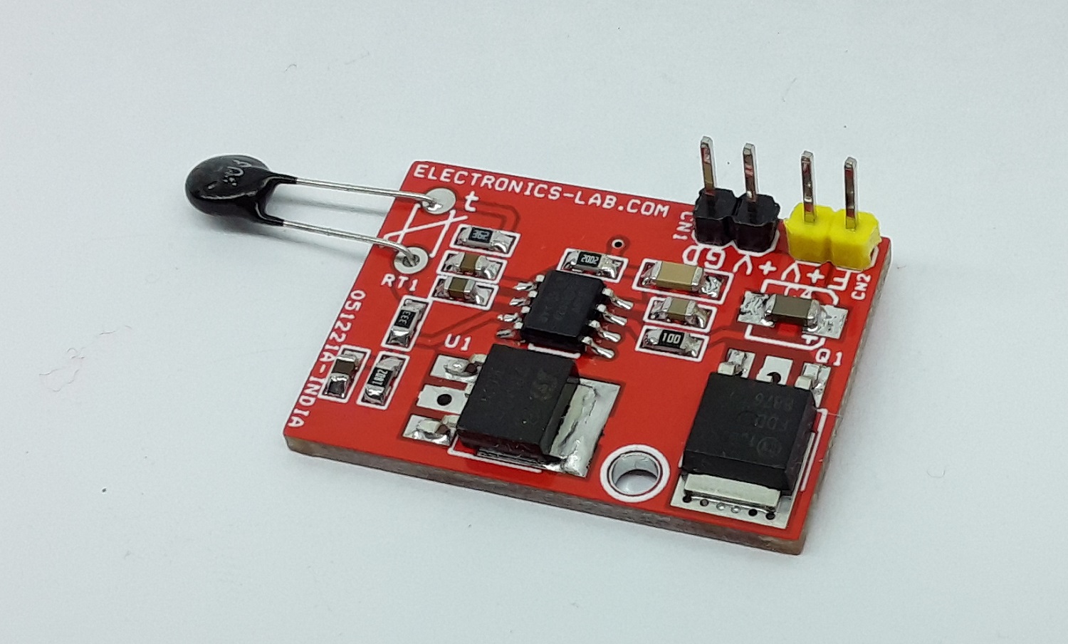
The project described here is a switch mode fan speed controller for use with brushed or brushless DC motors. Temperature proportional speed control is accomplished using pulse width modulation (PWM). 10K Ohms NTC is used to sense the temperature. The project is built using TC648 chip and configured with auto-shutdown mode. In Auto-Shutdown mode, fan operation is automatically suspended when the measured temperature is lower than 25 degrees centigrade. The fan is automatically restarted and proportional speed control is restored when the temperature exceeds 25 degrees centigrade. An integrated Start-Up Timer ensures reliable motor start-up at turn-on, or when coming out of Shutdown mode. MOSFET Q1 is provided to drive the Fan up to 3A of load. A few fans require a PWM signal to work. Use gate of MOSFET to take out the direct PWM signal.
Auto-Shutdown Setting (Resistor Divider R3 and R5)
An external resistors R3 and R5 divider connected to the VAS input sets the auto-shutdown threshold. Auto-shutdown occurs when VIN ≤ VAS. During the shutdown, the supply current falls to 25 µA (typical). The fan is automatically restarted when VIN ≥ (VAS +VHAS).
PWM (Duty Cycle 42% to 100%, 42% is setpoint for minimum speed beyond this shutdown event occurs)
The PWM circuit consists of a ramp generator and threshold detector. The frequency of the PWM is determined by the value of the capacitor connected to the CF pin. A frequency of 30 Hz is selected using CF capacitor C5, PWM is also the time base for the Start-up Timer. The PWM voltage control range is 1.25V to 2.65V (typical) for 0% to 100% output duty cycle.
Start-Up Timer
To ensure reliable fan start-up, the Start-up Timer turns the VOUT output on for 32 cycles of the PWM whenever the fan is started from the off state. This occurs at power-up and when coming out of shutdown or auto-shutdown mode. Start-up time is approximately one second with PWM frequency 30Hz)
Auto shut-Down Mode Calculation
Calculation R1 and R2 based on using an NTC having a resistance of 10 kΩ at TMIN (25°C) and 4.65 kΩ at TMAX (45°C) R1 = 20 kΩ R2 = 3K6 kΩ
Set auto-shutdown level. VAS = 1.8V Limit the divider current to 100 µA R3 = 33 kΩ R5 = 18 kΩ
Note: This board operates in auto-shutdown mode, but it can also be configured as minimum speed mode, refer to datasheet for configuration. Various speed (Duty Cycle) VS Temp range can be achieved by changing resistor value, refer to the datasheet of the chip for equations.
Features
Operating Supply 12V to 18V
Fan 12V – 18V DC
Load up to 3A (12V to 18V)
PWM Duty Cycle 42% to 100%
Fan Shut-down when Temperature Falls approx. 25 Degree Centigrade
Fan Low Speed (42% Duty Cycle) When Temperature 25 Degree Centigrade
Fan Full Speed (100% Duty Cycle) When Temperature goes Above approx. 45 Degree Centigrade
PWM Frequency 30 Hz
Temperature Proportional Fan Speed for Acoustic Control and Longer Fan Life
In the previous articles, it has been shown that the digital logic gate and digital circuit can be represented by a Boolean expression and a truth table. A Boolean expression consists of a number of variables representing inputs and an output which is usually represented by a “Q”. The inputs and outputs have Boolean logic data type i.e. either “0” or “1”. The Truth Table lists the output of the logic gate or digital circuit against all the possible combinations of inputs. Using the Boolean algebra and laws of Boolean algebra, the complex digital logic circuits can be reduced.
The identification and replacement of unnecessary logic gates lead to saving space, cost and power. The reduction process of a complex digital logic circuit can have multiple paths depending on the application of laws and theorems etc. However, the reduction paths should yield a similar and simplest circuit if Boolean algebra and laws are applied correctly.
In this article, a few digital logic circuits are reduced using the application of Boolean algebra and laws. The reduction process has been explained and truth table(s) are also given to aid the explanation and reduction process.
Boolean Algebra Example No. 1
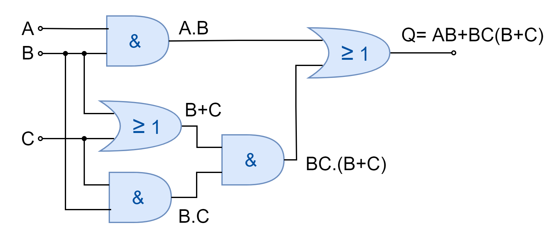
In the following figure, a digital logic circuit is shown. The circuit consists of three AND gates and two OR gates. A total of five gates are required to produce the desired logic function. In this example, the desired logic function is reduced by applying Boolean Algebra Laws and Theorems.
Figure 1: Digital Logic Circuit of Example No. 1
The steps involved in the reduction of Boolean expression are as follow:
AB + BC(B+C)
Applying Distributive Law
AB + BBC + BCC
Applying Identity Law (AA=A) to 2nd and 3rd terms
AB + BC + BC
Applying Identity Law (A + A = A) to 2nd and 3rd terms
AB + BC
Taking out common B
B(A+C)
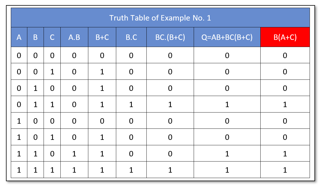
The reduced expression B(A+C) produces the same logical output as of original expression. The truth table of the original Boolean expression as well as of reduced expression (red) is shown below:
The reduced expression requires only two logic gates i.e. AND, and OR gates. A reduction in three gates has been achieved by applying Boolean Algebra Laws to a complex expression. The simplified logic circuit diagram is shown in the following figure.
Figure 2: Solution of Example No. 1
Boolean Algebra Example No. 2
In the following figure, another digital logic circuit is shown.
Figure 3: Digital Logic Circuit of Example No. 2
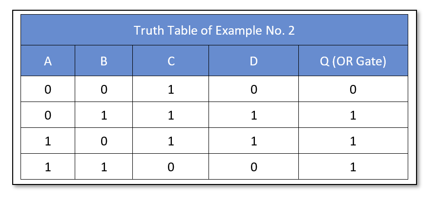
The given digital circuit consists of a total of three logic gates i.e. NAND, XOR, and XNOR. This digital circuit is being reduced by constructing a truth table. The truth table constructed is then analyzed to identify single logic to replace the output. The 2-input gives four combinations and is easy to construct. For such kinds of digital circuits, the truth table technique is more feasible. The following table is constructed easily by knowing the truth table of the individual gates. The output “C”, “D”, and “Q” corresponds to NAND, XOR, and XNOR, respectively. The outputs “C” and “D” become the input of the XNOR gate.
The truth table generated is shown below:
The output of the digital logic circuit is “HIGH” when any of the inputs “A” or “B” is “HIGH”. This expression or output is given by a digital OR gate. Hence, the given three logic gate circuit can be reduced to a single OR gate with inputs “A” and “B”. The simplified logic circuit having the same output as the original digital circuit is shown below:
Figure 4: Solution of Example No. 2
Boolean Algebra Example No. 3
In the following figure, another logic circuit is shown.
Figure 5: Digital Logic Circuit of Example No. 3
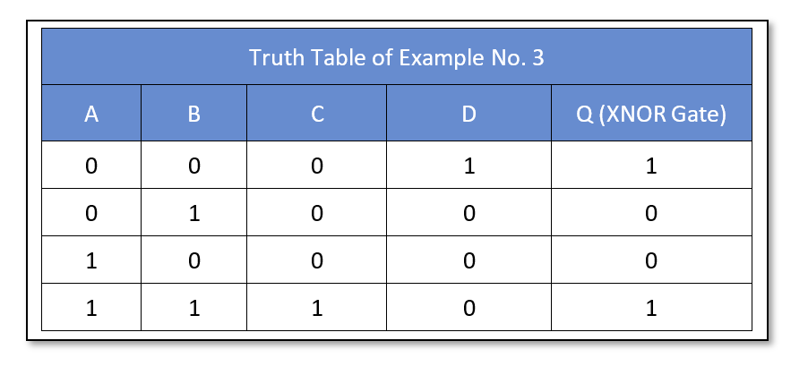
The digital logic circuit comprises three logic gates i.e. AND, NOR, and OR. The output of the NOR is converted to the product of inversed individual input. The final output of the OR gate which is the function of the whole logic circuit comes to be equivalent to the function of XNOR logic. Hence, the given three gates digital logic circuit can be replaced by a single gate of Exclusive-NOR gate.
The truth table technique has also been adopted to obtain a single gate equivalent. The truth table has been constructed and shown below:
The circuit’s final output “Q” is equivalent to Exclusive-NOR gate output. The truth table also identifies the Exclusive-NOR as a single-stage equivalent of the given logic circuit. The Exclusive-NOR (XNOR) gate with two-inputs “A” and “B” has shown in the following figure.
Figure 6: Solution of Example No. 3
Boolean Algebra Example No. 4
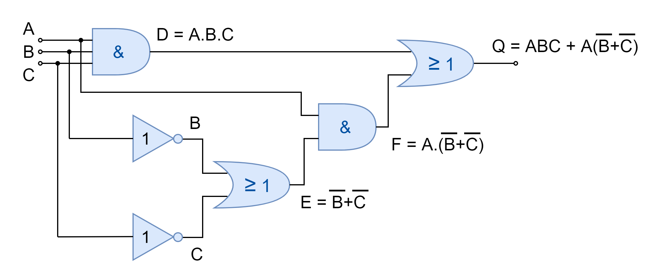
In the final example, a more complex digital logic circuit has simplified which consists of six logic gates. The logic circuit to be reduced has been shown below.
Figure 7: Digital Logic Circuit of Example No. 4
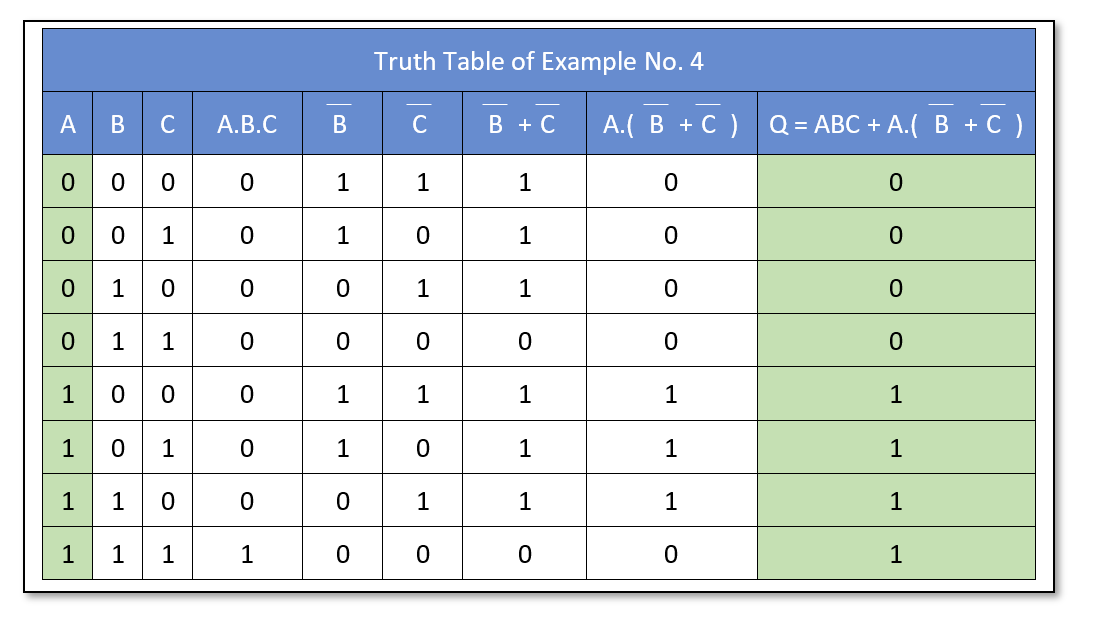
Using the digital logic circuit, Boolean expression at each stage has been derived and a truth table has been constructed using these Boolean expressions against each possible combination of input. The final output “Q” of the logic circuit has been analyzed which is equivalent to input “A”. A single wire from input “A” to output “Q” or a Buffer can replace this six-gate logic circuit. The truth table constructed has been shown below:
The Boolean expression of the given logic circuit has also been reduced below using Boolean algebra laws and theorems.
The above solution also reveals that the given logic circuit simplifies to have only a Buffer with input “A”. The reduced logic circuit has been shown below.
Figure 8: Solution of Example No. 4
The above examples show the ways to obtain a cost-effective, compact, and power-efficient solution. Similar, advantages can be obtained by adapting the same techniques to other digital logic circuits.
Conclusion
The complex digital circuit may be reduced to the simple logic circuit using Boolean Algebra Laws and Theorems.
The digital circuits with few inputs can be reduced by constructing the table and identifying the output with equivalent single gate logic or input.
PinePhone Pro Explorer Edition was initially announced on October 15, 2021, featuring the low-power and high-performance Rockchip RK3399S system-on-chip. As we all know, Rockchip has been releasing powerful SoCs in the market for embedded electronic hardware devices, but this chip is specifically designed for computing, personal mobile, and other smart devices. Taking advantage of Big.Little architecture and a NEON coprocessor, PinePhone Pro Explorer Edition is one of the very few Linux-based smartphones on the market.
As mentioned, the flagship smartphone is built around the RK3399S system-on-chip with tightly integrated 64-bit dual-core Arm Cortex-A72 and quad-core Arm Cortex-A53 processor clocked at up to 1.5GHz frequency. The hardware incorporates 4GB LPDDR4 SRAM operating at 800MHz frequency, which is decently good for a Linux-based handheld smart device. However, this smartphone cannot be compared among the other flagships and top-tier devices in the market.
Specifications of PinePhone Pro Explorer Edition
System: Rockchip RK3399S featuring 64-bit 6-core 4x ARM Cortex A53 and 2x ARM Cortex A72
GPU: Mali T860MP4
Storage: 128GB eMMC flash memory, Micro SD Card (supports SDHC and SDXC, up to 2TB)
Memory: 4GB LPDDR4 RAM
SIM card slot: Micro-SIM
Display:
Size: 6-inches diagonal
Type: 1440 x 720 in-cell IPS with Gorilla Glass 4
Resolution: 1440×720, 18:9 ratio
Camera:
Back Camera: 13MP Sony IMX258 with Gorilla Glass 4 protective layer and LED flash
Front Camera: 8MP, OmniVision OV8858 front-facing camera
Audio system: 3.5mm jack & mic and Loudspeaker
Battery: Lithium-ion, rated capacity 2800mAh
I/O: USB Type-C, USB Host, DisplayPort Alternate Mode output
Charging: Charging: USB type-C, 15W – 5V 3A Quick Charge, follows USB PD specifications
Operating system: Manjaro with Plasma Mobile
Dimension: 160.8×76.6×11.1 mm
Weight: Approx. 220g
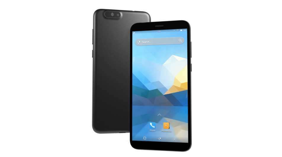
[Image Credit: CNX-Software]The back camera on the PinePhone Pro Explorer Edition comes with a 13MP Sony IMX258 with Gorilla Glass 4 protective layer along with a LED flashlight. When it comes to the front camera, the hardware features an 8MP OmniVision OV8858 front-facing camera for best-in-class performance. For the audio system, the smartphone provides a 3.5mm jack, mic, and a loudspeaker.
This 6-inch phone offers 1440×720 pixel resolution at an aspect ratio of 18:9. The internal storage for the PinePhone Pro Explorer Edition is 128GB eMMC while it can be expanded up to 2TB via MicroSD card. Such high internal storage is rare for most of the flagship smartphones on the market. On the side of the sensors, the hardware offers an accelerometer, gyroscope, proximity, ambient light, and compass sensors. While the battery life is one of the most concerning factors for the user, the device comes with a Lithium-ion rated capacity of 2800mAh.
All the orders placed before January 18, 2022, will be shipping starting on January 24, 2022, from the Hong Kong warehouse. While any orders placed after that date can be expected to ship as late as the end of February 2022. The PinePhone Pro Explorer Edition is currently priced at$399 on the official store.
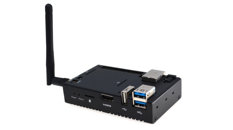
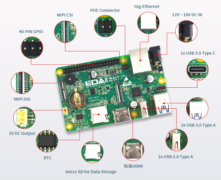
Raspberry Pi Compute Module 4 has been one of the most popular hardware from the manufacturer with its ever-increasing carrier boards. Chinese embedded electronic device manufacturer Edatech has released a new industrial box, CM4 Nano, built around the Raspberry Pi Compute Module 4 featuring compatibility with the Raspberry Pi 4B for industrial automation applications.
The onboard Raspberry Pi CM4 comes with a highly integrated Broadcom BCM2711 processor embedded with a 64-bit quad-core Arm Cortex-A72 clocked up to a frequency of 1.5GHz. With the advanced wireless connectivity through 2.4GHz and 5.0GHz IEEE 802.11b/g/n/ac, Bluetooth 5.0, and Bluetooth Low-Energy. The Raspberry Pi CM4 industrial computer comes with up to 8GB of LPDDR4 RAM and a capacity of up to 32GB of eMMC storage. The flash memory can be expanded through a micro–SD card slot.
Specifications of the CM4 Nano Industrial Computer
Module: Raspberry Pi Compute Module 4 with a quad-core Arm Cortex-A72 @1.5GHz
Memory: LPDDR4, up to 3200MT/s with options: 1GB, 2GB, 4GB, and 8GB
Storage: 8GB, 16GB and 32GB eMMC, expandable through microSD card
Wireless connectivity: 2.4G/5.0GHz Wi-Fi and Bluetooth LE 5.0
Power: 12V to 18V DC
Ethernet: 10/100/1000M, could support POE
USB ports: 3x USB3.0 and 1x USB2.0
HDMI ports: 1x HDMI A, 1x HDMI, 1x USB touch
Camera connector: 1x CSI
Display connector: 1x DSI
LED: Green (System Status) and Red (Power indicator)
Enclosure: Full metal case with a whole side aluminum alloy heat sink
Software support: Compatible with Raspberry Pi OS
Operating temperature: -25 to 50°C
Dimensions: 95x58x24 mm
Surprisingly, CM4 Nano is compared alongside Raspberry Pi 4B due to its customized capabilities to support several high-end applications. Onboard micro-SD card cannot be used to boot Raspberry Pi CM4 Nano Industrial Computer. Additionally, this interface takes the GPIO22 to GPIO27 out of the standard 40-pin interface. One interesting addition to the hardware is the support for PoE HAT which makes it easy and simple by combining both power and ethernet cables into one.
Raspberry Pi CM4 Nano Industrial Computer is available for purchase at AliExpress, starting at $113 for 1GB LPDDR4 RAM/ 8GB eMMC storage and going up to $210 for 8GB RAM/8GB storage.