Introducing Inforce 68A1, a powerful new system-on-module designed to enable advanced IoT vision system devices

SMART Wireless Computing, Inc., an SGH company and leading provider of edge computing embedded solutions, today announced the Inforce 68A1 system-on-module (SoM), a powerful new tool based on one of the latest and most advanced IoT solutions from Qualcomm Technologies, Inc., the Qualcomm® QCS8250 system-on-chip (SoC), which is designed to provide high performance for compute-intensive network edge Internet of Things (IoT) camera applications. The Inforce 68A1 SoM combines support for multiple high-resolution 8K or 4K cameras with complex artificial intelligence (AI) inferencing at the edge to enable smart camera systems, high-performance conferencing/collaboration devices, connected healthcare, and intelligent retail devices.

The Inforce 68A1 SoM provides exceptionally high-resolution video capabilities, including processing 4K60 Ultra HD content for multiple cameras and displays concurrently, plus high bandwidth connectivity via 802.11ax DBS Wi-Fi 6E and Bluetooth 5 for connected camera networks. The module makes use of Qualcomm Technologies’ high-performance Qualcomm® Hexagon DSP and Qualcomm® AI Engine to efficiently run heterogeneous deep learning workloads and neural networks for high-performance, on-device AI inferencing used in video analytics and to improve the user experience.

Video Conferencing Use Case

Never before has reliable video conferencing been more in demand, with companies across the globe embracing AI technology to simplify audio-visual collaboration as remote working becomes more widely adopted. By integrating the Inforce 68A1 SoM into enterprise video conferencing solutions, businesses can deliver content, connect and interact effortlessly, from anywhere, for a flawless video experience.

Medical Use Case

Similarly, applying computer vision AI to medical fields, such as portable ultrasound machines, can help provide remote anatomical identification with fewer clicks and increased accuracy. This anatomical identification also helps automate measurements, make them more reproducible, and can give medical professionals tools to improve patient care, and bolster the resources of hospitals that lack adequate medical imaging resources.

Retail Use Case

As retailers look to keep up with changing landscapes, the introduction of AI video content analysis solutions presents an entirely new level of data processing which leads to a deeper understanding of consumer attitudes, preferences, and buying habits. By integrating the Inforce 68A1 SoM into retail camera systems and self-checkout technology, retailers can improve merchandising and enhance customer behavior and engagement while providing a seamless, low-contact shopping experience.

“With vast progress being made in AI and machine learning, applications that previously involved manual intervention can now be automated or enhanced to solve some of the most common challenges in our day-to-day lives,” said Todd Wynia, vice president, product marketing at SMART Wireless Computing. “Our application-ready embedded platforms are at the core of this, providing multiple options for global IoT connectivity, multimedia capabilities, and powerful edge computing power, revolutionizing the way we communicate, shop and approach healthcare, among many other possible applications.”

“The Qualcomm QCS8250 SoC targets high performance, on-device camera applications in retail video analytics, connected healthcare, digital signage and enterprise video collaboration,” said Siddhartha Franco, director, business development, Qualcomm Technologies, Inc. “This device is optimized for maximum performance while balancing power efficiency with support for Wi-Fi 6 and 5G connectivity. The SMART Wireless Inforce 68A1 SoM brings technology at the connected intelligent edge to a broader ecosystem of developers, helping reduce the time and risks involved with integrating premium tier AI performance into their edge camera solutions.”

This latest module includes an Android 10 board support package with the Qualcomm Technologies’ software development kits, including Hexagon SDK and Qualcomm® Neural Processing Engine SDK, enabled.

Technical Specifications and Application Benefits

  • The Qualcomm QCS8250 SoC at the heart of the Inforce 68A1 SoM integrates:
    • The Qualcomm® Kryo 585 CPU is one of the company’s most advanced processors for IoT applications that provides excellent performance and multi-tasking.
    • The Qualcomm® Adreno 650 GPU provides a highly efficient graphics core, delivering twice the performance of the previous generation platform, and 60 percent greater power efficiency.
    • The Hexagon 690 DSP runs power efficient machine learning with quad-threaded Scalar performance and twice the Vector eXtensions performance
    • A dedicated computer vision hardware block and new Hexagon Tensor Accelerator delivering 15 TOPS of AI performance
    • The Qualcomm® Spectra 480 ISP enables image capture at 64MP@30fps ZSL with no shutter lag and quick autofocus.
    • The Adreno DPU995 Display Engine enables dual concurrent display content at HEVC 10bit and VP9 decode.
    • Wired and wireless connectivity options include Wi-Fi 6, 5G, Bluetooth 5.1 RF front-end technologies and dual USB 3.1.
    • A secure processing unit enables secure boot, DRM and content protection creating a secure environment for the camera system.
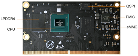
  • The Inforce 68A1 SoM leverages PMIC regulators for large power requirements and on-board power management.
  • On-board memory and storage includes 8GB DDR5 RAM and 64GB Universal Flash Storage (UFS) for fast multitasking.
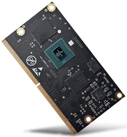
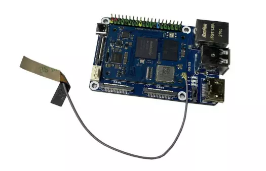
  • Designed to fit into and power ultra-thin applications, the small form factor SoM measures just 35 mm x 53 mm (7.5 mm profile).
  • Electromagnetic interference (EMI) shielding provides radio frequency noise protection, while also improving heat dissipation to improve performance.
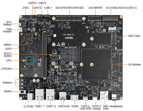
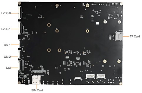
  • A development kit based on this SoM offers functionality to help developers create and optimize their products quickly, cost effectively and with lower risk.

Starting in December, customer samples will be available to order at www.smartwirelesscompute.com priced at $399 for the SoM and $749 for the development kit, which includes a SoM, evaluation carrier board with IO, and a starter kit that includes a power adapter and cable.

Weller’s Zero Smog 6V Fume Extraction System connects up to 8 workbenches

Weller Tools, the world’s No.1 brand in hand soldering solutions, is pleased to announce that its Zero Smog 6V Fume Extraction System can connect up to eight soldering workbenches.

The Zero Smog 6V (ZS 6V) Fume Extraction System is user-friendly with quick and simple installation and filter exchange. It has a low noise emission level and is small and convenient to locate within the work area. The high-quality components used in the ZS 6V result in low servicing requirements and long system life.

To increase filter lifetime and save on energy, the ZS 6V is fitted with constant flow control (CFC) – depending on the number of connected workplaces. To extend the capacity an external pre-filter can be fixed directly to the ZS 6V.

One of Weller’s largest extraction units, the ZS 6V features a powerful 615m3/hr (362 CFM) flowrate. The system’s large filter contains up to 13kg (29lbs) of granulated filtration media for an exceptionally long filter life.

more information: https://www.weller-tools.com/professional/EUR/en/Filtration/3D+printer+vapours/Zero+Smog+6V+fuer+Kleberdaempfe

MYIR Launched i.MX 8M Plus SoM with AI/ML Capabilities

After the former release of NXP i.MX 8M based MYC-JX8MX and i.MX 8M Mini based MYC-C8MMX System-on-Modules, MYIR has launched another advanced SoM MYC-JX8MPQ based on quad Arm Cortex-A53/M7 i.MX 8M Plus processor which is NXP’s first i.MX processor with a built-in 2.3 TOPS Neural Processing Unit (NPU) for extensive Artificial Intelligence (AI) and Machine Learning (ML) capabilities. The i.MX 8M Plus also has integrated 1080p Video Processing Unit (VPU), 2D/3D Graphics Processing Unit (GPU), dual ISPs (Image Signal Processors) and audio DSP to provide a perfect solution for machine learning and vision, advanced multimedia, and industrial automation applications.

MYC-JX8MPQ CPU Module

Measuring 82mm by 45mm, the MYC-JX8MPQ CPU Module takes full features of the i.MX 8M Plus processor and carries out most of the I/O signals to and from the CPU Module through a 0.5mm pitch 314-pin MXM 3.0 gold-finger-edge-card connector. It has 3GB LPDDR4, 8GB eMMC and 32MB QSPI flash default memory and storage configuration as well as integrated PMIC. It is capable of running Linux OS and provided with plenty of software resources and demos.

MYD-JX8MPQ Development Board Top-view (delivered with installed heatsink by default)

MYIR offers MYD-JX8MPQ Development Board for evaluating the MYC-JX8MPQ CPU Module, which is a complete evaluation platform with rich peripheral set and connectivity including UARTs, USB 3.0 Host, OTG, dual Gigabit Ethernet, dual CAN, dual M.2 Sockets (one for 5G LTE Module and one for PCIe SSD), one extension header for connecting with MYIR’s MY-WF005S WiFi/Bluetooth module and one UART/I2C/SPI/GPIO extension header which is compatible with Raspberry Pi interface, Micro SD card slot, dual MIPI-CSI Camera Interfaces, LVDS /MIPI-DSI display interface, Audio, HDMI, etc. MYIR can also offer design services to help customize the base board according to customers’ requirements.

MYIR offers commercial and industrial options for CPU Modules and Development boards. The prices are economic. Discount is to be offered for volume quantities.

Product Item Part No. Retail Price
MYC-JX8MPQ CPU Module MYC-JX8MPQ-8E3D-160-C $115/pc
MYC-JX8MPQ-8E3D-160-I $129/pc
MYD-JX8MPQ Development Board MYD-JX8MPQ-8E3D-160-C $335/pc
MYD-JX8MPQ-8E3D-160-I $349/pc

More information about above new products can be found at:

Analog Devices Inc. MAX31888 Digital Temperature Sensor

Analog Devices Inc. MAX31888 Digital Temperature Sensor is a 1-Wire high precision, low power digital temperature sensor. The sensor has ±0.25ºC accuracy from -20ºC to +105ºC for precision temperature monitoring. The MAX31888 operates at 68μA operating current during measurement and has a 16-bit resolution (0.005ºC).

Features

  • High accuracy and precision
    • ±0.25ºC accuracy from -20ºC to +105ºC
    • ±0.65ºC accuracy from -40ºC to +125ºC
  • Long battery life
    • 1.7V to 3.6V operating voltage
    • 68µA operating current during the measurement
    • 0.6µA standby current
  • Small size
    • 2mm x 2mm x 0.8mm, 6-Pin μDFN
  • Safety and compliance
    • Unique ROM IDs allow the device to be NIST traceable
    • High and low-temperature alarms
  • Simple and robust digital interface
    • 1-Wire® interface
    • CRC (Cyclic Redundancy Check)
    • Multi-drop capability

more information: https://www.maximintegrated.com/en/products/sensors/MAX31888.html

Toshiba 2SA/2SC Bipolar Transistors

Toshiba 2SA/2SC Bipolar Transistors are AEC-Q101 qualified and designed for low-frequency, AM, and audio frequency general purpose amplifier applications. The 2SA/2SC Transistors feature high voltage, high collector current, high hFE, and excellent hFE linearity. The Toshiba 2SA/2SC Bipolar Transistors are available in a small SSM, USM, or S-Mini package.

Features

  • AEC-Q101 qualified
  • High voltage
  • High collector current
  • High hFE
  • Excellent hFE linearity
  • Small SSM, USM, or S-Mini packages

Pinout

more information: https://gr.mouser.com/c/?marcom=199670766

Vishay VEML3235 Ambient Light Sensors

Vishay VEML3235 Ambient Light Sensors are advanced low power, high sensitivity sensors with I²C protocol interface and are designed by the CMOS process. These sensors houses photodiode, amplifiers, and analog circuits in a single chip and are easy to operate using simple I²C commands. The better spectral sensitivity is used to closely capture real human eye responses. The VEML3235/VEML3235SL feature excellent temperature compensation and a robust refresh rate setting that does not require an external RC low pass filter. Additionally, these ambient light sensors offer high dynamic detection resolution and software shutdown mode control as well. Typical applications include handheld devices, notebooks, consumer devices, industrial and medical applications, computing, and industrial devices and displays.

Features

  • Surface-mount package type
  • Integrated modules:
    • Ambient Light Sensor (ALS)
  • 2.6V to 3.6V supply voltage range VDD
  • Communication via I²C interface
  • 1.7V to 3.6V I²C bus H-level range
  • Floor life:
    • 168h, MSL 3, according to J-STD-020
  • 1μA low stand-by current consumption (typical)
  • Dimensions (L x W x H):
    • VEML3235: 2mm x 2mm x 0.87mm
    • VEML3235SL: 2.95mm x 1.5mm x 1.5mm

more information: https://www.vishay.com/optical-sensors/list/product-80131/

New 13.56MHz Wireless Power Supply Chipset for Wearable Devices and Industrial Equipment

ROHM Group company LAPIS Technology has developed a new chipset that utilizes the 13.56MHz frequency band for both wireless power supply and Near Field Communication (NFC) and contributes to improved design flexibility in devices with rotating mechanisms that would be restricted by wired designs, such as industrial equipment, PC cooling fans, and e-bike torque sensors. This chipset is capable of providing up to 1W of wireless power for compact and streamlined wearable devices, and for industrial smart, miniaturized, and sealed solutions.

The new ML7661 (transmitter) and ML7660 (receiver) eliminate the need for an external MCU by incorporating a control circuit required for transmission/reception which makes it ideal for wearables with a large battery capacity designed to be worn for long time frames. This chipset features an in-built communication protocol that supports both I2C and SPI interfaces, enabling control of digital sensors and other devices without an MCU.

Key Features

  • Delivers up to 1W of power in the industry’s smallest system size
  • Enabling both wireless power supply and communication contributes to improved application design flexibility
  • MCU-less system configuration reduces development load

In addition, this chipset facilitates system configuration by adjusting power transmission to increase power supply efficiency and setting parameters such as temperature thresholds according to the specifications of the rechargeable battery which eliminates the need for a system control MCU along with the requisite program development, reducing development load considerably.

more information:

ESP32-based SparkFun Thing Plus SkeleBoard For A Wide Range of Applications

SparkFun Thing Plus SkeleBoard

Due to the expanded capabilities offered by every ESP32 processor coming to market, many designers and manufacturers realize the importance to unveil ESP32-based development boards in various form factors. Recently, SparkFun released a limited edition of the Thing Plus SkeleBoard based on the ESP32 WROOM (U.FL) that targets a wide range of applications ranging from low-power sensor networks to voice encoding and music streaming.

The motivation behind designing this board enables developers to get started with Espressif IoT ideations through a powerful yet generic onboard system-on-chip. The ESP32 WROOM features the Xtensa dual-core 32-bit LX6 microprocessor with a decent wireless connective through Wi-Fi, Bluetooth, and BLE modules. The processor is clocked at up to a frequency of up to 240 MHz with 520kB internal SRAM. There also comes a small 16MB of flash storage to save programs for targeted applications.

At the heart of the onboard ESP32 WROOM SoC is the ESP32-D0WDQ6 chip module is embedded to be scalable and adaptive. Even though there are two CPU cores, both can be manually controlled and the CPU clock frequency is adjustable from 80 MHz to 240 MHz. With the low-power mode, the developer can power off the CPU and allow the co-processor to monitor the interfacing peripherals. Let us take a detailed look at the specifications of the SparkFun Thing Plus Skeleboard.

Specifications of SparkFun Thing Plus SkeleBoard:

  • SoC: ESP32 WROOM featuring Xtensa® dual-core 32-bit LX6 microprocessor at up to 240 MHz clock frequency.
  • Memory: 520kB internal SRAM
  • Storage: 16MB of flash storage expandable with SD card interface
  • Wireless Connectivity: Wi-Fi+BT+BLE
  • Interfaces: Ethernet, high-speed SPI, UART, I2S and I2C
  • Connector: JST connector (LiPo battery) and a U.FL connector
  • GPIOs: 21 GPIO
  • Power: 2.3 to 3.6V operating range
  • Dimension: 2.30 x 0.90 Inches

The board supports the SparkFun Qwiic Connect System, which is an ecosystem of I2C sensors, actuators, shields and cables for faster prototyping and reducing the time to market. Also, with the JST connector, the operator can plug in a LiPo battery for remote applications. SparkFun Thing Plus Skeleboard also features 8-electrode capacitive touch for touch sensors.

If you are interested in getting more details on the board, head to the official product page.

Pine64 Releases Three Hostboards For Their SOQuartz Module

Pine64 recently released SOQuartz as its latest member of the Quartz products in June this year, and now the community-driven hardware company has released host boards to make SOQuartz interesting for development.

The SOQuartz like Quartz364 is a computer built based on the Rockchip RK3566 SoC with quad-core, ARM Cortex-A55 processor featuring a Mali-G52 2EE GPU. The SOQuartz features the RAM configuration with Quartz64 apart from being software compatible. The module also debuts an inbuilt eMMC flash storage through an eMMC socket or solder interface, an Azurewave AW-CM256SM Wi-Fi 802.11ac Bluetooth/Wi-Fi module, and 100-pin connectors on its PCB back. SOQuartz pin-out is compatible with Raspberry Pi CM4, so it can work as a replacement with existing CM4 baseboards (hostboards).

The recently released SOQuartz host boards, on the other hand, include a Model-A type which is specifically a development board; a small form-factor type with dual cameras, HDMI, Gbe, and 2x USB 2.0 header; and a Blade host board with Gigabit Ethernet interface, micro SD card slot, 1x USB2.0 header, 40 GPIO header, and a UART output. With the Blade host board compatibility with the server rack, many of it can be housed in any 1U standard rack. And that is already a big plus if you ask me since it will support a cluster of computable project development, that is versatility. The three boards are not the last Quartz-line boards according to the November update by Lukasz Erecinski of Pine64. Key features and specifications of the three (3) host boards are given below.

Specifications of the Model-A host board:

  • Compatibility with SOQuartz SoM
  • MicroSD card
  • 12V/3A power supply via DC jack or 4-pin header
  • HDMI 2.0 up to 4Kp60
  • 2x MIPI DSI connectors (2-lane + 4-lane)
  • 1x eDP connector
  • 2x MIPI CSI connectors (2-lane + 4-lane)
  • Gigabit Ethernet
  • 2x USB 2.0 interfaces
  • 2x USB 3.0 interfaces
  • Colour-coded 40-pin GPIO header
  • PCIe 1x open-ended slot
  • Fan header
  • Dimensions: 133 mm x 80 mm

Specifications of the Small Form-factor host board:

  • Compatibility with SOQuartz SoM with quad-core Cortex-A55 processor with 2GB to 8GB RAM, optional eMMC flash (up to 128GB) + optional Wi-Fi 5 + Bluetooth 5.0 module
  • 5V power supply via USB-C port or 4-pin header
  • HDMI 2.0 up to 4Kp60
  • 1x MIPI DSI connector
  • 2x MIPI CSI connectors
  • Gigabit Ethernet
  • 2x USB 2.0 ports
  • 1x USB-C port (power supply)
  • Color-coded 40-pin GPIO header
  • Dimensions: 85 mm x 56 mm (about)

Specifications of the Blade host board:

  • Compatible with SOQuartz SoM
  • M.2 PCIe slot for NVMe SSD (supports 4 dimensions) + MicroSD card slot
  • HDMI 2.0 (up to 4Kp60)
  • Gigabit Ethernet RJ45 port
  • 1x vertical USB 2.0 port
  • 1x USB header
  • 40-pin GPIO header
  • Debugging: 3.5 mm jack (UART debugging)

As of this writing, none of the three SOQuartz boards is available for purchase but further information on them can be found on the Pine64 Wiki (although not sufficient at the moment) and Pine64 blog.

You should eventually be informed of the availability of host boards and updates.

Make a BLE enabled Smart Bulb with STM32 and BleuIO

Home automation involves automating household environment equipment. To achieve that, we have created a smart bulb that is easy to install, and the attached equipment can be controlled over a web browser or smartphone app. The aim of this project is to control different home appliances using a web browser or smartphone.

1. Introduction

The project is showcasing a simple way of using the the BleuIO Dongle to turn on and off a light bulb that is connected to the STM32 Nucleo-144 via a 5V Relay.

You will need two dongles, one connected to the Nucleo board and one connected to a computer, running the web script.
When the BleuIO Dongle is connected to the Nucleo boards USB port the STM32 will recognize it and directly start advertising. This allows the other Dongle to connect to it.

It will also accept 3 different inputs from the UART:

input result
0 Send ATI (Request device information) command to BlueIO Dongle.
1 Manually turn the light bulb on
2 Manually turn the light bulb off

We have used an STM32 Nucleo-144 development board with STM32H743ZI MCU (STM32H743ZI micro mbed-Enabled Development Nucleo-144 series ARM® Cortex®-M7 MCU 32-Bit Embedded Evaluation Board) for this example.

If you want to use another setup you will have to make sure it supports USB Host and beware that the GPIO setup might be different and may need to be reconfigured in the .ioc file.

WARNING – THIS PROJECT INVOLVES HIGH VOLTAGES THAT CAN CAUSE SERIOUS INJURY OR DEATH. PLEASE TAKE ALL NECESSARY PRECAUTIONS, AND TURN OFF ALL POWER TO A CIRCUIT BEFORE WORKING ON IT.

2. Connecting the relay

Beware:

Always be very careful when experimenting with AC, electrical shock can result in serious injuries! NOTICE OF RISK; DISCLAIMER OF LIABILITY

Pinout and Connection to STM32 For the DC part of the Relay circuit connect S (signal) to pin PE4 on the STM32 NUCLEO board, also connect the Power supply (+) and ground (-) to +5V and GND respectively.

3. About the Code

You can get the project HERE

https://github.com/smart-sensor-devices-ab/stm32_bleuio_lightbulb_example

This project-based on our previous STM32 project (https://github.com/smart-sensor-devices-ab/stm32_bleuio_example) with these changes in the .ioc file:

In the pinout view, we set the GPIO PE4 to OUTPUT and labeled it to ‘lightbulb’.

In the USBH_CDC_ReceiveCallback function in USB_HOST\usb_host.c we copy the CDC_RX_Buffer into an external variable called dongle_response that is accessible from the main.c file.

void USBH_CDC_ReceiveCallback(USBH_HandleTypeDef *phost)
{
    if(phost == &hUsbHostFS)
    {
        // Handles the data recived from the USB CDC host, here just printing it out to UART
        rx_size = USBH_CDC_GetLastReceivedDataSize(phost);
        HAL_UART_Transmit(&huart3, CDC_RX_Buffer, rx_size, HAL_MAX_DELAY);

        // Copy buffer to external dongle_response buffer
        strcpy((char *)dongle_response, (char *)CDC_RX_Buffer);

        memset(CDC_RX_Buffer,0,RX_BUFF_SIZE);
        USBH_CDC_Receive(phost, CDC_RX_Buffer, RX_BUFF_SIZE);
    }

    return;
}

In main.c we create a simple interpreter so we can react to the data we are receiving from the dongle.

/**
  * @brief Simple dongle interpreter
  * @retval None
  */
void dongle_interpreter(uint8_t * input)
{

    if(strlen((char *)input) != 0)
    {
        if(strstr((char *)input, "\r\nADVERTISING...") != NULL)
        {
            isAdvertising = true;
        }
        if(strstr((char *)input, "\r\nADVERTISING STOPPED.") != NULL)
        {
            isAdvertising = false;
        }
        if(strstr((char *)input, "\r\nCONNECTED") != NULL)
        {
            isConnected = true;
            HAL_GPIO_WritePin(GPIOE, GPIO_PIN_1, GPIO_PIN_SET);
        }
        if(strstr((char *)input, "\r\nDISCONNECTED") != NULL)
        {
            isConnected = false;
            HAL_GPIO_WritePin(GPIOE, GPIO_PIN_1, GPIO_PIN_RESET);
        }
        if(strstr((char *)input, "L=0") != NULL)
        {
            isLightBulbOn = false;
            HAL_GPIO_WritePin(Lightbulb_GPIO_Port, Lightbulb_Pin, GPIO_PIN_RESET);

            writeToDongle((uint8_t*)DONGLE_SEND_LIGHT_OFF);

            uart_buf_len = sprintf(uart_tx_buf, "\r\nLight bulb is %s\r\n", isLightBulbOn ? "on":"off");
            HAL_UART_Transmit(&huart3, (uint8_t *)uart_tx_buf, uart_buf_len, HAL_MAX_DELAY);
        }
        if(strstr((char *)input, "L=1") != NULL)
        {
            isLightBulbOn = true;
            HAL_GPIO_WritePin(Lightbulb_GPIO_Port, Lightbulb_Pin, GPIO_PIN_SET);

            writeToDongle((uint8_t*)DONGLE_SEND_LIGHT_ON);

            uart_buf_len = sprintf(uart_tx_buf, "\r\nLight bulb is %s\r\n", isLightBulbOn ? "on":"off");
            HAL_UART_Transmit(&huart3, (uint8_t *)uart_tx_buf, uart_buf_len, HAL_MAX_DELAY);
        }
    }
    memset(&dongle_response, 0, RSP_SIZE);
}

We also update the handleUartInput function so we can have manual control over the light bulb via the UART.

/**
  * @brief Simple uart input handler
  * @retval None
  */
void handleUartInput(UARTCommandTypeDef cmd)
{
    switch(cmd)
    {
        case UART_RX_0:
        {
            // 0
            uart_buf_len = sprintf(uart_tx_buf, "\r\n(0 pressed)\r\n");
            HAL_UART_Transmit(&huart3, (uint8_t *)uart_tx_buf, uart_buf_len, HAL_MAX_DELAY);
            if(isBleuIOReady)
            {
                writeToDongle((uint8_t*)DONGLE_CMD_ATI);
            } else
            {
                uart_buf_len = sprintf(uart_tx_buf, BLEUIO_NOT_READY_MSG);
                HAL_UART_Transmit(&huart3, (uint8_t *)uart_tx_buf, uart_buf_len, HAL_MAX_DELAY);
            }
            uartStatus = UART_RX_NONE;
            break;
        }
        case UART_RX_1:
        {
            // 1
            uart_buf_len = sprintf(uart_tx_buf, "\r\n(1 pressed light bulb on!)\r\n");
            HAL_UART_Transmit(&huart3, (uint8_t *)uart_tx_buf, uart_buf_len, HAL_MAX_DELAY);
            HAL_GPIO_WritePin(Lightbulb_GPIO_Port, Lightbulb_Pin, GPIO_PIN_SET);
            uartStatus = UART_RX_NONE;
            break;
        }
        case UART_RX_2:
        {
            // 2
            uart_buf_len = sprintf(uart_tx_buf, "\r\n(2 pressed light bulb off!)\r\n");
            HAL_UART_Transmit(&huart3, (uint8_t *)uart_tx_buf, uart_buf_len, HAL_MAX_DELAY);
            HAL_GPIO_WritePin(Lightbulb_GPIO_Port, Lightbulb_Pin, GPIO_PIN_RESET);

            uartStatus = UART_RX_NONE;
            break;
        }
        case UART_RX_NONE:
        {
            break;
        }
        default:
        {
            uartStatus = UART_RX_NONE;
            break;
        }
    }
}

We put the interpreter function inside the main loop.

/* Infinite loop */
  /* USER CODE BEGIN WHILE */
  while (1)
  {
    /* USER CODE END WHILE */
    MX_USB_HOST_Process();

    /* USER CODE BEGIN 3 */
    // Simple handler for uart input
    handleUartInput(uartStatus);
    // Inteprets the dongle data
    dongle_interpreter(dongle_response);

    // Starts advertising as soon as the Dongle is ready.
    if(!isAdvertising && !isConnected && isBleuIOReady)
    {
        HAL_Delay(200);
        writeToDongle((uint8_t*)DONGLE_CMD_AT_ADVSTART);
        isAdvertising = true;
    }
  }
  /* USER CODE END 3 */

4. Using the example project

4.1 What you will need

  • Two BleuIO dongles (https://www.bleuio.com)
  • The script for the dongle (available on the source code inside the web script folder)

A board with an STM32 Microcontroller with a USB port. (A Nucleo-144 development board: NUCLEO-H743ZI2, was used to develop this example. (https://www.st.com/en/evaluation-tools/nucleo-h743zi.html)

To connect the dongle to the Nucleo board a “USB A to Micro USB B”-cable with a USB A female-to-female adapter can be used.

5. How to setup project

5.1 Downloading the project from GitHub

Get project HERE

https://github.com/smart-sensor-devices-ab/stm32_bleuio_lightbulb_example

Either clone the project, or download it as a zip file and unzip it, into your STM32CubeIDE workspace.

5.2 Importing as an Existing Project

From STM32CubeIDE choose File>Import…

Then choose General>Existing Projects into Workspace then click ‘Next >’

  • Make sure you’ve chosen your workspace in ‘Select root directory:’
  • You should see the project “stm32_bleuio_example”, check it, and click ‘Finish’.

6. Running the example

  • In STMCubeIDE click the hammer icon to build the project.
  • Open up the ‘STMicroelectronics STLink Virtual COM Port’ with a serial terminal emulation program like TeraTerm, Putty or CoolTerm.Serial port Setup:
    Baudrate: 115200
    Data Bits: 8
    Parity: None
    Stop Bits: 1
    Flow Control: None
  • Connect the BleuIO Dongle before running the example.
  • In STMCubeIDE click the green play button to flash and run it on your board. The first time you click it the ‘Run Configuration’ window will appear. You can just leave it as is and click run.
  • You should be greeted by this welcome message:
  • Wait until the message: “[BleuIO Dongle Ready]” is shown.
  • You can now connect with the other dongle using the script.

You can also use the UART commands (0, 1 or 2):

  • Press 0 to get device information.1 to turn on the lightbulb.2 to turn off the lightbulb.

    Dongle response will be printed to UART.

7. Controlling the light from a web browser

We wrote a simple script that connects to the dongle and sends signals to toggle the light from the web browser.

For this script to work, we need

Steps

Create a simple Html file called index.html which will serve as the frontend of the script. This Html file contains some buttons that help connect and signal to the remote dongle, which is connected to stm32.

<!DOCTYPE html>
<html lang="en">
  <head>
    <meta charset="UTF-8" />
    <meta http-equiv="X-UA-Compatible" content="IE=edge" />
    <meta name="viewport" content="width=device-width, initial-scale=1.0" />
    <link
      href="https://cdn.jsdelivr.net/npm/[email protected]/dist/css/bootstrap.min.css"
      rel="stylesheet"
      integrity="sha384-1BmE4kWBq78iYhFldvKuhfTAU6auU8tT94WrHftjDbrCEXSU1oBoqyl2QvZ6jIW3"
      crossorigin="anonymous"
    />
    <title>Control Light using Bleutooth Low Energy</title>
  </head>
  <body class="mt-5">
    <div class="container mt-5">
      <h1 class="mb-5">Control Light using Bleutooth Low Energy</h1>
      <button class="btn btn-success" id="connect">Connect</button>
      <button class="btn btn-warning" id="lightOn" disabled>Turn On</button>
      <button class="btn btn-danger" id="lightOf" disabled>Turn Off</button>
    </div>
    <div class="container mt-5">
      <img id="light" src="light_off.png" alt="" />
    </div>

    <script src="script.js"></script>
  </body>
</html>

Create a js file called script.js and include it at the bottom of the Html file. This js file uses the BleuIO js library to write AT commands and communicate with the other dongle.

import * as my_dongle from "bleuio";
const dongleToConnect = "[0]40:48:FD:E5:35:A5";
import lightOnImg from "./light_on.png";
import lightOfImg from "./light_off.png";
document.getElementById("connect").addEventListener("click", function () {
  my_dongle.at_connect();
  document.getElementById("lightOn").disabled = false;
  document.getElementById("lightOf").disabled = false;
  document.getElementById("connect").disabled = true;
});

document.getElementById("lightOn").addEventListener("click", function () {
  my_dongle
    .ati()
    .then((data) => {
      //make central if not
      if (JSON.stringify(data).includes("Peripheral")) {
        console.log("peripheral");
        my_dongle.at_central().then((x) => {
          console.log("central now");
        });
      }
    })
    .then(() => {
      // connect to dongle
      my_dongle
        .at_getconn()
        .then((y) => {
          if (JSON.stringify(y).includes(dongleToConnect)) {
            console.log("already connected");
          } else {
            my_dongle.at_gapconnect(dongleToConnect).then(() => {
              console.log("connected successfully");
            });
          }
        })
        .then(() => {
          // send command to control light
          my_dongle.at_spssend("L=1").then(() => {
            console.log("Turned on");
            document.getElementById("light").src = lightOnImg;
          });
        });
    });
});

document.getElementById("lightOf").addEventListener("click", function () {
  my_dongle
    .ati()
    .then((data) => {
      //make central if not
      if (JSON.stringify(data).includes("Peripheral")) {
        console.log("peripheral");
        my_dongle.at_central().then((x) => {
          console.log("central now");
        });
      }
    })
    .then(() => {
      // connect to dongle
      my_dongle
        .at_getconn()
        .then((y) => {
          if (JSON.stringify(y).includes(dongleToConnect)) {
            console.log("already connected");
          } else {
            my_dongle.at_gapconnect(dongleToConnect).then(() => {
              console.log("connected successfully");
            });
          }
        })
        .then(() => {
          // send command to control light
          my_dongle.at_spssend("L=0").then(() => {
            console.log("Turned off");
            document.getElementById("light").src = lightOfImg;
          });
        });
    });
});

The script js file has three button actions; connect and control light.

Now we need to know the ID of the other dongle connected to STM32 so that we can connect to it. You can use this web terminal to get the dongle ID.

- Open this site https://bleuio.com/web_terminal.html and click connect to dongle.
- Select the appropriate port to connect.
- Once it says connected, type **"ATI"**. This will show dongle information and current status.
- If the dongle is on peripheral role, set it to central by typing **"AT+CENTRAL"**
- Now do a gap scan by typing **"AT+GAPSCAN"**
- Once you see your dongle on the list ,stop the scan by pressing control+c
- Copy the ID and paste it into the script (script.js) line #2

You will need a web bundler. You can use parcel.js

Once parcel js is installed, go to the root directory and type “parcel index.html”. This will start your development environment.

Open the script on a browser using parcel js.

You can easily connect to the dongle and turn on-off light from there.

TOP PCB Companies