Vishay VEML3235 Ambient Light Sensors

Vishay VEML3235 Ambient Light Sensors are advanced low power, high sensitivity sensors with I²C protocol interface and are designed by the CMOS process. These sensors houses photodiode, amplifiers, and analog circuits in a single chip and are easy to operate using simple I²C commands. The better spectral sensitivity is used to closely capture real human eye responses. The VEML3235/VEML3235SL feature excellent temperature compensation and a robust refresh rate setting that does not require an external RC low pass filter. Additionally, these ambient light sensors offer high dynamic detection resolution and software shutdown mode control as well. Typical applications include handheld devices, notebooks, consumer devices, industrial and medical applications, computing, and industrial devices and displays.

Features

  • Surface-mount package type
  • Integrated modules:
    • Ambient Light Sensor (ALS)
  • 2.6V to 3.6V supply voltage range VDD
  • Communication via I²C interface
  • 1.7V to 3.6V I²C bus H-level range
  • Floor life:
    • 168h, MSL 3, according to J-STD-020
  • 1μA low stand-by current consumption (typical)
  • Dimensions (L x W x H):
    • VEML3235: 2mm x 2mm x 0.87mm
    • VEML3235SL: 2.95mm x 1.5mm x 1.5mm

more information: https://www.vishay.com/optical-sensors/list/product-80131/

New 13.56MHz Wireless Power Supply Chipset for Wearable Devices and Industrial Equipment

ROHM Group company LAPIS Technology has developed a new chipset that utilizes the 13.56MHz frequency band for both wireless power supply and Near Field Communication (NFC) and contributes to improved design flexibility in devices with rotating mechanisms that would be restricted by wired designs, such as industrial equipment, PC cooling fans, and e-bike torque sensors. This chipset is capable of providing up to 1W of wireless power for compact and streamlined wearable devices, and for industrial smart, miniaturized, and sealed solutions.

The new ML7661 (transmitter) and ML7660 (receiver) eliminate the need for an external MCU by incorporating a control circuit required for transmission/reception which makes it ideal for wearables with a large battery capacity designed to be worn for long time frames. This chipset features an in-built communication protocol that supports both I2C and SPI interfaces, enabling control of digital sensors and other devices without an MCU.

Key Features

  • Delivers up to 1W of power in the industry’s smallest system size
  • Enabling both wireless power supply and communication contributes to improved application design flexibility
  • MCU-less system configuration reduces development load

In addition, this chipset facilitates system configuration by adjusting power transmission to increase power supply efficiency and setting parameters such as temperature thresholds according to the specifications of the rechargeable battery which eliminates the need for a system control MCU along with the requisite program development, reducing development load considerably.

more information:

ESP32-based SparkFun Thing Plus SkeleBoard For A Wide Range of Applications

SparkFun Thing Plus SkeleBoard

Due to the expanded capabilities offered by every ESP32 processor coming to market, many designers and manufacturers realize the importance to unveil ESP32-based development boards in various form factors. Recently, SparkFun released a limited edition of the Thing Plus SkeleBoard based on the ESP32 WROOM (U.FL) that targets a wide range of applications ranging from low-power sensor networks to voice encoding and music streaming.

The motivation behind designing this board enables developers to get started with Espressif IoT ideations through a powerful yet generic onboard system-on-chip. The ESP32 WROOM features the Xtensa dual-core 32-bit LX6 microprocessor with a decent wireless connective through Wi-Fi, Bluetooth, and BLE modules. The processor is clocked at up to a frequency of up to 240 MHz with 520kB internal SRAM. There also comes a small 16MB of flash storage to save programs for targeted applications.

At the heart of the onboard ESP32 WROOM SoC is the ESP32-D0WDQ6 chip module is embedded to be scalable and adaptive. Even though there are two CPU cores, both can be manually controlled and the CPU clock frequency is adjustable from 80 MHz to 240 MHz. With the low-power mode, the developer can power off the CPU and allow the co-processor to monitor the interfacing peripherals. Let us take a detailed look at the specifications of the SparkFun Thing Plus Skeleboard.

Specifications of SparkFun Thing Plus SkeleBoard:

  • SoC: ESP32 WROOM featuring Xtensa® dual-core 32-bit LX6 microprocessor at up to 240 MHz clock frequency.
  • Memory: 520kB internal SRAM
  • Storage: 16MB of flash storage expandable with SD card interface
  • Wireless Connectivity: Wi-Fi+BT+BLE
  • Interfaces: Ethernet, high-speed SPI, UART, I2S and I2C
  • Connector: JST connector (LiPo battery) and a U.FL connector
  • GPIOs: 21 GPIO
  • Power: 2.3 to 3.6V operating range
  • Dimension: 2.30 x 0.90 Inches

The board supports the SparkFun Qwiic Connect System, which is an ecosystem of I2C sensors, actuators, shields and cables for faster prototyping and reducing the time to market. Also, with the JST connector, the operator can plug in a LiPo battery for remote applications. SparkFun Thing Plus Skeleboard also features 8-electrode capacitive touch for touch sensors.

If you are interested in getting more details on the board, head to the official product page.

Pine64 Releases Three Hostboards For Their SOQuartz Module

Pine64 recently released SOQuartz as its latest member of the Quartz products in June this year, and now the community-driven hardware company has released host boards to make SOQuartz interesting for development.

The SOQuartz like Quartz364 is a computer built based on the Rockchip RK3566 SoC with quad-core, ARM Cortex-A55 processor featuring a Mali-G52 2EE GPU. The SOQuartz features the RAM configuration with Quartz64 apart from being software compatible. The module also debuts an inbuilt eMMC flash storage through an eMMC socket or solder interface, an Azurewave AW-CM256SM Wi-Fi 802.11ac Bluetooth/Wi-Fi module, and 100-pin connectors on its PCB back. SOQuartz pin-out is compatible with Raspberry Pi CM4, so it can work as a replacement with existing CM4 baseboards (hostboards).

The recently released SOQuartz host boards, on the other hand, include a Model-A type which is specifically a development board; a small form-factor type with dual cameras, HDMI, Gbe, and 2x USB 2.0 header; and a Blade host board with Gigabit Ethernet interface, micro SD card slot, 1x USB2.0 header, 40 GPIO header, and a UART output. With the Blade host board compatibility with the server rack, many of it can be housed in any 1U standard rack. And that is already a big plus if you ask me since it will support a cluster of computable project development, that is versatility. The three boards are not the last Quartz-line boards according to the November update by Lukasz Erecinski of Pine64. Key features and specifications of the three (3) host boards are given below.

Specifications of the Model-A host board:

  • Compatibility with SOQuartz SoM
  • MicroSD card
  • 12V/3A power supply via DC jack or 4-pin header
  • HDMI 2.0 up to 4Kp60
  • 2x MIPI DSI connectors (2-lane + 4-lane)
  • 1x eDP connector
  • 2x MIPI CSI connectors (2-lane + 4-lane)
  • Gigabit Ethernet
  • 2x USB 2.0 interfaces
  • 2x USB 3.0 interfaces
  • Colour-coded 40-pin GPIO header
  • PCIe 1x open-ended slot
  • Fan header
  • Dimensions: 133 mm x 80 mm

Specifications of the Small Form-factor host board:

  • Compatibility with SOQuartz SoM with quad-core Cortex-A55 processor with 2GB to 8GB RAM, optional eMMC flash (up to 128GB) + optional Wi-Fi 5 + Bluetooth 5.0 module
  • 5V power supply via USB-C port or 4-pin header
  • HDMI 2.0 up to 4Kp60
  • 1x MIPI DSI connector
  • 2x MIPI CSI connectors
  • Gigabit Ethernet
  • 2x USB 2.0 ports
  • 1x USB-C port (power supply)
  • Color-coded 40-pin GPIO header
  • Dimensions: 85 mm x 56 mm (about)

Specifications of the Blade host board:

  • Compatible with SOQuartz SoM
  • M.2 PCIe slot for NVMe SSD (supports 4 dimensions) + MicroSD card slot
  • HDMI 2.0 (up to 4Kp60)
  • Gigabit Ethernet RJ45 port
  • 1x vertical USB 2.0 port
  • 1x USB header
  • 40-pin GPIO header
  • Debugging: 3.5 mm jack (UART debugging)

As of this writing, none of the three SOQuartz boards is available for purchase but further information on them can be found on the Pine64 Wiki (although not sufficient at the moment) and Pine64 blog.

You should eventually be informed of the availability of host boards and updates.

Make a BLE enabled Smart Bulb with STM32 and BleuIO

Home automation involves automating household environment equipment. To achieve that, we have created a smart bulb that is easy to install, and the attached equipment can be controlled over a web browser or smartphone app. The aim of this project is to control different home appliances using a web browser or smartphone.

1. Introduction

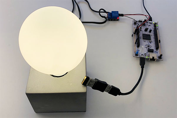
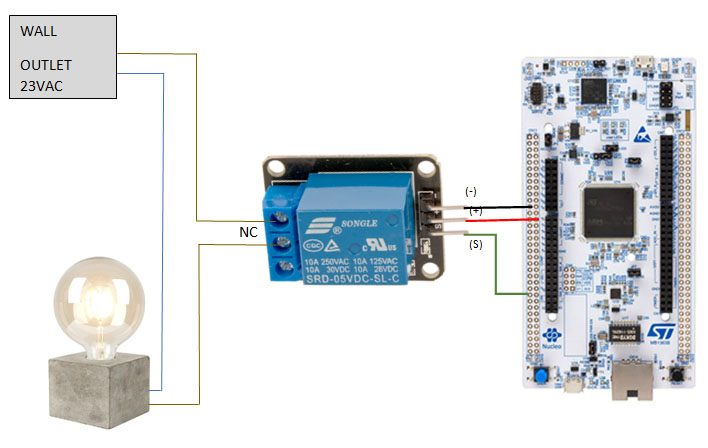
The project is showcasing a simple way of using the the BleuIO Dongle to turn on and off a light bulb that is connected to the STM32 Nucleo-144 via a 5V Relay.

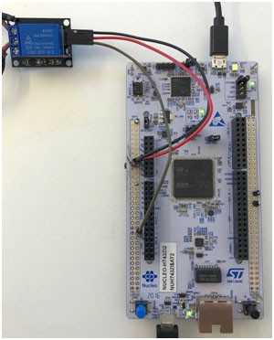
You will need two dongles, one connected to the Nucleo board and one connected to a computer, running the web script.
When the BleuIO Dongle is connected to the Nucleo boards USB port the STM32 will recognize it and directly start advertising. This allows the other Dongle to connect to it.

It will also accept 3 different inputs from the UART:

input result
0 Send ATI (Request device information) command to BlueIO Dongle.
1 Manually turn the light bulb on
2 Manually turn the light bulb off

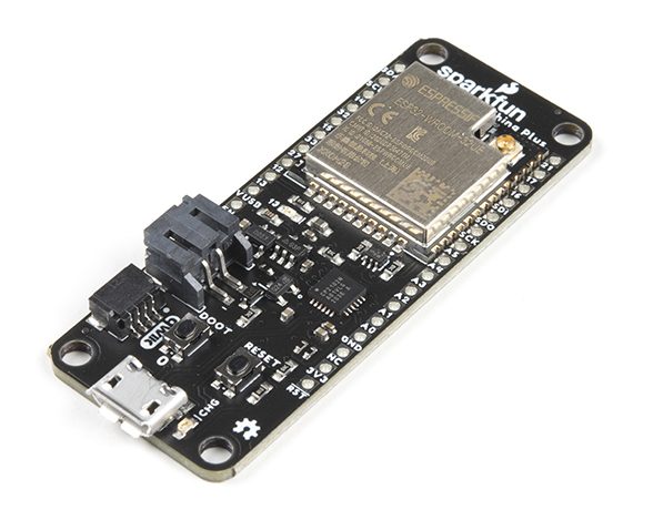
We have used an STM32 Nucleo-144 development board with STM32H743ZI MCU (STM32H743ZI micro mbed-Enabled Development Nucleo-144 series ARM® Cortex®-M7 MCU 32-Bit Embedded Evaluation Board) for this example.

If you want to use another setup you will have to make sure it supports USB Host and beware that the GPIO setup might be different and may need to be reconfigured in the .ioc file.

WARNING – THIS PROJECT INVOLVES HIGH VOLTAGES THAT CAN CAUSE SERIOUS INJURY OR DEATH. PLEASE TAKE ALL NECESSARY PRECAUTIONS, AND TURN OFF ALL POWER TO A CIRCUIT BEFORE WORKING ON IT.

2. Connecting the relay

Beware:

Always be very careful when experimenting with AC, electrical shock can result in serious injuries! NOTICE OF RISK; DISCLAIMER OF LIABILITY

Pinout and Connection to STM32 For the DC part of the Relay circuit connect S (signal) to pin PE4 on the STM32 NUCLEO board, also connect the Power supply (+) and ground (-) to +5V and GND respectively.

3. About the Code

You can get the project HERE

https://github.com/smart-sensor-devices-ab/stm32_bleuio_lightbulb_example

This project-based on our previous STM32 project (https://github.com/smart-sensor-devices-ab/stm32_bleuio_example) with these changes in the .ioc file:

In the pinout view, we set the GPIO PE4 to OUTPUT and labeled it to ‘lightbulb’.

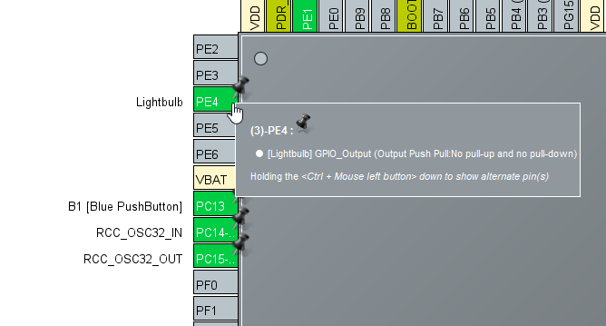
In the USBH_CDC_ReceiveCallback function in USB_HOST\usb_host.c we copy the CDC_RX_Buffer into an external variable called dongle_response that is accessible from the main.c file.

void USBH_CDC_ReceiveCallback(USBH_HandleTypeDef *phost)
{
    if(phost == &hUsbHostFS)
    {
        // Handles the data recived from the USB CDC host, here just printing it out to UART
        rx_size = USBH_CDC_GetLastReceivedDataSize(phost);
        HAL_UART_Transmit(&huart3, CDC_RX_Buffer, rx_size, HAL_MAX_DELAY);

        // Copy buffer to external dongle_response buffer
        strcpy((char *)dongle_response, (char *)CDC_RX_Buffer);

        memset(CDC_RX_Buffer,0,RX_BUFF_SIZE);
        USBH_CDC_Receive(phost, CDC_RX_Buffer, RX_BUFF_SIZE);
    }

    return;
}

In main.c we create a simple interpreter so we can react to the data we are receiving from the dongle.

/**
  * @brief Simple dongle interpreter
  * @retval None
  */
void dongle_interpreter(uint8_t * input)
{

    if(strlen((char *)input) != 0)
    {
        if(strstr((char *)input, "\r\nADVERTISING...") != NULL)
        {
            isAdvertising = true;
        }
        if(strstr((char *)input, "\r\nADVERTISING STOPPED.") != NULL)
        {
            isAdvertising = false;
        }
        if(strstr((char *)input, "\r\nCONNECTED") != NULL)
        {
            isConnected = true;
            HAL_GPIO_WritePin(GPIOE, GPIO_PIN_1, GPIO_PIN_SET);
        }
        if(strstr((char *)input, "\r\nDISCONNECTED") != NULL)
        {
            isConnected = false;
            HAL_GPIO_WritePin(GPIOE, GPIO_PIN_1, GPIO_PIN_RESET);
        }
        if(strstr((char *)input, "L=0") != NULL)
        {
            isLightBulbOn = false;
            HAL_GPIO_WritePin(Lightbulb_GPIO_Port, Lightbulb_Pin, GPIO_PIN_RESET);

            writeToDongle((uint8_t*)DONGLE_SEND_LIGHT_OFF);

            uart_buf_len = sprintf(uart_tx_buf, "\r\nLight bulb is %s\r\n", isLightBulbOn ? "on":"off");
            HAL_UART_Transmit(&huart3, (uint8_t *)uart_tx_buf, uart_buf_len, HAL_MAX_DELAY);
        }
        if(strstr((char *)input, "L=1") != NULL)
        {
            isLightBulbOn = true;
            HAL_GPIO_WritePin(Lightbulb_GPIO_Port, Lightbulb_Pin, GPIO_PIN_SET);

            writeToDongle((uint8_t*)DONGLE_SEND_LIGHT_ON);

            uart_buf_len = sprintf(uart_tx_buf, "\r\nLight bulb is %s\r\n", isLightBulbOn ? "on":"off");
            HAL_UART_Transmit(&huart3, (uint8_t *)uart_tx_buf, uart_buf_len, HAL_MAX_DELAY);
        }
    }
    memset(&dongle_response, 0, RSP_SIZE);
}

We also update the handleUartInput function so we can have manual control over the light bulb via the UART.

/**
  * @brief Simple uart input handler
  * @retval None
  */
void handleUartInput(UARTCommandTypeDef cmd)
{
    switch(cmd)
    {
        case UART_RX_0:
        {
            // 0
            uart_buf_len = sprintf(uart_tx_buf, "\r\n(0 pressed)\r\n");
            HAL_UART_Transmit(&huart3, (uint8_t *)uart_tx_buf, uart_buf_len, HAL_MAX_DELAY);
            if(isBleuIOReady)
            {
                writeToDongle((uint8_t*)DONGLE_CMD_ATI);
            } else
            {
                uart_buf_len = sprintf(uart_tx_buf, BLEUIO_NOT_READY_MSG);
                HAL_UART_Transmit(&huart3, (uint8_t *)uart_tx_buf, uart_buf_len, HAL_MAX_DELAY);
            }
            uartStatus = UART_RX_NONE;
            break;
        }
        case UART_RX_1:
        {
            // 1
            uart_buf_len = sprintf(uart_tx_buf, "\r\n(1 pressed light bulb on!)\r\n");
            HAL_UART_Transmit(&huart3, (uint8_t *)uart_tx_buf, uart_buf_len, HAL_MAX_DELAY);
            HAL_GPIO_WritePin(Lightbulb_GPIO_Port, Lightbulb_Pin, GPIO_PIN_SET);
            uartStatus = UART_RX_NONE;
            break;
        }
        case UART_RX_2:
        {
            // 2
            uart_buf_len = sprintf(uart_tx_buf, "\r\n(2 pressed light bulb off!)\r\n");
            HAL_UART_Transmit(&huart3, (uint8_t *)uart_tx_buf, uart_buf_len, HAL_MAX_DELAY);
            HAL_GPIO_WritePin(Lightbulb_GPIO_Port, Lightbulb_Pin, GPIO_PIN_RESET);

            uartStatus = UART_RX_NONE;
            break;
        }
        case UART_RX_NONE:
        {
            break;
        }
        default:
        {
            uartStatus = UART_RX_NONE;
            break;
        }
    }
}

We put the interpreter function inside the main loop.

/* Infinite loop */
  /* USER CODE BEGIN WHILE */
  while (1)
  {
    /* USER CODE END WHILE */
    MX_USB_HOST_Process();

    /* USER CODE BEGIN 3 */
    // Simple handler for uart input
    handleUartInput(uartStatus);
    // Inteprets the dongle data
    dongle_interpreter(dongle_response);

    // Starts advertising as soon as the Dongle is ready.
    if(!isAdvertising && !isConnected && isBleuIOReady)
    {
        HAL_Delay(200);
        writeToDongle((uint8_t*)DONGLE_CMD_AT_ADVSTART);
        isAdvertising = true;
    }
  }
  /* USER CODE END 3 */

4. Using the example project

4.1 What you will need

  • Two BleuIO dongles (https://www.bleuio.com)
  • The script for the dongle (available on the source code inside the web script folder)

A board with an STM32 Microcontroller with a USB port. (A Nucleo-144 development board: NUCLEO-H743ZI2, was used to develop this example. (https://www.st.com/en/evaluation-tools/nucleo-h743zi.html)

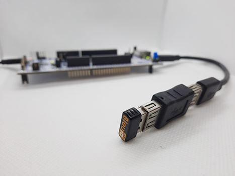
To connect the dongle to the Nucleo board a “USB A to Micro USB B”-cable with a USB A female-to-female adapter can be used.

5. How to setup project

5.1 Downloading the project from GitHub

Get project HERE

https://github.com/smart-sensor-devices-ab/stm32_bleuio_lightbulb_example

Either clone the project, or download it as a zip file and unzip it, into your STM32CubeIDE workspace.

5.2 Importing as an Existing Project

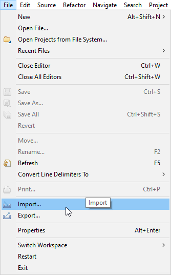
From STM32CubeIDE choose File>Import…

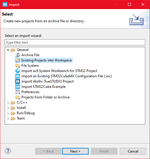
Then choose General>Existing Projects into Workspace then click ‘Next >’

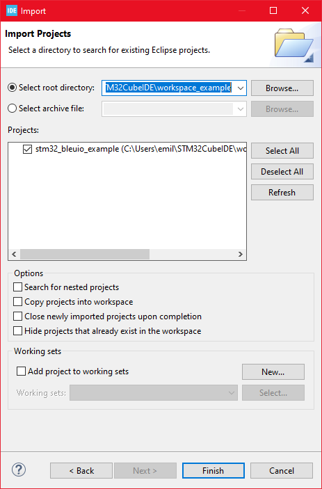
  • Make sure you’ve chosen your workspace in ‘Select root directory:’
  • You should see the project “stm32_bleuio_example”, check it, and click ‘Finish’.

6. Running the example

  • In STMCubeIDE click the hammer icon to build the project.
  • Open up the ‘STMicroelectronics STLink Virtual COM Port’ with a serial terminal emulation program like TeraTerm, Putty or CoolTerm.Serial port Setup:
    Baudrate: 115200
    Data Bits: 8
    Parity: None
    Stop Bits: 1
    Flow Control: None
  • Connect the BleuIO Dongle before running the example.
  • In STMCubeIDE click the green play button to flash and run it on your board. The first time you click it the ‘Run Configuration’ window will appear. You can just leave it as is and click run.
  • You should be greeted by this welcome message:
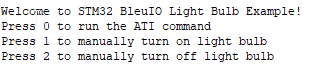
  • Wait until the message: “[BleuIO Dongle Ready]” is shown.
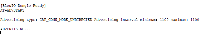
  • You can now connect with the other dongle using the script.

You can also use the UART commands (0, 1 or 2):

  • Press 0 to get device information.1 to turn on the lightbulb.2 to turn off the lightbulb.

    Dongle response will be printed to UART.

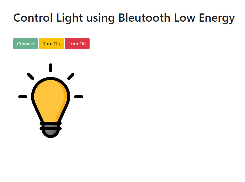
7. Controlling the light from a web browser

We wrote a simple script that connects to the dongle and sends signals to toggle the light from the web browser.

For this script to work, we need

Steps

Create a simple Html file called index.html which will serve as the frontend of the script. This Html file contains some buttons that help connect and signal to the remote dongle, which is connected to stm32.

<!DOCTYPE html>
<html lang="en">
  <head>
    <meta charset="UTF-8" />
    <meta http-equiv="X-UA-Compatible" content="IE=edge" />
    <meta name="viewport" content="width=device-width, initial-scale=1.0" />
    <link
      href="https://cdn.jsdelivr.net/npm/[email protected]/dist/css/bootstrap.min.css"
      rel="stylesheet"
      integrity="sha384-1BmE4kWBq78iYhFldvKuhfTAU6auU8tT94WrHftjDbrCEXSU1oBoqyl2QvZ6jIW3"
      crossorigin="anonymous"
    />
    <title>Control Light using Bleutooth Low Energy</title>
  </head>
  <body class="mt-5">
    <div class="container mt-5">
      <h1 class="mb-5">Control Light using Bleutooth Low Energy</h1>
      <button class="btn btn-success" id="connect">Connect</button>
      <button class="btn btn-warning" id="lightOn" disabled>Turn On</button>
      <button class="btn btn-danger" id="lightOf" disabled>Turn Off</button>
    </div>
    <div class="container mt-5">
      <img id="light" src="light_off.png" alt="" />
    </div>

    <script src="script.js"></script>
  </body>
</html>

Create a js file called script.js and include it at the bottom of the Html file. This js file uses the BleuIO js library to write AT commands and communicate with the other dongle.

import * as my_dongle from "bleuio";
const dongleToConnect = "[0]40:48:FD:E5:35:A5";
import lightOnImg from "./light_on.png";
import lightOfImg from "./light_off.png";
document.getElementById("connect").addEventListener("click", function () {
  my_dongle.at_connect();
  document.getElementById("lightOn").disabled = false;
  document.getElementById("lightOf").disabled = false;
  document.getElementById("connect").disabled = true;
});

document.getElementById("lightOn").addEventListener("click", function () {
  my_dongle
    .ati()
    .then((data) => {
      //make central if not
      if (JSON.stringify(data).includes("Peripheral")) {
        console.log("peripheral");
        my_dongle.at_central().then((x) => {
          console.log("central now");
        });
      }
    })
    .then(() => {
      // connect to dongle
      my_dongle
        .at_getconn()
        .then((y) => {
          if (JSON.stringify(y).includes(dongleToConnect)) {
            console.log("already connected");
          } else {
            my_dongle.at_gapconnect(dongleToConnect).then(() => {
              console.log("connected successfully");
            });
          }
        })
        .then(() => {
          // send command to control light
          my_dongle.at_spssend("L=1").then(() => {
            console.log("Turned on");
            document.getElementById("light").src = lightOnImg;
          });
        });
    });
});

document.getElementById("lightOf").addEventListener("click", function () {
  my_dongle
    .ati()
    .then((data) => {
      //make central if not
      if (JSON.stringify(data).includes("Peripheral")) {
        console.log("peripheral");
        my_dongle.at_central().then((x) => {
          console.log("central now");
        });
      }
    })
    .then(() => {
      // connect to dongle
      my_dongle
        .at_getconn()
        .then((y) => {
          if (JSON.stringify(y).includes(dongleToConnect)) {
            console.log("already connected");
          } else {
            my_dongle.at_gapconnect(dongleToConnect).then(() => {
              console.log("connected successfully");
            });
          }
        })
        .then(() => {
          // send command to control light
          my_dongle.at_spssend("L=0").then(() => {
            console.log("Turned off");
            document.getElementById("light").src = lightOfImg;
          });
        });
    });
});

The script js file has three button actions; connect and control light.

Now we need to know the ID of the other dongle connected to STM32 so that we can connect to it. You can use this web terminal to get the dongle ID.

- Open this site https://bleuio.com/web_terminal.html and click connect to dongle.
- Select the appropriate port to connect.
- Once it says connected, type **"ATI"**. This will show dongle information and current status.
- If the dongle is on peripheral role, set it to central by typing **"AT+CENTRAL"**
- Now do a gap scan by typing **"AT+GAPSCAN"**
- Once you see your dongle on the list ,stop the scan by pressing control+c
- Copy the ID and paste it into the script (script.js) line #2

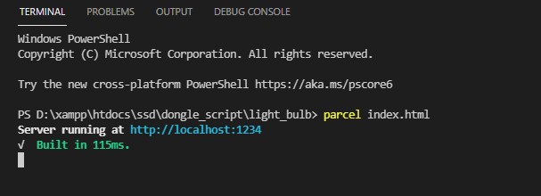
You will need a web bundler. You can use parcel.js

Once parcel js is installed, go to the root directory and type “parcel index.html”. This will start your development environment.

Open the script on a browser using parcel js.

You can easily connect to the dongle and turn on-off light from there.

Pre-Amplifier for MEMS Microphone

This is a low-cost, small-size audio pre-amplifier for MEMS microphone, OPAMP-based circuit amplifies the low-level analog signal coming from MEMS microphone to the desired level required for the next stage which is an audio amplifier, basically microphone level to line level.

Resistor R4 and R7 are used to generate a voltage reference to bias the input common-mode voltage of the op-amp at VCC/2, C7, C8, and R7 help to reduce power supply noise. R5 and C5 allow AC coupling of the microphone signal.  R2 and C2 create a low-pass gain so as not to amplify noise beyond the audio bandwidth. R3 and C6 create a high-pass gain so as not to amplify the DC biasing of the op-amp (including input offset voltage). The cut-off frequency is 59 Hz. D1 is a power LED, this board has a dual option for MEMS microphones. Users may solder onboard microphones or connect external microphones. This board is tested with external Analog MEMS microphone modules from PUI Audio which comes with 3 connections VCC, GND, and output.

Pre-Amplifier for MEMS Microphone – [Link]

BCS Series Low Illumination Film Solar Cells

TDK’s BCS series solar cells can be customized according to various shapes and applications

TDK’s BCS series are thin, lightweight, and flexible solar cells offering high power generation efficiency under fluorescent and LED light sources. The cells are made of amorphous silicon film substrate, and designs can be customized according to various shapes and applications. Because BCS series solar cells offer output stability in low and dim light, they are suitable for use in products used indoors. Additional benefits of solar cells include cost reduction in electrical wiring and battery replacement. When used in combination with a primary battery, solar cells can extend the battery life and usage time of rechargeable devices. BCS series solar cells can be used in applications such as watches, wearables, beacons, wireless sensor nodes, and other IoT power supply applications, smart cards and locks, and more.

Features

  • Thin, lightweight, and flexible
  • High power generation efficiency under fluorescent and LED light sources
  • Suitable as a power source for products used indoors
  • Output stability in low and dim light
  • Can be customized according to various shapes and applications
  • Operating temperature range from -20°C to +60°C

more information: https://product.tdk.com/system/files/dam/doc/product/solar-cell/catalog/film-solarcell_bcs_en.pdf

Maxtena M4HCT-22-P Passive GPS GLONASS Beidou Antenna

Maxtena M4HCT-22-P Passive GPS GLONASS Beidou Antenna is designed for GPS L1, GLONASS, Galileo, and Beidou bands and built on proprietary Helicore® technology. This antenna features a 3-pin connector and an ultra lightweight design of only 2 grams, making it ideal for demanding, mechanically constrained platforms. The M4HCT-22-P has a low axial ratio, is ground plane independent, and is designed for GPS, GLONASS, Galileo, and Beidou bands. Maxtena M4HCT-22-P Antenna is suitable for asset tracking, navigation devices, mining equipment, oil and gas industries, handheld devices, and military and security applications.

Features

  • GPS, GLONASS, Galileo, Beidou bands
  • Low axial ratio
  • Easy integrate 3-pin connector
  • Ultra-lightweight design of 2 grams
  • Ground plane independent

more information: https://maxtena.com/products/gps/m4hct-22-p-antenna/

SnapEDA is now available on every distributor website thanks to new Chrome extension

The new SnapEDA Chrome extension notifies electronics designers when computer-aided design (CAD) models are available and allows for one-click import into desktop CAD tools.

Today, SnapEDA, the first search engine for electronics design is launching a new Chrome extension to allow electronics designers to find CAD models on every distributor website.

The new SnapEDA Chrome extension automatically notifies designers when a CAD model is available. The CAD model can then be added to a desktop printed circuit board (PCB) design tool with just one click.

The extension pairs with the new SnapEDA Desktop application, which creates a bridge between the web for component research and the desktop design environment. It provides three types of CAD models: schematic symbols, PCB footprints and 3D models. Supported formats include Eagle, Altium and KiCad, and there are more coming soon.

Over the last year, SnapEDA has been expanding the SnapEDA Syndication Network, which now has 35 affiliated partners including distributors, PCB design tools, and media sites, with 12 new partners added in 2021 alone. The SnapEDA Chrome extension is especially helpful on websites that haven’t yet joined the SnapEDA Syndication Network as it now allows engineers to find CAD models on those websites.

Since founding the pioneering search engine for E-CAD in 2013, SnapEDA has been furthering its mission of helping engineers design electronics faster by removing barriers. Since then, SnapEDA has continued to launch new products into the market including its patented CAD model verification technology, the first E-CAD request service InstaPart, and the first computer-vision based schematic generator InstaBuild. The new SnapEDA Desktop application and pairing Chrome extension are the latest examples of their continued dedication to improve the workflows of engineers.

The SnapEDA Chrome extension is free and can be downloaded at www.snapeda.com/chrome

Universal OPAMP Board for SMD MSOP8 Package

This is easy to build and very useful project for hobbyists and students to learn and create OPAMP-based projects. The project accommodates a single OPAMP in the MSOP8 package. The project provides the user with multiple choices and extensive flexibility for different applications circuits and configurations. It provides the user with many combinations for various circuit types including active filters, differential amplifiers, and external frequency compensation circuits. A few examples of application circuits are given below. OP777 op-amp is the right choice to use or any other MSOP8 op-amp with the same pin configuration as OP777 can be used. It supports dual supply or single supply, Jumper J1 is provided to use this board with a single supply, D1 is the power LED.

Universal OPAMP Board for SMD MSOP8 Package – [Link]

TOP PCB Companies