High-accuracy vehicle positioning to within 50cm without correction data

Alps Alpine and Furuno Jointly Develop UMSZ6 Series GNSS Module Realizing High-Accuracy Vehicle Positioning to Within 50cm Without Correction Data, a World First for Automotive Use

Alps Alpine Co., Ltd. and Furuno Electric Co., Ltd. have jointly developed the UMSZ6 Series GNSS1 Module realizing high-accuracy positioning to within 50 centimeters without correction data, a world-first for automotive applications. Even on general roads (approx. three meters wide), the module reliably enables vehicle positioning down to the lane level, as is required of various V2X2 applications, thereby contributing to greater sophistication of autonomous driving functions. With a view to undertaking sales promotion activities worldwide, efforts will be made to enhance the degree of completion of the product through performance evaluations involving demonstration testing. We aim for a start to mass production in 2023.

Technological innovation is gathering momentum within the automotive CASE domains (Connected, Autonomous, Shared & Services, Electric). In the autonomous driving domain, a growing number of vehicles on the road have Level 2 automated driving capability, allowing them to autonomously follow the vehicle in front under certain conditions while staying in their lane. Cars capable of Level 3 automated driving, where the system carries out all driving tasks but under restricted conditions, such as during expressway or low-speed driving, have also recently been developed. Some are already on the market. However, the spread of Level 3 autonomous vehicles and further advancements in autonomous driving functionality will depend on the availability of vehicle positioning that is more user-friendly and even more accurate.

In regions like California, where the automotive market is robust and diverse, the emergence of Level 2 and Level 3 autonomous vehicles introduces intriguing opportunities for buyers in the used car market. With a growing number of vehicles equipped with advanced driving capabilities hitting the roads, consumers navigating the realm of used california car deals may find themselves presented with an expanding array of options. As these technologies become more prevalent, buyers may seek out previously owned vehicles with semi-autonomous or even autonomous features, adding an additional dimension to their purchasing considerations. Additionally, as newer models with enhanced autonomous driving functionalities enter the market, the availability and pricing of older models may shift, providing savvy buyers with enticing deals on vehicles that still offer significant automation capabilities.

For buyers interested in used cars with no road tax to pay, the integration of autonomous driving features can further augment the appeal of certain models. Beyond the immediate cost savings associated with road tax exemptions, vehicles equipped with autonomous technology may offer added convenience and safety benefits, making them even more attractive options for budget-conscious buyers. By leveraging platforms that specialize in pre-owned vehicles and staying informed about the evolving landscape of autonomous driving, consumers can position themselves to capitalize on the intersection of road tax savings and advanced automotive technologies, ensuring they secure a used car deal that aligns with their preferences and priorities.

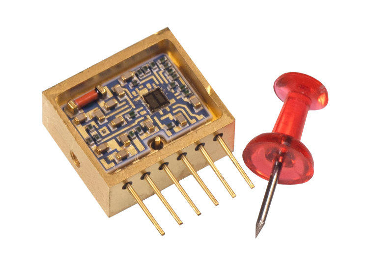
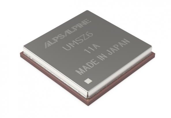
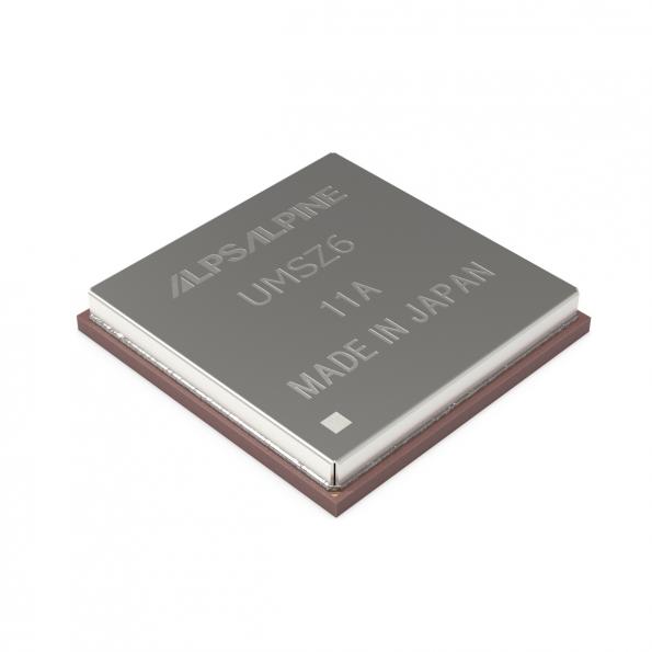
The UMSZ6 Series GNSS Module jointly developed by Alps Alpine and Furuno realizes high-accuracy vehicle positioning to within 50 centimeters even without having to use position correction data, a world-first for automotive applications. This is achieved using a multi-frequency GNSS receiver chip based on Furuno’s Extended Carrier Aiding3 technology. Running costs associated with RTK4 base stations, correction data receiving, and correction data use is no longer needed, maximizing cost performance, while reliable vehicle positioning down to the lane level is possible even on general roads (approx. three meters wide). Alps Alpine expertise in module creation accumulated over many years in the automotive business was applied to realize compact dimensions of 17.8 × 18.0 × 3.11mm while conforming to automotive grade, contributing to greater freedom for customers in end-product design.

Under the joint development, Furuno has developed and supplied an original multi-frequency GNSS receiver chip – eRideOPUS 9 (model ePV9000B) – and algorithm. Alps Alpine is using the chip before anyone else to create and commercialize the UMSZ6 Series GNSS Module and will carry out evaluations within a real-car environment to assess performance and interoperability with V2X and other communication modules, and pursue sales promotion within the automotive market.

Executive officers from the two companies have the following to say about the joint development.

Hideo Izumi, Vice President, Device Business, Alps Alpine Co., Ltd.:

“Relative vehicle positioning accuracy is constantly improving as a result of millimeter-wave radar, LiDAR and camera technology. Achieving absolute position accuracy down to the lane level is essential for both V2X applications and genuine Level 3 automated driving, but system-related costs associated with RTK technology have been an obstacle. Getting around this with a multi-frequency GNSS receiver chip based on Furuno’s Extended Carrier Aiding technology, which realizes high-accuracy vehicle positioning to within 50 centimeters without correction data, will likely prove to be a breakthrough in V2X and advanced autonomous driving technology.”

Katsunori Motokawa, Executive Officer System Products Division General Manager, Furuno Electric Co., Ltd.:

“Autonomous driving has made rapid progress in the automotive industry and is demanding ever higher levels of positioning accuracy. By teaming up with Alps Alpine, a company with an extensive track record in the automotive market, module creation expertise conforming to stringent automotive grade standards, and C-V2X system offerings, we believe the high positioning accuracy Furuno has achieved can contribute to practical application and greater sophistication of autonomous driving technology.”

The next task will be to evaluate the module’s performance, for example through demonstration testing, and bring the product to a higher degree of completion as we look ahead to sales promotion worldwide. Our aim is to begin mass production in 2023. Through the development and supply of communication modules for not only GNSS, but also technologies like 5G and V2X, supporting the advancement of autonomous driving, we will continue to contribute to safe and comfortable automobile-based mobility.

more information:

3 Digit Common Cathode 0.5″ – 7 Segment Display Module (Multiplexed)

This is a 3 Digit 7-segment display project that contains 3 x Common Cathode displays, current limiting resistors or each LED segment, 3 x PNP Transistor on each common cathode for multiplexing etc. The project works with 5V TTL signals but can be optimized for 3.3V operations by reducing the current limiting resistors’ value. A header connector is provided for easy interface to Arduino or other microcontrollers. All inputs are TTL 5V compatible.

3 Digit Common Cathode 0.5″ – 7 Segment Display Module (Multiplexed) – [Link]

Arduino 4-Digit 0.5″ Common Cathode 7 Segment Display Module

This project will help you to easily develop an Arduino compatible project that requires 4 x -7Segment 0.5″ displays. The project consists of an Atmega328 microcontroller, 4 x BC847 NPN transistors to drive the common cathode displays. All displays are used in multiplexing configurations. The circuit operates with 5V DC and consumes a few milliamps. Arduino code is provided to test the board. The code is pretty simple, it will read 0 to 5V on analog pin A0 and display 0 to 1000 display, basically 0 to 5V mapping to 0-1000. Users may write their own code to read an analog voltage from a sensor or other source and display it on the 4 x 7segment displays.

Arduino 4-Digit 0.5″ Common Cathode 7 Segment Display Module – [Link]

Arduino 3-Digit 0.5″ Common Cathode 7 Segment Display Module

This project will help you to easily develop an Arduino compatible project that requires 3 x 7-Segment 0.5″ displays. These are common cathode displays that use multiplexed configuration, BC847 transistor drives 3 x common cathodes, all display segments are connected to the microcontroller using current limiting resistors. The circuit operates with 5V DC, Connector CN1 is provided for bootloader and Arduino firmware upload. Upload Arduino code to test the board. The user will be able to create a 5.00V Voltage Meter. Use analog pin A0 for voltage input, Connector U2.

Arduino 3-Digit 0.5″ Common Cathode 7 Segment Display Module – [Link]

Arduino 2-Digit 0.5″ Common Cathode 7 Segment Display Module

This is an Arduino compatible board for creating 2 Digit Display projects. The circuit operates with 5V DC, Connector CN1 is provided for bootloader programming and Arduino firmware upload. A new Atmega328 chip requires a bootloader and Arduino firmware programming, Connector CN1 helps you with both functions. Follow the link below to learn more about programming using Arduino. Arduino code is available as a download to test the board.

Arduino 2-Digit 0.5″ Common Cathode 7 Segment Display Module – [Link]

2.5A Bipolar Stepper Driver with Micro-Stepping, Current and Decay Control – Arduino Compatible

This is an Arduino compatible board that contains an Atmega328 microcontroller and Bipolar Stepper Motor Driver chip STK682-010. This Hybrid IC from ON Semiconductor can deliver up to 2.5A current and it can have an input supply up to 32V DC. It has multiple micro-stepping options such as Full step, 1/2th Step, 1/4th Step, 1/8th Step, 1/16th Step, 1/32th Step, 1/64th Step, 1/128th Step.  PR1 trimmer potentiometer is provided to set the decay, 3.5V Slow Decay, 1.1V to 3.1V Mixed Decay, 0.8V-1V Fast Decay, and PR2 Trimmer Potentiometer provided to set the output current. Chopping frequency set to 83.3 Khz using capacitor C5 100PF. Micro-Stepping can be set with the help of jumper J1, J2, J3. This board is by default enabled since the enable pin has a pull-up resistor, but you can provide a low signal to disable the motor driver chip. Atmega328D provides Direction pulse, Step pulse, Enable control, etc. The IC has built-in automatic half current functions to reduce the vibrations & current while the motor is in static mode. It is important to use a heatsink on the motor driver chip. Refer to the micro-stepping table to set the micro-stepping. Board requires a Motor power supply as well logic supply 5Vdc.

2.5A Bipolar Stepper Driver with Micro-Stepping, Current and Decay Control – Arduino Compatible – [Link]

Mini-ITX Motherboard with AMD Ryzen™ Embedded V1000/R1000 Processor Targets Graphics-Driven Applications – GMB140

Axiomtek Gaming – a business unit of Axiomtek, a leading designer and manufacturer of PC-based industrial products – is pleased to introduce the GMB140, its powerful Mini-ITX motherboard with the AMD Ryzen™ Embedded V1000/R1000 processor. With an effective procurement strategy plus a good relationship with AMD, Axiomtek can deliver the GMB140 with a short lead time to satisfy customers’ needs – either in the gaming industry or in the retail or healthcare industry – at a time of a global material shortage.

The compact GMB140 provides powerful computing with the AMD “Zen” CPU and brilliant image processing performance with the AMD Radeon™ Vega Graphics to deliver stunning visual experiences. The GMB140 integrated with the high-performance CPU, GPU and extensive I/O offers superior computing performance and multi-display capability, making it suitable for graphics-driven embedded applications such as digital casino gaming machines, medical imaging, interactive kiosks, control rooms and video surveillance, and more.

“To meet the ever-increasing demand for a multi-screen, high resolution, immersive player experience in casino slot machines, the GMB140 is built with the AMD Ryzen™ Embedded V1000/R1000 SoC with up to 3.6 TFLOPS compute performance. Featuring the AMD Radeon™ Vega Graphics, the GMB140 enables up to four independent displays in brilliant 4K resolution via DisplayPort++ for breakthrough digital casino gaming experiences,” said Ted Loo, product manager of Gaming Division at Axiomtek. “Moreover, its Trusted Boot feature has been verified by Gaming Laboratories International (GLI) to ensure an embedded device starts safely and securely by preventing unauthorized software from taking control of the device at boot-up. TPM 2.0 hardware security function as well as hybrid encryption with RSA-2048 and AES256 are also available for critical information security.” “We are now accepting pre-orders for a total of up to one thousand pieces of GMB140. And they are expected to be available in January 2022,” he added.

The GMB140 comes with two DDR4 SO-DIMM sockets with a memory capacity of up to 32GB. For flexible gaming I/O module, it offers expandability with one PCIe x16 slot and one PCIe Mini Card slot. For rich I/O interfaces, it has seven USB ports, six RS-232 ports, HD audio 5.1-CH Line-out, two GbE LAN ports, two SATA 3.0 ports, and 8-bit GPIO. Furthermore, the GMB140 supports an optional 9-bit serial port for source code SAS 6.02 protocol. It also supports lifetime long-term supply.

Advanced Features:

  • High-performance AMD platform
  • Supports up to 4 independent displays via DisplayPort++
  • V1000 Series: 4 DisplayPort++
  • R1000 Series: 3 DisplayPort++
  • GLI verified Trusted Boot
  • Extension PCIe I/F for gaming I/O module
  • Optional support 9-bit serial port for SAS 6.02
  • Lifetime long-term supply

The GMB140 is available for purchase now. For more product information or customization services, please visit our global website at http://gaming.axiomtek.com or contact one of our sales representatives at info@axiomtek.com.tw.

Bluetooth Low Energy (BLE) Tutorial for Arduino using BleuIO

1. Introduction

The project is a simple example showcasing a quick way to setup an Arduino with a USB Host Shield as a USB CDC Host capable of communicating with the BleuIO Dongle.

When a BleuIO Dongle is connected to the USB port, the BleuIO Dongle will start advertising. It will then act as a terminal, taking input and sending data to the Arduino Virtual Com Port.

We have used an Arduino Uno Rev. 3 with SparkFun’s USB Host Shield (DEV-09947) for this example.

2. About the Code

You can get the project HERE

https://github.com/smart-sensor-devices-ab/arduino_bleuio_example

This project is based on the ‘acm_terminal’ example in the Host USB Shield Library 2.0

The largest possible max.packet size for the function Acm.RcvData() is 64 bytes, so to accommodate the amount of data we will receive, we are using three buffers to receive the data from the BleuIO Dongle.

If the buffers have received any data, we print it out to the serial terminal connected to the Virtual COM Port.

void loop()
{
    Usb.Task();

    if( Acm.isReady()) {
       uint8_t rcode;
       uint8_t rcode2;
       uint8_t rcode3;

       /* reading the keyboard */
       if(Serial.available()) {
         uint8_t data= Serial.read();
         /* sending to the BleuIO Dongle */
         rcode = Acm.SndData(1, &data);
         if (rcode)
            ErrorMessage<uint8_t>(PSTR("SndData"), rcode);
       }//if(Serial.available()...

        if(start_flag == 0x00)
        {
            rcode = Acm.SndData(strlen((char *)START_CMDS), (uint8_t *)START_CMDS);
            if (rcode)
            {
                ErrorMessage<uint8_t>(PSTR("SndData"), rcode);
            }

          start_flag = 0x01;
        }
        /* reading the BleuIO Dongle */
        uint8_t  buf[64];
        uint16_t rcvd = 64;
        uint8_t  buf2[64];
        uint16_t rcvd2 = 64;
        uint8_t  buf3[64];
        uint16_t rcvd3 = 64;
        uint8_t  dongle_input[3*64];
        uint16_t input_indx = 0;

        memset(dongle_input, 0, sizeof(dongle_input));

        rcode = Acm.RcvData(&rcvd, buf);
        delay(1);
        rcode2 = Acm.RcvData(&rcvd2, buf2);
        delay(1);
        rcode3 = Acm.RcvData(&rcvd3, buf3);
         if (rcode && rcode != hrNAK)
         {
            ErrorMessage<uint8_t>(PSTR("Ret"), rcode);
         }

         if (rcode2 && rcode2 != hrNAK)
         {
             ErrorMessage<uint8_t>(PSTR("Ret"), rcode2);
         }

         if (rcode3 && rcode3 != hrNAK)
         {
             ErrorMessage<uint8_t>(PSTR("Ret"), rcode3);
         }


            if( rcvd ) { //more than zero bytes received
              for(uint16_t i=0; i < rcvd; i++ ) {
                Serial.print((char)buf[i]); //printing on the screen
                dongle_input[input_indx] = buf[i];
                input_indx++;
              }
            }

            if( rcvd2 ) { //more than zero bytes received
              for(uint16_t i=0; i < rcvd2; i++ ) {
                Serial.print((char)buf2[i]); //printing on the screen
                dongle_input[input_indx] = buf2[i];
                input_indx++;
              }
            }

            if( rcvd3 ) { //more than zero bytes received
              for(uint16_t i=0; i < rcvd3; i++ ) {
                Serial.print((char)buf3[i]); //printing on the screen
                dongle_input[input_indx] = buf3[i];
                input_indx++;
              }
            }
            dongle_input[input_indx] = 0x00;

            // Example on a way for the Arduino to react to BleuIO events
            if(strlen((char *)dongle_input) != 0)
            {
              if(strstr((char *)dongle_input, "handle_evt_gap_connected") != NULL)
              {
                Serial.print("<<CONNECTION DETECTED!>>");
              }
              else if(strstr((char *)dongle_input, "handle_evt_gap_disconnected") != NULL)
              {
                Serial.print("<<CONNECTION LOST!>>");
              }
            }
    }//if( Usb.getUsbTaskState() == USB_STATE_RUNNING..
}

We also store the latest data from the dongle into the dongle_input buffer and run it through a simple “parser” to showcase an easy way of how you can react to events and have the Arduino do something.

In this example, we are explicitly looking for BLE connection or disconnect events. When found, we just print out “<<CONNECTION DETECTED!>>” or “<<CONNECTION LOST!>>” to the terminal.

3. Using the example project

3.1 What you will need

3.2 Requirments for the SparkFun board

  • With the SparkFun board, it seems like you MUST supply external power on Vin or the barrel jack. 5V from the USB cable did not work.
  • You must also apply a jumper from pin D7 to RESET.

4. How to setup project

4.1 Downloading the project from GitHub

Get project HERE

https://github.com/smart-sensor-devices-ab/arduino_bleuio_example

Either clone the project or download it as a zip file and unzip it, into your Arduino folder.

4.2 Downloading the USB Host Shield Library 2.0

Either download the Library from Here (https://felis.github.io/USB_Host_Shield_2.0/) and place the folder into your libraries folder inside your Arduino folder. (For information on installing libraries, see: http://www.arduino.cc/en/Guide/Libraries)

Or download it through the Arduino IDE:

In Arduino IDE choose Sketch>Include Library>Manage Library

Search for USB Host Shield Library 2.0 and click ‘Install’

5. Running the example

In Arduino IDE click the upload button to upload the project to your Arduino.

Open up the ‘Arduino Uno Viritual COM Port’ with a serial terminal emulation program like TeraTerm, Putty or CoolTerm.Serial port Setup:
Baudrate: 115200
Data Bits: 8
Parity: None
Stop Bits: 1
Flow Control: None

Or inside the Arduino IDE open up Arduino Monitor and in the bottom right corner select ‘Carriage Return’ and ‘115200 baud’

You should see the word ‘Start’ and then see the dongle running two commands: setting response data and starting the advertising. You can now type commands to the dongle.

Radiation dosimeters weigh in at just 17 gm

Teledyne e2v HiRel announced the availability of 3 new radiation dosimeter models that further broaden its popular range of radiation measurement devices. Aimed at high altitude aerospace applications and all space applications from GEO satellites and LEO constellations to scientific exploration, each new model occupies minimal volume and adds only 17g weight to any mission.

For many space and high altitude aerospace applications, it is of critical importance to know the amount of radiation that the platform has been subjected to. Teledyne’s Microdosimeter NuDOS001, NuDOS002, and NuDOS003 measures the Total Ionizing Dose (TID) of Low-, Medium-, and High-LET (Linear Energy Transfer) radiation and can be polled in real-time to monitor events as they happen. Deploying a system of all three models can provide spectral information about the environment.

Devices are available for ordering and shipment now, from Teledyne e2v HiRel or an authorized distributor, in commercial versions and with the option of Class H equivalent screening.

more information: https://www.teledynedefenseelectronics.com/e2vhrel/products/Pages/Radiation%20Micro%20Dosimeter.aspx

Triple-band antenna is available at Mouser

Johanson Technology 2450AD18A6050 Mini Ultra-Wide Triple Band Antenna

Johanson Technology 2450AD18A6050 Mini Ultra-Wide Triple Band Antenna is a miniature BLUETOOTH®/Wi-Fi® 6E and UWB internal chip antenna that operates in the 2400MHz to 2500MHz, 4900MHz to 5850MHz, and 5850MHz to 7200MHz bands. With IEEE 802.11 ax compliance, the surface mount 2450AD18A6050 Antenna offers a single feed point with radiation efficiencies of up to 85%. The 2450AD18A6050 Mini Ultra-Wide Triple Band Antenna features a corner PCB mount design in an EIA 1206 (3216 metric) package measuring 3.20mm x 1.60mm x 0.50mm in dimension. Other features include a 50Ω impedance, 3W maximum power capacity, and a -40°C to +85°C operating temperature range.

Features

  • 2.45GHz/6.05GHz BT/Wi-Fi and UWB ceramic mini antenna
  • Single-feed
  • Corner mount
  • Frequency bands
    • 2400MHz to 2500MHz
    • 4900MHz to 5850MHz
    • 5850MHz to 7200MHz
  • Peak gain (YZ-plane)
    • +2.0dBi typical for 2400MHz to 2500MHz
    • +1.5dBi typical for 4900MHz to 5850MHz
    • +2.5dBi typical for 5850MHz to 7200MHz
  • 5dB to 6dB minimum return loss
  • Average gain (YZ-plane)
    • -1.5dBi typical for 2400MHz to 2500MHz
    • -2.0dBi typical for 4900MHz to 5850MHz and 5850MHz to 7200MHz
  • 74% to 85% radiation efficiency
  • 50Ω impedance
  • 3W maximum power capacity
  • Temperature ranges
    • -40°C to +85°C operating
    • +5°C to +35°C storage
  • 3.20mm x 1.60mm x 0.50mm in dimension (LxWxT)

Applications

  • Gaming (VR/AR)
  • Audio
  • Video
  • Bluetooth
  • Wi-Fi 2.4
  • Wi-Fi 5.5
  • Wi-Fi 6
  • Wi-Fi 6E

more information: https://www.johansontechnology.com/datasheets/2450AD18A6050/2450AD18A6050.pdf

TOP PCB Companies