Rohde & Schwarz adds new frequency ranges to its portable all-rounder spectrum analyzers

New base models for the portable R&S FPL1000 take spectrum and signal analysis capabilities up to 26.5 GHz. They combine the functionality of benchtop instruments and the portability of a handheld instrument, with intuitive features to make high-performance measuring on the go fast and simple.

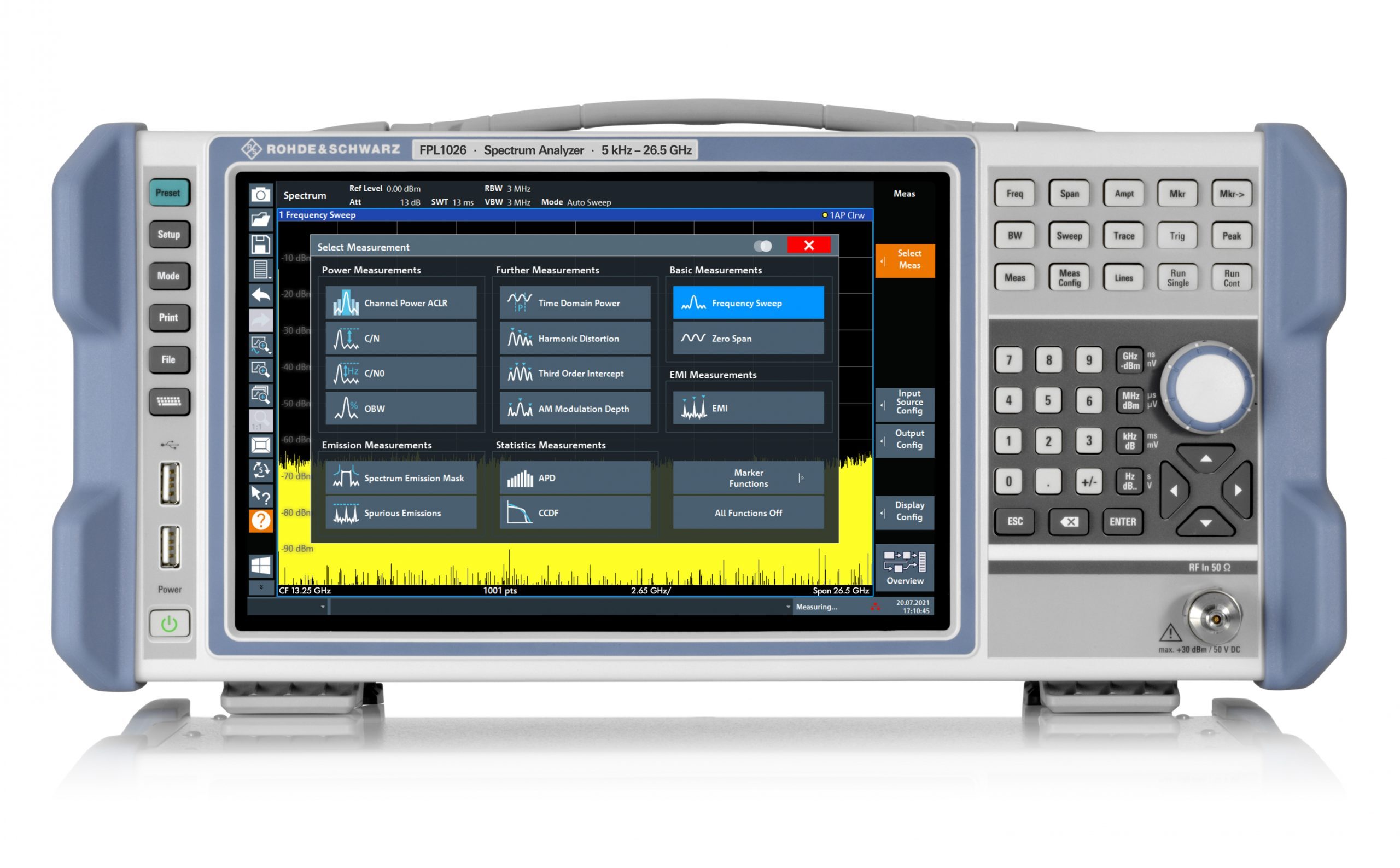
The R&S FPL1000 spectrum analyzer combines the functionality of benchtop instruments and the portability of a handheld instrument.

Rohde & Schwarz has extended its popular R&S FPL1000 family with the introduction of new base models offering measurement frequencies up to 26.5 GHz. For the series, two new models have been added to the range, providing capabilities from 5 kHz to 14 GHz and 5 kHz to 26.5 GHz.

The R&S FPL1000 is a single measuring instrument for general purpose applications and various types of measurements. It can analyse signals with a bandwidth of 40 MHz, and it is the only instrument in its class with battery operation that features an internal generator up to 7.5 GHz. It is the go-anywhere instrument for spectral measurements, for highly accurate power measurements with power sensors and for analysing analogue and digitally modulated signals. Even in its basic configuration, the R&S FPL1000 is quick and intuitive for measurements including: spectrum analysis with measurement functions such as channel power, ACLR, signal-to-noise ratio, spurious, harmonic distortions, third-order intercept point, AM modulation depth. Capabilities extend further to include statistical ADP and CCDF analysis and versatile marker functions.

Measurement applications are also available for analysing analogue and digitally modulated signals. The R&S FPL1-K7 option turns the R&S FPL1000 into an analogue modulation analyzer for amplitude, frequency and phase-modulated signals. The base unit’s I/Q analyzer supports the magnitude and phase presentation of I and Q within the analysis bandwidth. The I/Q data can be exported for further analysis with third-party software products. The R&S FPL1-K54 provides EMI measurements for diagnostics of RF interference. The R&S FPL1-K70 vector signal analysis option also characterises digitally modulated single-carrier signals. There are additional options for multi-modulation analysis and measurement of BER on PRBS data.

The R&S FPL1000 family delivers solid RF performance: typical phase noise is -108 dBc at 10 kHz offset (1GHz carrier), together with displayed average noise level (DANL) of 
-163 dBm using the optional pre-amplifier. Performance, affordability, and ease-of-use make the R&S FPL1000 the ideal instrument for use in the lab, monitoring satellite ground stations, and communication links, education, test houses, in production, and in service facilities.

The R&S FPL1000 spectrum analyzers with new frequency ranges are part of the R&S Essentials portfolio. All models are now available from Rohde & Schwarz and selected distribution partners.

more information: https://www.rohde-schwarz.com/us/home_48230.html

Teledyne LeCroy’s LCR meters are compact and are equipped with diverse measurement functionalities

Teledyne LeCroy’s T3LCR series of high-precision LCR meters offers three models with a maximum test frequency ranging from 2 kHz to 300 kHz and basic accuracy of 0.05%. The T3LCR meters are compact and are equipped with diverse measurement functionalities, making them an excellent choice in meeting the requirements of R&D, component assessment for engineering departments, sorting, and quality control in production environments.

The T3LCR series provides a rich set of functionalities while maintaining a compact size. The entire series adopts a 3.5″ color LCD and features clearly displayed parameters. In addition to simultaneously displaying setting criteria and measurement results, the series also includes two additional monitoring parameters. The four parameters (primary + secondary and two monitoring) are simultaneously shown on the screen that enhances the measurement efficiency. The enlarged display mode not only emphasizes the measurement results but also provides PASS/FAIL results to facilitate a rapid and convenient validation process.

The T3LCR series also features a range of ancillary measurements to meet the measurement requirements of different materials. For instance, the T3LCR series provides the automatic level control (ALC) function to satisfy the test voltage requirement of MLCC devices. For inductive component measurements, the T3LCR series provides the adjustable test current function and the DC resistance measurement function. With respect to the DC bias voltage test for capacitive components requirements, the T3LCR series allows users to conduct verification measurements on materials by using its internal ±2.5 V adjustable voltage. Furthermore, to observe the trend of the DUT characteristics, a list of up to 10 functional steps allows users to set testing parameters (either by frequency, voltage, or current) for each step, based on the user’s requirements.

The T3LCR meter’s list measurement feature can be used to perform automatic sweep measurements. The sweep measurements can be performed by listing up to 10 swept frequency or amplitude (voltage/current) points. Up to 10,000 measured readings can be saved to an internal buffer. These readings can then be exported to an external USB drive in a .csv file format.

For the external control, the T3LCR series comes equipped with a Handler interface, RS-232C, and USB interface. Handler outputs 10 BIN (9 BIN, AUX: 1 BIN) sorting results that are suitable for external control; for example, controlling a component sorting operation based on the measurement results obtained by the LCR meter. RS-232 and USB are suitable for remote control operation as well as to retrieve measurement results. Additionally, the free PC software gives users an instant tool to store measurement results.

Features

  • 3.5″ color LCD
  • Continuous test frequency
  • Basic accuracy of 0.05%
  • Measuring speed: 25 ms (max)
  • Suitable for MLCC testing
  • Spot frequency or full frequency range OPEN/SHORT correction
  • 16 major/secondary parameter measurement combinations and two additional monitoring parameters (maximum of four different parameters can be shown simultaneously)
  • DCR measurement and internal D.C. bias voltage (±2.5 V)
  • PASS/FAIL result
  • Auto level control (ALC) function
  • BIN function provides 10 BIN (9 BIN, AUX: 1 BIN)
  • List measurement feature to perform automated sweep measurements by listing up to 10 frequency or amplitude points
  • Standard interface: RS-232C, USB, Handler, and USB storage
  • Compact size, ideal for automatic equipment (2U, 1/2 rack)

more information: https://teledynelecroy.com

TFT display module features contrast ratio of 900:1

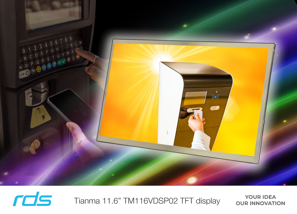
An 11.6-inch Tianma TFT display module is in stock at distributor Review Display Systems (RDS).

The TM116VDSP02 features Full HD (1920 x 1080 pixels) resolution, a 16:9 wide aspect ratio, a high brightness rating, and exceptional optical performance characteristics.

Ideal for use in high ambient light and outdoor environments, the Tianma TM116VDSP02 is manufactured with an anti-glare surface polariser and supports 88° wide viewing angles in all directions (up/down, left/right).

Supporting a brightness specification of 1600cd/m² and a contrast ratio of 900:1, display images are bright, colorful, and concise. The white LED backlight has a 50K hour half brightness lifetime.

Typical applications include graphical user interfaces (GUI) for ticketing systems, information terminals, point-of-sale equipment, marine navigation, and in-vehicle systems.

Justin Coleman, display division manager, RDS said,

“The high brightness Tianma 11.6-inch TFT display module provides a versatile and highly capable display solution for a wide range display applications particularly those where high levels of ambient or outdoor light may be present. Additionally, RDS can offer advice, design-in support and expertise for customers developing display-based products for a wide range of applications and equipment.”

The 11.6inch display module has mechanical outline dimensions of 273.5mm (w) x 166.5mm (h) x 7.8mm (d) and an active display area of 256.3mm (w) x 144.2mm (h).

A wide operating temperature range of -20°C to +80°C enables operation in extreme operating environments.

The 30-pin data interface supports dual-channel 24-bit LVDS and 8-bit RGB color data enabling a color palette of up to 16.7m colors.

Review Display Systems have extensive experience and knowledge designing and developing fully integrated embedded systems utilizing the latest display and embedded computing technology.

The 11.6-inch Tianma TM116VDSP02 TFT display module is now available immediately from Review Display Systems.

Representing leading global manufacturers, RDS supports a comprehensive range of display technologies, touch screen,s and embedded computing solutions.

more information: https://www.tianma.eu

Lynred boosts thermal sensitivity across range of 12-micron infrared detectors

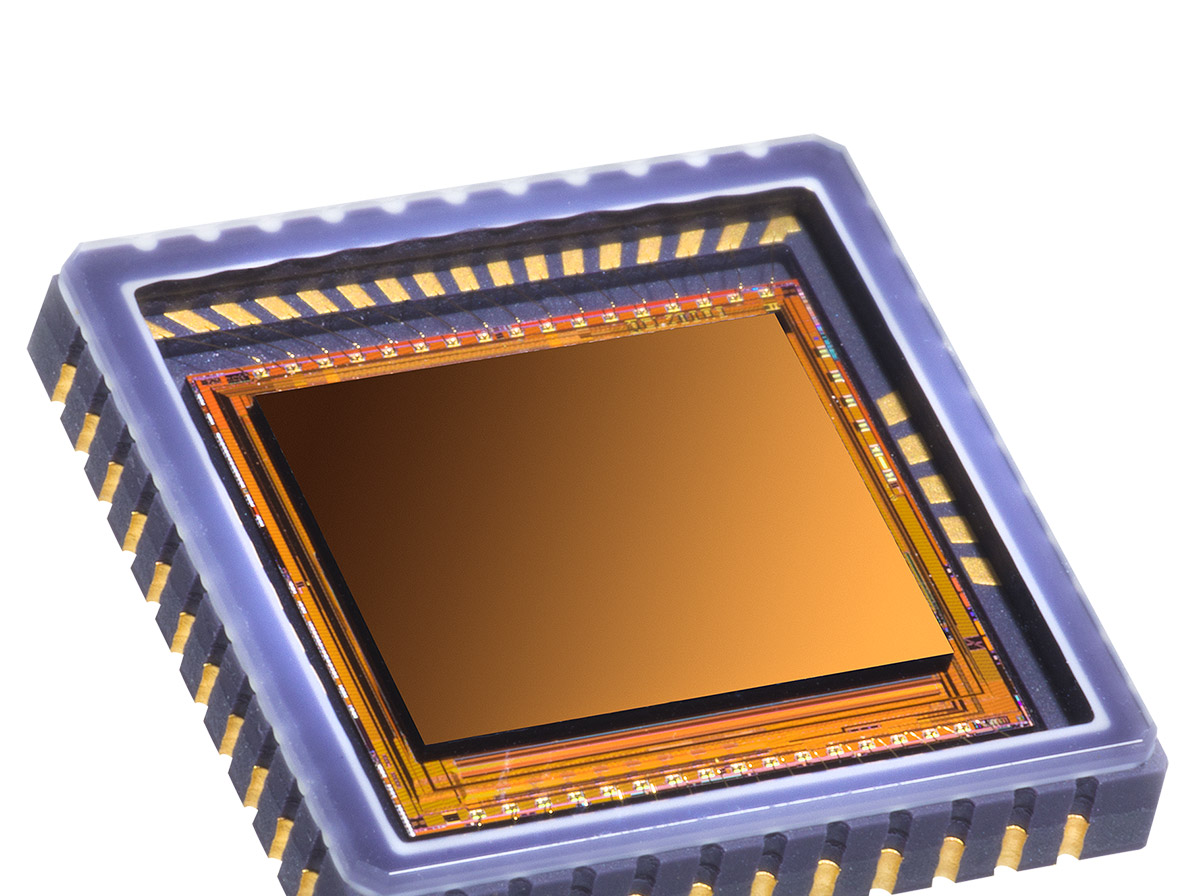
Lynred has announced enhanced capabilities across the range of its 12µm infrared detectors, to enable optronic systems to more accurately identify objects in low-contrast scenes.

These 12 µm pixel pitch infrared detectors, based on a microbolometer technology, come with enhanced thermal sensitivity, permitting use in limitless applications.

Applications include integration into outdoor leisure equipment for use at dawn or at night.

Lynred’s range of 12 µm microbolometers is suitable for enabling optronics systems to deliver the image quality end-users seek to observe nature in early forest mist and in all-weather conditions.

“Lynred is proud to have increased the maturity and strength of its entire range of 12µm thermal imaging microbolometers,” said Jean-Yves Dussaud, Chief Marketing Officer at Lynred.

“These higher sensitivity advancements enable us to better respond to the diversified needs in new markets.”

The 12µm pixel pitch microbolometer is the emerging standard for producing smaller thermal cameras that use space-saving optics. NETD (noise equivalent temperature difference) is one of several key parameters used to evaluate the image quality of optronics systems and thermal cameras. With Lynred’s 12µm products, customers will benefit from gains in the performance of their NETD lower than 40 or 50mK, depending on the product grade, and other performance criteria: scene dynamics and mechanical robustness.

Range of 12 µm products

  • Atto320-02: a compact and low-power consumption 320×240 digital 12µm microbolometer offering fluid and crisp images – available Q1 2022
  • Atto640-02: a compact, low power 640×480 12µm microbolometer (in analogue and digital formats) for SWaP (size, weight and low-power) applications, offering fluid and crisp images – available end 2021
  • Atto1280-02: a robust and compact 1280×1024 12µm microbolometer, offering long range detection and high-quality wide field of view images; it has the smallest packaging footprint in its category – available Q1 2022

Lynred’s microbolometer technology portfolio

Lynred has within its technology portfolio several compound semiconductor materials. It decides which device to develop and manufacture based on the merits of the material that best suits and meets the needs of a target application. The materials Lynred uses to develop microbolometers includes a-Si (amorphous silicon), the principal material underpinning the company’s 17µm microbolometer; this product line has had a long and successful track record among international clients in a cross-section of markets: leisure, security & surveillance, defense and thermography.

Other materials include Vox, a supplementary technology Lynred developed with the support of CEA-Leti, a high-tech research institute pioneering micro- and nanotechnologies, for integration in the 12-micron IR detector product family. It was introduced to provide the most adapted offer to the optronics needs of clients, with a view to having the same performance while reducing pixel size.

GeneSiC Semiconductor 3300V SiC MOSFETs

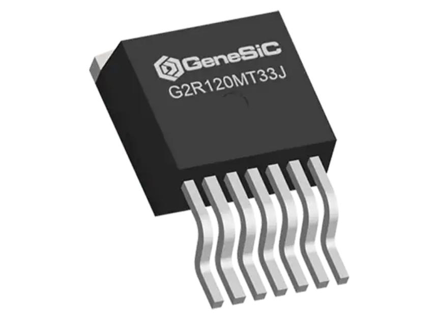
GeneSiC Semiconductor 3300V SiC MOSFETs offer fast and efficient switching with reduced ringing in an optimized package with a separate driver source pin. The 3300V SiC MOSFETs are designed to be compatible with commercial gate drivers and provide ease of paralleling without a thermal runaway. The 3300V SiC MOSFETs deliver low conduction losses at all temperatures, allowing superior robustness and system reliability.

Features

  • Softer RDS(ON) v/s temperature dependency
  • LoRing™ – electromagnetically optimized design
  • Smaller RG(INT) and lower QG
  • Low device capacitances (COSS CRSS)
  • Industry-leading UIL and short-circuit robustness
  • Robust body diode with low VF and low QRR
  • Normally off-stable temperature up to 175°C
  • Optimized package with separate driver source pin

Applications

  • Traction
  • Solar string inverters
  • EV- fast chargers
  • Pulsed power
  • Switched-mode power supply
  • Energy storage
  • Solid-state transformers
  • Solid-state circuit breakers

more information: https://www.genesicsemi.com/sic-mosfet/G2R1000MT33J/G2R1000MT33J.pdf

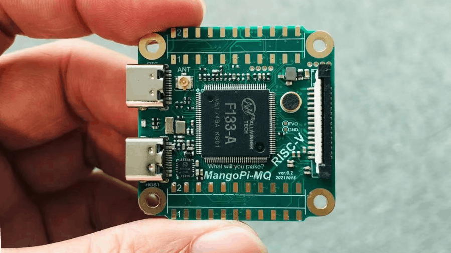
MangoPi-MQ1, a RISC-V Linux Capable Dev Board For Allwinner D1s Is Coming Soon For Under $10

Cost and size are two things you consider when choosing components for portable systems, after functionality and performance. Not too long ago, we saw the Sipeed’s Lichee RV that was launched for about $20 and designed to compete with the $99 Nezha SBC. Now, MangoPi has released an open-source development board called MangoPi-MQ which sells for even a cheaper price of $10.

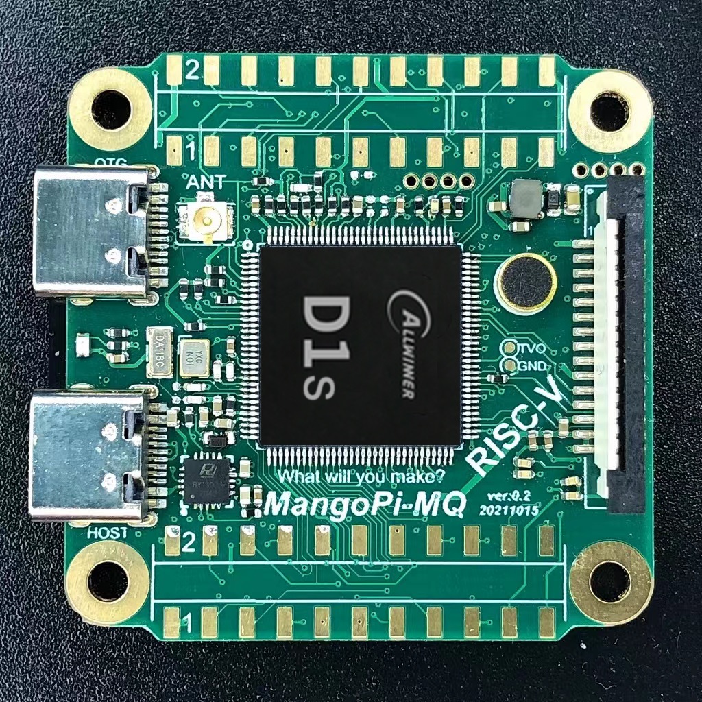
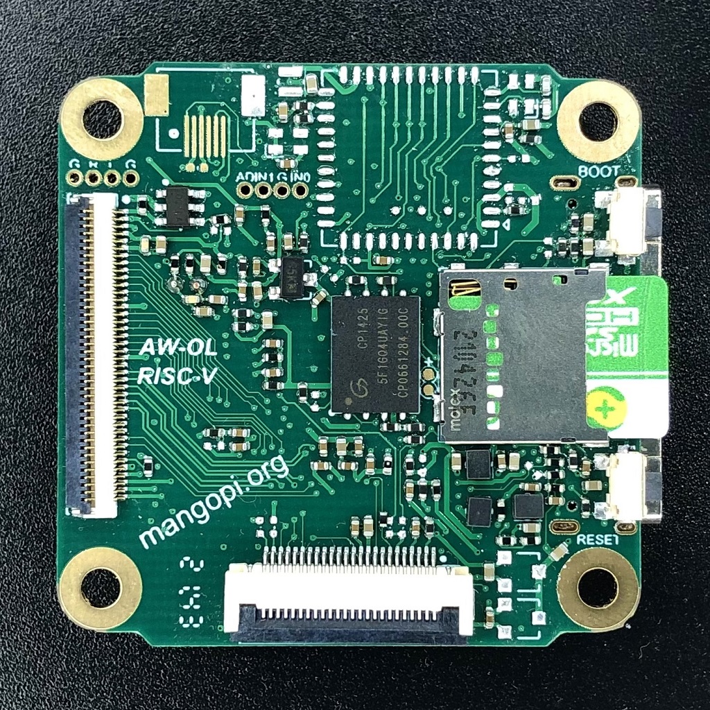
The MangoPi-MQ also called Sparrow is a mini-compact, low-cost and high-performance RISC-V Linux-based development board for Allwinner D1s chip. The development board is a 40mm x 40mm condensed board with minimal resources for reduced systems complexity. It has a clock speed of 1.0 GHz alongside 64MB RAM, and a 5V/2A power supply via OTG or USB-C 2.0 connector. The board also features an LVDS for video support as well as a built-in microphone for audio, WiFi 802.11 b/g/n for networking and micro-SD and SPI NAND for storage.

The D1s SoC is a low-cost chip for Artificial Intelligence of Things (AIoT) for smart packages, signals, and data codec processes. It runs a 64bit RISC-V XuanTie-C906 processor of Alibaba T-Head division with 64MB DDR2, and features audio and video coding and decoding protocols which support H.264, H.265, MPEG-1/2/4, JPEG video formats and ADC/DAC/I2S/PCM/DMIC/OWA audio interfaces. The D1s chipset is Linux compatible and suitable for automotive applications and smart home and industrial solutions.

Key Features and Specifications:

  • SoC: D1s @ 1.0Ghz, 64MB DRAM
  • DC 5V/2A (via OTG or USB-C connector)
  • LVDS
  • Inbuilt microphone, I2S
  • WiFi 802.11 b/g/n
  • Micro-SD
  • SPI NAND
  • 1x USB-C 2.0 Host
  • 1 x USB-C OTG
  • 15P universal Raspberry Pi DSI FPC row seat
  • 40P universal row seat (RGB FPC)
  • 6P universal capacitive touch row seat (FPC)
  • 24 Pin DVP interface
  • 2x 22 Pin extension header
  • Boot button
  • Reset button
  • Dimension: 40 mm x 40mm

MangoPi is open-sourced and Linux systems compatible. According to a preliminary post on hackster, the board will offer a port of Allwinner’s Tina-Linux, more like an old version of OpenWrt framework for resource-constrained environments when sales begin. However, an updated GitHub repository of MangoPi SBC reveals only a license for MangoPi-MQ although the xfel tool for FEL mode of Allwinner’s D1 also supports the D1s according to Linux-Sunxi is available. Other documentation would likely show up on the GitHub repository in due time; you just have to keep following it.

We should expect sales sometime within the month as no fixed date has been made known to the public yet. A post on mangopi.org only just said that the flagship AI-Linux open-source hardware will come soon. The completed boards will likely be available for sale on SeeedStudio and Taobao when sales commence.

Other useful details about the board can be found on the MangoPi website and the product page.

Create BLE project with STM32 and BleuIO

1. Introduction

The project is a simple example showcasing a quick way to set up a STM32Cube project as a USB CDC Host capable of communicating with the BleuIO Dongle.

When a BleuIO Dongle is connected to the Nucleo boards USB port the STM32 will recognize it. It will then accept 3 different inputs from the UART and send one of 3 preprogrammed commands to the BleuIO Dongle based on the input.

The commands that are used in this example are:

  • ATI(Dongle Information)
  • AT+ADVSTART(Starts Advertising)
  • AT+ADVSTOP(Stops Advertising)

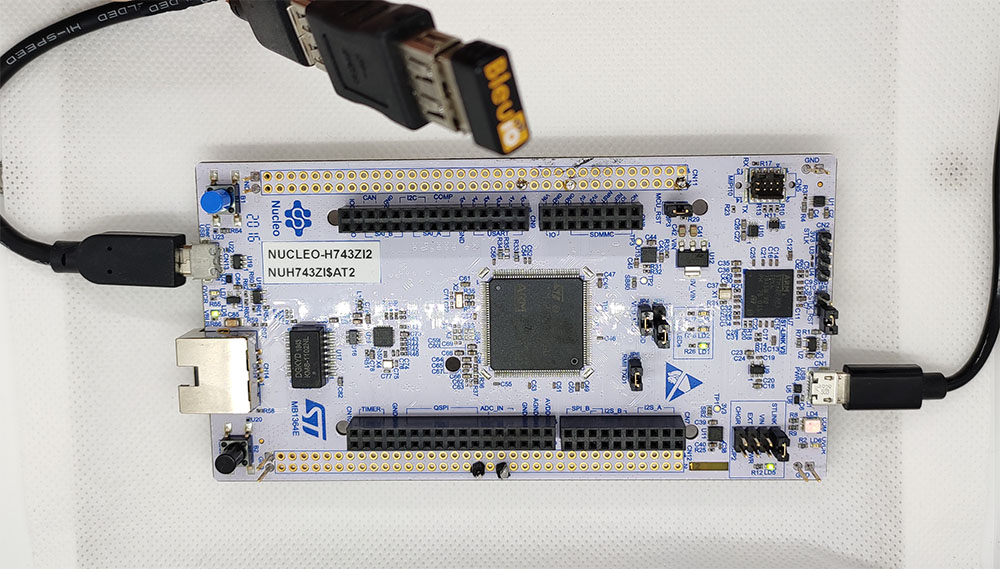
We have used an STM32 Nucleo-144 development board with STM32H743ZI MCU (STM32H743ZI micro mbed-Enabled Development Nucleo-144 series ARM® Cortex®-M7 MCU 32-Bit Embedded Evaluation Board) for this example.

If you want to use another setup you will have to make sure it supports USB Host and beware that the GPIO setup might be different and may need to be reconfigured in the .ioc file.

2. About the Code

You can get the project HERE

https://github.com/smart-sensor-devices-ab/stm32_bleuio_example

This project-based on a new STM32 project with these changes in the .ioc file:

Under ‘Connectivity’ the ‘USB_OTG_FS’-mode is changed to Host_Only and in the NVIC Settings all global interrupts are enabled
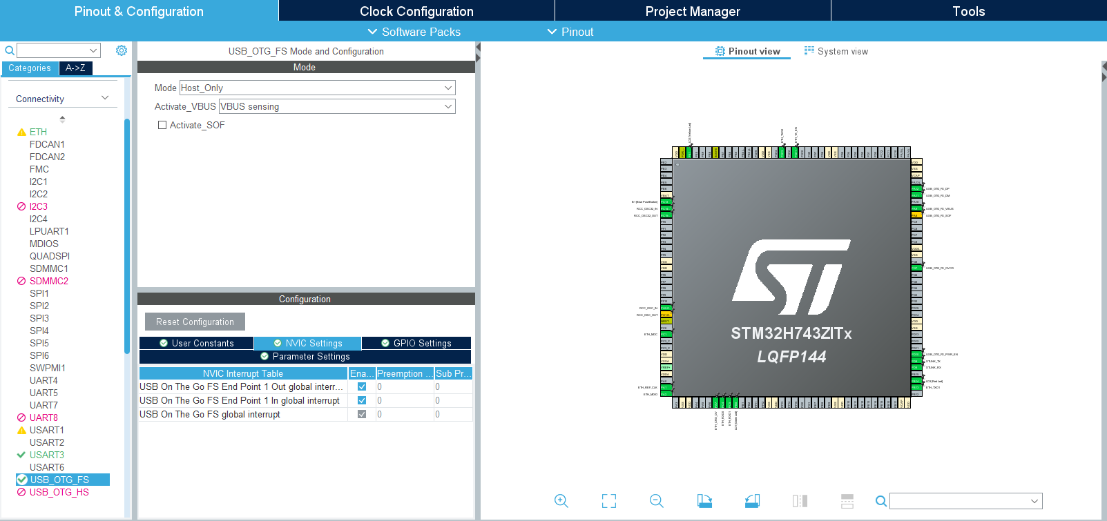
And under ‘Middleware’ the ‘USB_HOST’- ‘Class for FS IP’ is set to ‘Communication Host Class (Virtual Port Com)’.
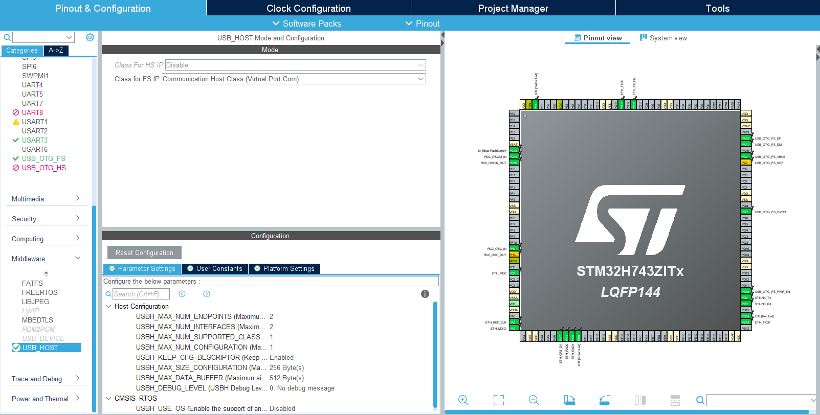
To make sure the host would recognize when the bootloader is done and the BleuIO firmware is running this was added in the USBH_UserProcess function in ‘usb_host.c’ (found under ‘USB_HOST’ -> ‘App’ folder):

static void USBH_UserProcess  (USBH_HandleTypeDef *phost, uint8_t id)
{
  /* USER CODE BEGIN CALL_BACK_1 */
  switch(id)
  {
  case HOST_USER_SELECT_CONFIGURATION:
  break;

  case HOST_USER_DISCONNECTION:
  Appli_state = APPLICATION_DISCONNECT;
  isBleuIOReady = false;

  // Turn on Red LED, turn off Green and Yellow LED
  HAL_GPIO_WritePin(GPIOB, GPIO_PIN_0, GPIO_PIN_RESET);
  HAL_GPIO_WritePin(GPIOE, GPIO_PIN_1, GPIO_PIN_RESET);
  HAL_GPIO_WritePin(GPIOB, GPIO_PIN_14, GPIO_PIN_SET);
  break;

  case HOST_USER_CLASS_ACTIVE:
  Appli_state = APPLICATION_READY;
  // Check if BleuIO firmware is running
  // (idProduct:0x6001 = bootloader, idProduct:0x6002 = bleuio fw)
  if(phost->device.DevDesc.idProduct == 0x6002)
  {
      isBleuIOReady = true;
      // Sends message to uart that BleuIO is connected and ready
      HAL_UART_Transmit(&huart3, (uint8_t*)BLEUIO_READY, strlen(BLEUIO_READY), HAL_MAX_DELAY);

      // Turn on Green LED, turn off Yellow and Red LED
      HAL_GPIO_WritePin(GPIOB, GPIO_PIN_0, GPIO_PIN_SET);
      HAL_GPIO_WritePin(GPIOE, GPIO_PIN_1, GPIO_PIN_RESET);
      HAL_GPIO_WritePin(GPIOB, GPIO_PIN_14, GPIO_PIN_RESET);

      // Start receiving from usb
      USBH_CDC_Receive(&hUsbHostFS, CDC_RX_Buffer, RX_BUFF_SIZE);
  }
  break;

  case HOST_USER_CONNECTION:
  Appli_state = APPLICATION_START;
  isBleuIOReady = false;
  // Turn on Yellow LED, turn off Green and Red LED
  HAL_GPIO_WritePin(GPIOB, GPIO_PIN_0, GPIO_PIN_RESET);
  HAL_GPIO_WritePin(GPIOE, GPIO_PIN_1, GPIO_PIN_SET);
  HAL_GPIO_WritePin(GPIOB, GPIO_PIN_14, GPIO_PIN_RESET);
  break;

  default:
  break;
  }
  /* USER CODE END CALL_BACK_1 */
}

The Green, Red and Yellow LEDs on the Nucleo board are also setup to change based on the connection status.

  • Red = Disconnnected
  • Yellow = Connecting
  • Green = Connected

An external variable bool isBleuIOReady is also set so the status of the dongle is accessible from main.c.

Once the BleuIO dongle is confirmed to be connected the USBH_CDC_Receive function is run to start receiving data from the USB CDC.

The USBH_CDC_ReceiveCallback also needs to be implemented:

void USBH_CDC_ReceiveCallback(USBH_HandleTypeDef *phost)
{
    if(phost == &hUsbHostFS)
    {
        // Handles the data recived from the USB CDC host, here just printing it out to UART
        rx_size = USBH_CDC_GetLastReceivedDataSize(phost);
        HAL_UART_Transmit(&huart3, CDC_RX_Buffer, rx_size, HAL_MAX_DELAY);

        // Reset buffer and restart the callback function to receive more data
        memset(CDC_RX_Buffer,0,RX_BUFF_SIZE);
        USBH_CDC_Receive(phost, CDC_RX_Buffer, RX_BUFF_SIZE);
    }

    return;
}

In this example, the received data is just echoed to the UART.

To send data to the Dongle the USBH_CDC_Transmit function is used. In this example, UART input is used to send different commands.

For this purpose, a wrapper function has been created that can be accessed from main.c:

/**
  * @brief Simple function that takes a string and transmit it to the dongle
  * @retval None
  */
void writeToDongle(uint8_t * cmd)
{
    USBH_CDC_Transmit(&hUsbHostFS, cmd, strlen((char *)cmd));
}

In main.c HAL_UART_RxCpltCallback is implemented to receive input from Uart and a simple UART input handler:

void HAL_UART_RxCpltCallback(UART_HandleTypeDef *UartHandle)
{
    if(UartHandle == &huart3)
    {
        RX_value = (int)aRxBuffer[0];
        uartStatus = UART_RX_NONE;

        switch(RX_value)
        {
            case UART_RX_0:
            {
                uartStatus = UART_RX_0;
                break;
            }
            case UART_RX_1:
            {
                uartStatus = UART_RX_1;
                break;
            }
            case UART_RX_2:
            {
                uartStatus = UART_RX_2;
                break;
            }
            default:
            {
                uartStatus = UART_RX_NONE;
                break;
            }
        }
        // Resets uart recieve interrupt mode
        HAL_UART_Receive_IT(&huart3, (uint8_t *)aRxBuffer, RXBUFFERSIZE);
    }
}


/**
  * @brief Simple uart input handler
  * @retval None
  */
void handleUartInput(UARTCommandTypeDef cmd)
{
    switch(cmd)
    {
        case UART_RX_0:
        {
            // 0
            uart_buf_len = sprintf(uart_tx_buf, "\r\n(0 pressed)\r\n");
            HAL_UART_Transmit(&huart3, (uint8_t *)uart_tx_buf, uart_buf_len, HAL_MAX_DELAY);
            if(isBleuIOReady)
            {
                writeToDongle((uint8_t*)DONGLE_CMD_ATI);
            } else
            {
                uart_buf_len = sprintf(uart_tx_buf, BLEUIO_NOT_READY_MSG);
                HAL_UART_Transmit(&huart3, (uint8_t *)uart_tx_buf, uart_buf_len, HAL_MAX_DELAY);
            }
            uartStatus = UART_RX_NONE;
            break;
        }
        case UART_RX_1:
        {
            // 1
            uart_buf_len = sprintf(uart_tx_buf, "\r\n(1 pressed)\r\n");
            HAL_UART_Transmit(&huart3, (uint8_t *)uart_tx_buf, uart_buf_len, HAL_MAX_DELAY);
            if(isBleuIOReady)
            {
                writeToDongle((uint8_t*)DONGLE_CMD_AT_ADVSTART);
            } else
            {
                uart_buf_len = sprintf(uart_tx_buf, BLEUIO_NOT_READY_MSG);
                HAL_UART_Transmit(&huart3, (uint8_t *)uart_tx_buf, uart_buf_len, HAL_MAX_DELAY);
            }
            uartStatus = UART_RX_NONE;
            break;
        }
        case UART_RX_2:
        {
            // 2
            uart_buf_len = sprintf(uart_tx_buf, "\r\n(2 pressed)\r\n");
            HAL_UART_Transmit(&huart3, (uint8_t *)uart_tx_buf, uart_buf_len, HAL_MAX_DELAY);
            if(isBleuIOReady)
            {
                writeToDongle((uint8_t*)DONGLE_CMD_AT_ADVSTOP);
            } else
            {
                uart_buf_len = sprintf(uart_tx_buf, BLEUIO_NOT_READY_MSG);
                HAL_UART_Transmit(&huart3, (uint8_t *)uart_tx_buf, uart_buf_len, HAL_MAX_DELAY);
            }
            uartStatus = UART_RX_NONE;
            break;
        }
        case UART_RX_NONE:
        {
            break;
        }
        default:
        {
            uartStatus = UART_RX_NONE;
            break;
        }
    }
}

The handleUartInput() handles the inputs 0, 1 and 2 and maps each to a certain Dongle commands. The handler is then put inside the main loop.

/* Infinite loop */
  /* USER CODE BEGIN WHILE */
  while (1)
  {
    /* USER CODE END WHILE */
    MX_USB_HOST_Process();
    /* USER CODE BEGIN 3 */
    // Simple handler for uart input
    handleUartInput(uartStatus);
  }
  /* USER CODE END 3 */

3. Using the example project

3.1 What you will need

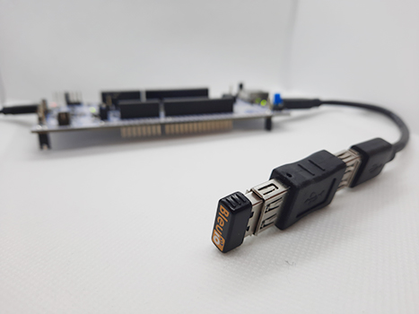
A board with an STM32 Microcontroller with a USB port. (A Nucleo-144 development board: NUCLEO-H743ZI2, was used developing this example. (https://www.st.com/en/evaluation-tools/nucleo-h743zi.html)

To connect the dongle to the Nucleo board a “USB A to Micro USB B”-cable with a USB A female-to-female adapter can be used.)
4. How to setup project

4.1 Downloading the project from GitHub

Get project HERE

https://github.com/smart-sensor-devices-ab/stm32_bleuio_example

Either clone the project or download it as a zip file and unzip it, into your STM32CubeIDE workspace.

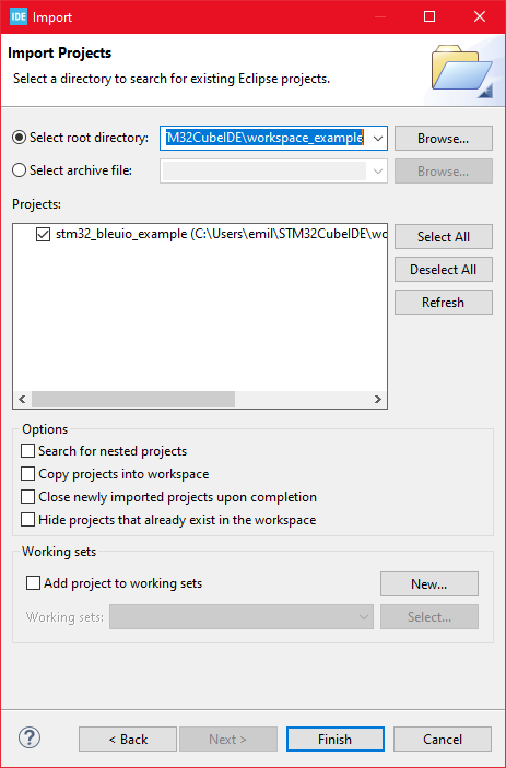
4.2 Importing as an Existing Project

From STM32CubeIDE choose File>Import…

Then choose General>Existing Projects into Workspace then click ‘Next >’
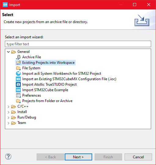
Make sure you’ve choosen your workspace in ‘Select root directory:’

You should see the project “stm32_bleuio_example”, check it and click ‘Finish’.
5. Running the example

  • In STMCubeIDE click the hammer icon to build the project.
  • Open up the ‘STMicroelectronics STLink Viritual COM Port’ with a serial terminal emulation program like TeraTerm, Putty or CoolTerm.Serial port Setup:
    Baudrate: 115200
    Data Bits: 8
    Parity: None
    Stop Bits: 1
    Flow Control: None
  • In STMCubeIDE click the green play button to flash and run it on your board. The first time you click it the ‘Run Configuration’ window will appear. You can just leave it as is and click run.
  • Connect the BleuIO Dongle.
  • Wait until the message: “[BleuIO Dongle Ready]” is shown.

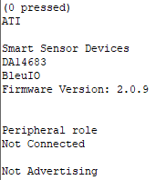
– Press 0 to get device information:
– 1 to start advertising:

– 2 to stop advertising:

Dongle response will be printed to UART.

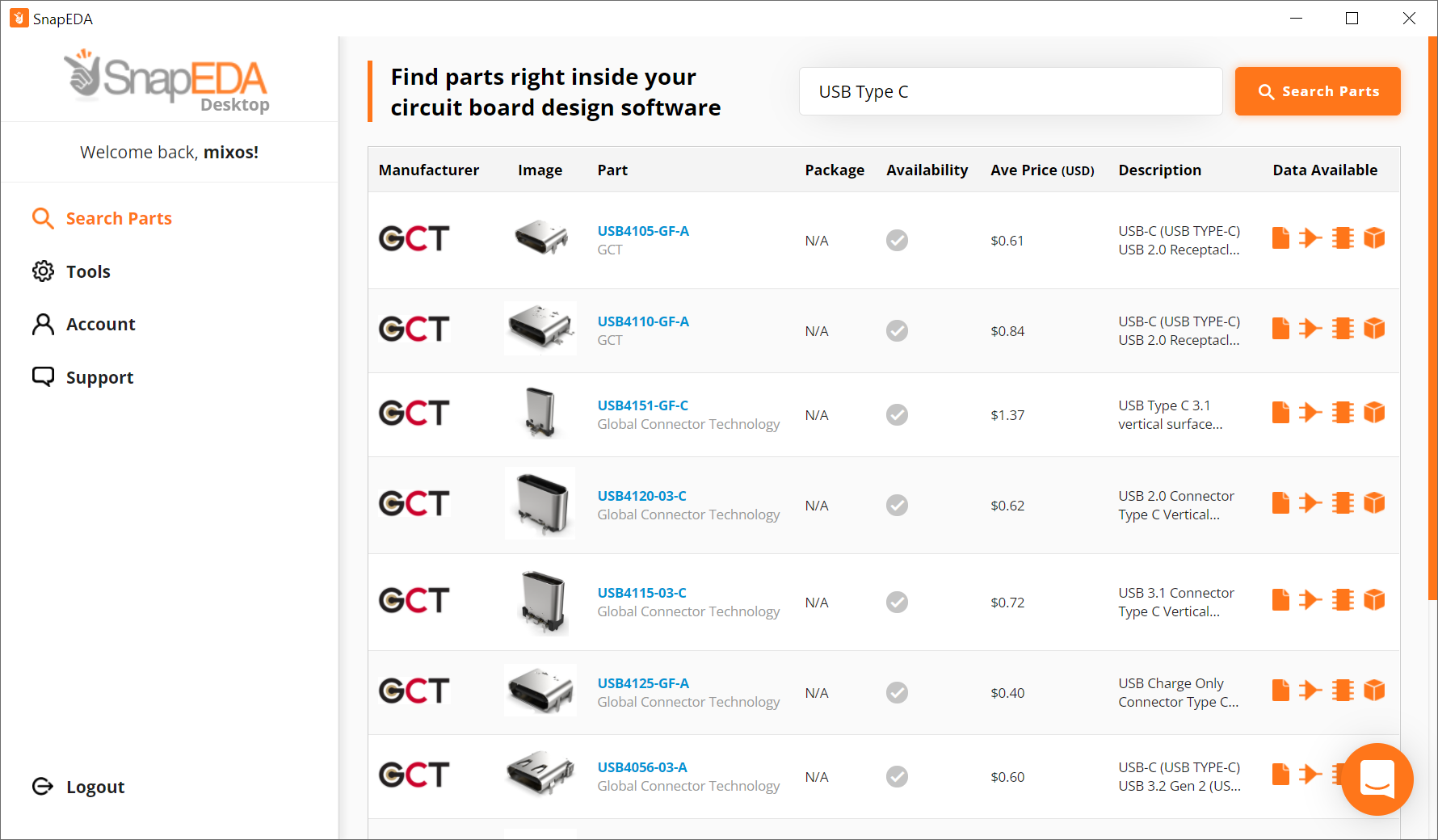
SnapEDA Desktop App is now available for Windows

What is the SnapEDA Desktop App?

SnapEDA mission is to help engineers build products faster by removing design barriers.

This is why they created the SnapEDA Desktop App.

It allows our engineers to place parts seamlessly into their CAD tools in a Snap.

DOWNLOAD THE APP

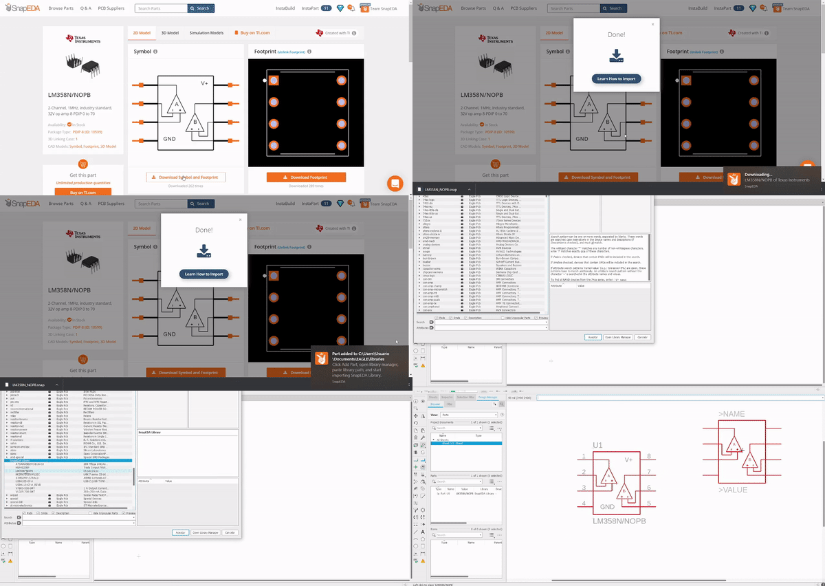
Follow these steps to install the app on Windows:

  1. Extract the downloaded SnapEDA Setup.zip file.
  2. Go to the extracted folder and double-click the SnapEDA Setup.exe to start the installation.
  3. After the installation, you can now use the SnapEDA Desktop App.

Next, find 5 useful articles on how to use this app:

NOTE: They are still optimizing the Mac and Linux versions.

Access BLE data remotely

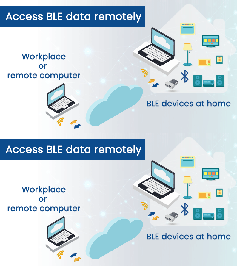
Suppose you have some BLE devices at your home and want to control or scan for those devices while at your workplace. In this project, we will discuss how to access BLE data remotely.

We have already created a script that communicates through BleuIO dongle remotely and gives us the response. You can access the script at: https://github.com/smart-sensor-devices-ab/bledata_remote_access.git

You are free to clone the script and make changes as you wish.

In this script, JavaScript is used to connect to the dongle using google chrome’s serial port. There is a simple PHP script that helps pass data through the cloud.

Step 1: Uploading

Upload the API folder in any server that supports PHP. This script reads and writes data to a JSON file upon request.

We have uploaded the file at http://smartsensor.io/api/api.php

You can use this URL if you don’t have a server to upload.

Step 2: Home computer setup

Open the index.js file found in the root folder and update the URL of the API file on both occasions.

You can leave the url as it is if you want to use file from our server.

Now connect a BleuIO dongle to your home computer and open the index.html file from the root folder.

Click connect and select the COM port where the dongle is connected.

Step 3: Office / Workplace / remote computer setup

Open the index.html file found in the user folder and update the URL of the API file on both occasions.

You can leave the url as it is if you want to use file from our server.

Now open this file in a browser and start writing AT commands.

Currently, You can access the following AT commands

  • ATI (Returns firmware version, hardware type and unique organization identifier, device connection status )
  • AT+CENTRAL (Sets the device Bluetooth role to central role.)
  • AT+PERIPHERAL (Sets the device Bluetooth role to the peripheral.)
  • AT+DUAL (Sets the device Bluetooth role to dual role. Which means it has both Central and Peripheral role capabilities.)
  • AT+ADVSTART (Starts advertising)
  • AT+ADVSTOP (Stops advertising. Returns ERROR if not already advertising)
  • AT+GAPSTATUS (Reports the Bluetooth role)
  • AT+GAPSCAN=2 (Starts a Bluetooth device scan with the timer set in seconds. Make sure to set a timer for the scan.)

Once you type one of the above commands, you will start to see the response from the dongle on your browser screen.

I am trying to scan for BLE devices at my home where BleuIO dongle is connected. Here I got a list of devices showing on my browser screen. Make sure the device is on central mode to scan for devices.

You can add more AT commands to the script as required. All you need to do is update the index.js file found in the root folder.

Find the list of AT commands our from getting started guide at: https://www.bleuio.com/getting_started/docs/commands/

COM-TGUC6: Compact Solution with 11th Generation Intel® Core™ Processors

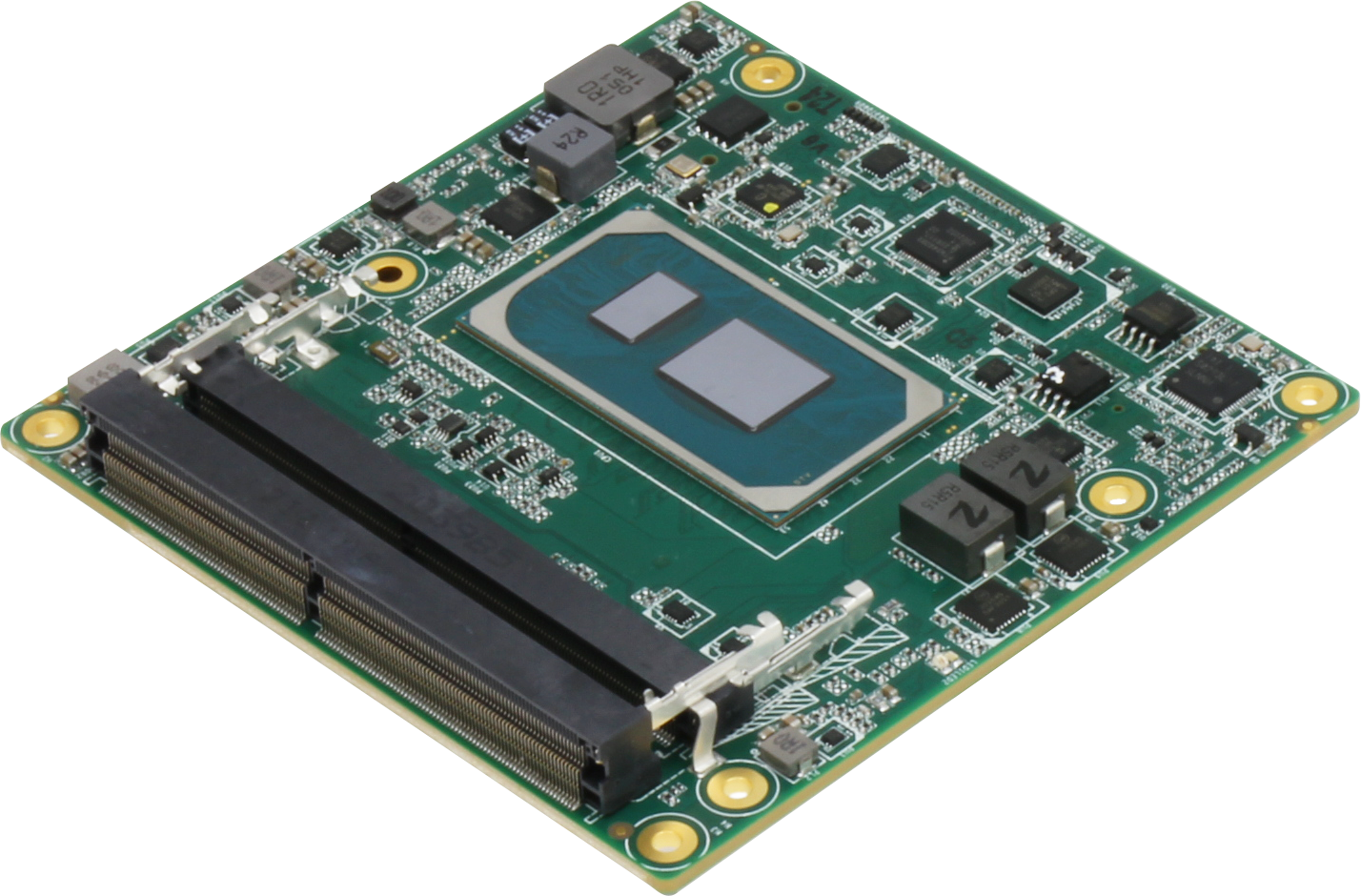
AAEON, a leader in embedded computing solutions, announces the COM-TGUC6, their latest COM Type 6 board, featuring the 11th Generation Intel® Core™ processor. The COM-TGUC6 offers developers and users a significant increase in performance over previous generations of COM boards, with faster memory speeds, greater display support, and higher bandwidth connections. The COM-TGUC6 also delivers a rugged design to work wherever it’s needed.

The COM-TGUC6 brings greater processing performance to embedded computing than before. Along with the 11th Generation Intel Core U processors (formerly Tiger Lake), the COM-TGUC6 delivers faster memory, supporting dual DDR4 modules up to 3200 MHz. The COM-TGUC6 supports in-band ECC, providing memory error detection even with non-ECC memory modules. Together this offers faster, more accurate data processing, vital for increasingly complex applications in robotics and AI computing. Additionally, the COM-TGUC6 can be configured with the industrial grade Intel Core U SKUs, enabling the board to meet WiTAS II wide temperature specifications, providing operation in temperatures from -40°C up to 85°C.

Features

  • 11th Generation Intel® Core™ Processor Family (formerly Tiger Lake UP3)
  • 2 x SODIMM DDR4 3200MHz Memory, up to 32GB (in-band ECC)
  • Intel I225LM Gigabit Ethernet x 1
  • VGA, 18/24-bit 2ch LVDS/eDP, DDI x 3
  • High Definition Audio Interface
  • SATA3.0 x 2
  • USB 2.0 x 8, USB 3.2/2.0 x 4 (up to USB 3.2 Gen 2 support)
  • PCI-Express [x1] x 5 (Gen3), PEG [x4] x1 (Gen4)
  • 12V DC input
  • COM Express Type 6, Compact size, 95mm x 95mm

The COM-TGUC6 is designed to bring faster data processing and connections, utilizing the latest generation of I/O and expansion features. One key feature is the Intel® i225LM chipset, powering 2.5 Gbps Ethernet speeds. This enables faster network connections for applications that demand higher bandwidths. Additionally, the system supports four USB3.2 Gen 2 ports, up to eight USB2.0 ports, as well as SATA III storage devices.

The COM-TGUC6 also provides flexible display support, with connections for VGA, up to three DDI ports, and LVDS/eDP support. The board is capable of powering up to four independent displays, perfect for digital signage, medical equipment and gaming. The COM-TGUC6 also supports a range of expansion options including five PCIe Gen 3 lanes, as well as PCI Express Graphics (PEG) Gen 4 [x4].

AAEON provides customers and clients with a range of services to help ensure the right product for the job. From carrier boards and enclosures to OEM/ODM services, AAEON’s industry-leading service and support helps accelerate development and reduce time to market.

more information: https://www.aaeon.com/en/p/com-express-cpu-modules-com-tguc6

TOP PCB Companies