Compact Raspberry Pi 3 Mini Features High Computing Capabilities

Raspberry Pi 3 Mini

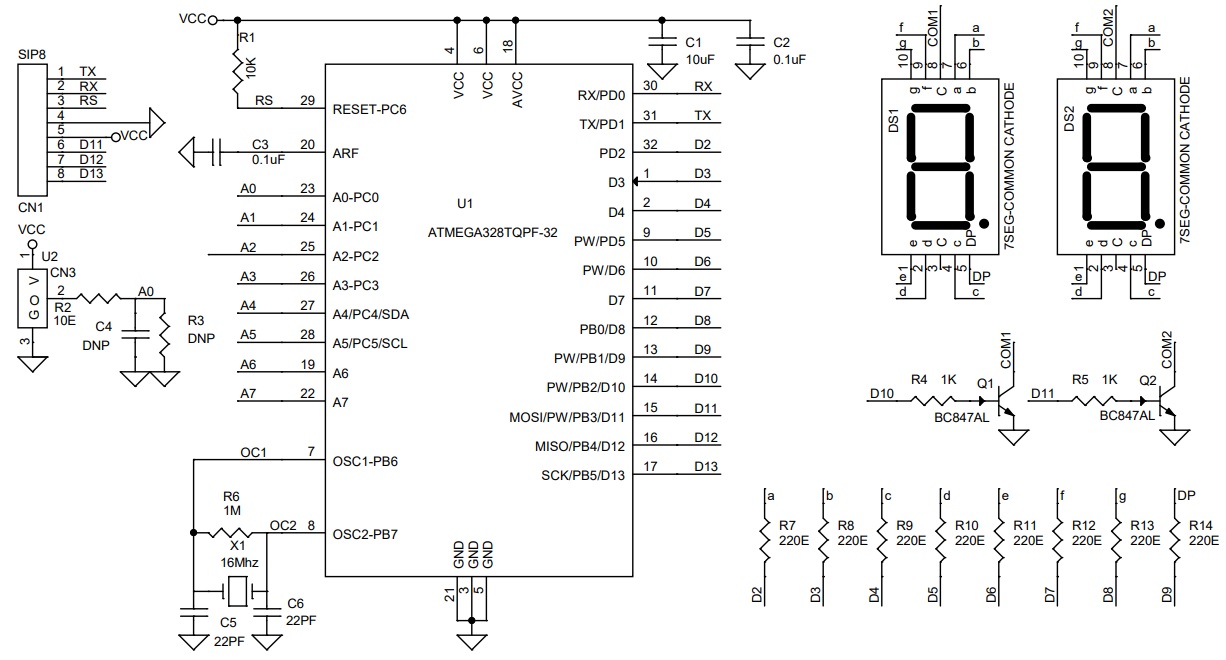
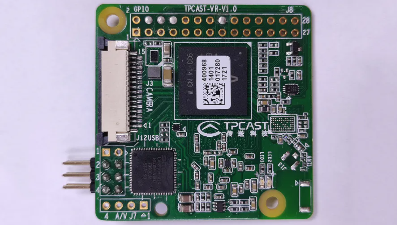
Raspberry Pi SBCs are among the most popular development boards on the market today. Raspberry Pi is available in a variety of flavors, including the Raspberry Pi 2, 3, and 4, as well as the Raspberry Pi Zero boards. Initially, the Raspberry Pi 3 Board was housed in the TPCast-VR, a wireless Adapter for HTC Vive and Oculus Rift VR headsets. However, it paved its way into other applications, like FPV drones.

The new “Raspberry Pi 3 Mini” is not officially a Raspberry Pi board. Instead, it’s a customized Raspberry Pi variant with a small footprint akin to the Raspberry Pi Zero and computing capabilities comparable to the Raspberry Pi 3B. For video streaming applications, the Raspberry Pi 3 Mini seems to be the perfect option.

Raspberry Pi 3 Mini Back

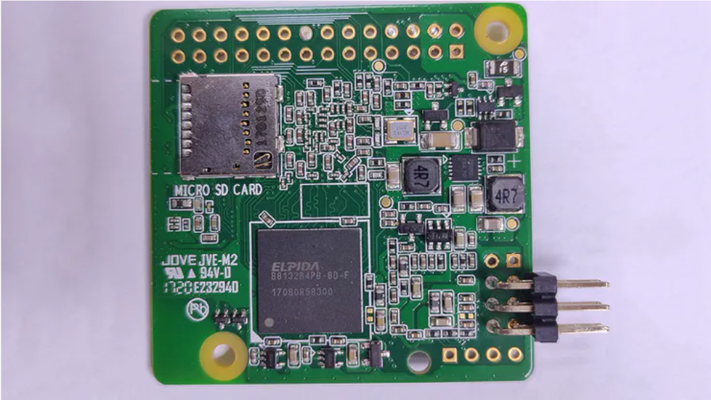
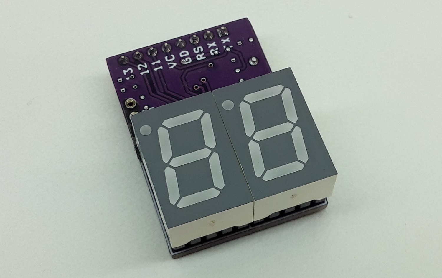
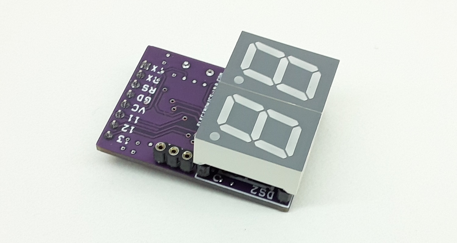
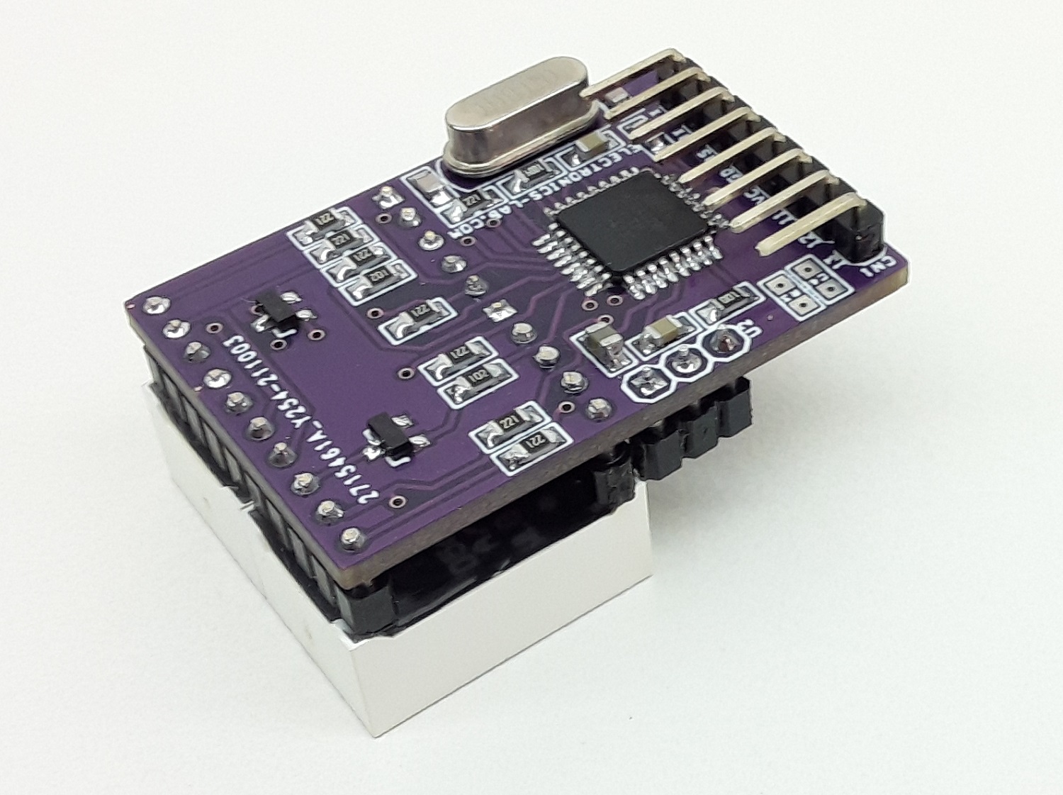
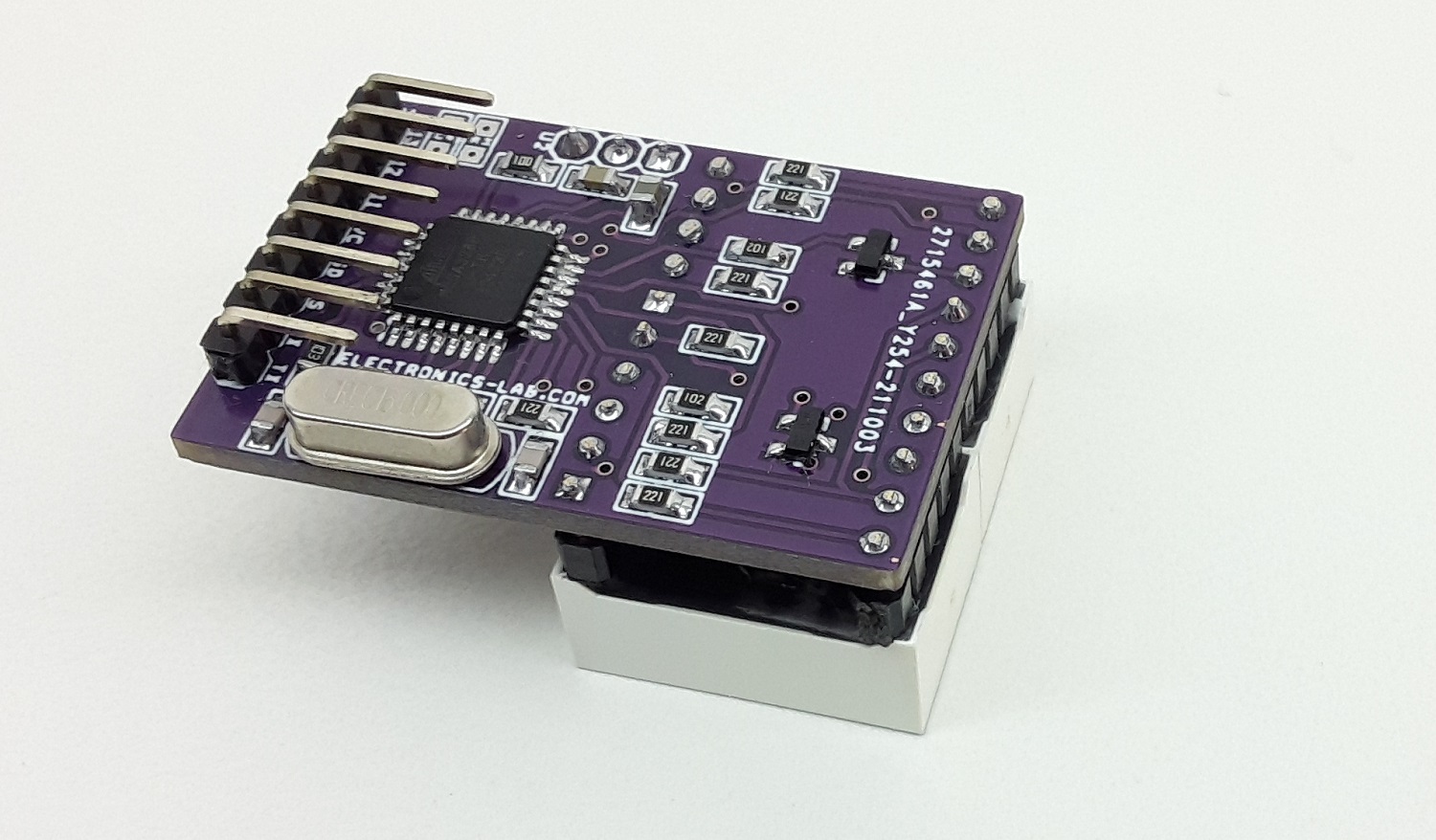
The TPCast board is only 2×2 inches (5 x 5cm) in size and does not have the architecture of a standard Raspberry Pi board. The BCM2837 is the Broadcom chip used in the Raspberry Pi 3, and later models of the Raspberry Pi 2. The chip features a quad-core Arm Cortex-A53 processor, which operates at speeds up to 1.2GHz with Videocore IV GPU. Hence, this makes the device about 50% faster than the Raspberry Pi 2.

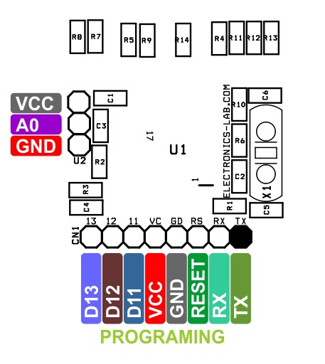
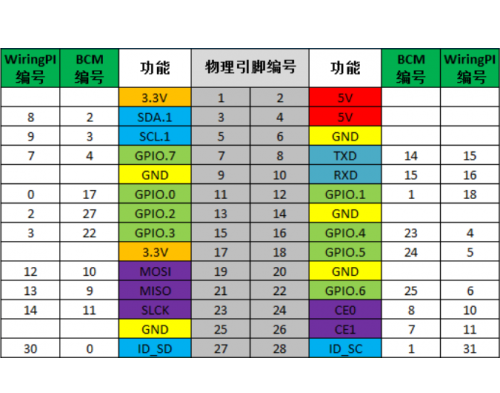
The board comes with a microSD card slot for memory storage and 1GB RAM of system memory. Moreover, a smaller 28-pin variant replaces the standard 40-pin GPIO header. This is a little bigger than the 26-pin version that came with the first Raspberry Pi.

Pinout Diagram of Raspberry Pi 3 Mini

Pinout of Raspberry Pi 3 Mini

Tom’s Hardware post has brought to our attention that, for power, there is no micro USB port; instead, the GPIO provides 5V and GND. As a result, the VR headset to which it is connected must include voltage regulation. There are no USB ports, HDMI connectors, or wireless interfaces, however, there is a four-pin AV port for composite video and stereo audio. Additionally, the hardware also comes with a CSI connector for Raspberry Pi cameras, and two USB 2.0 interfaces through a J12 header. Users have been utilizing this board with OpenHD open-source platform as a more powerful alternative to Raspberry Pi Zero since the FPV community discovered it.

As first spotted by CNX Software, the Raspberry Pi 3 Mini is available on FatBoyFPV at $24.99. For more information visit the product page. Images and technical specifications have also been taken from the product page.

M5Stack UnitV2 M12 Version with Cameras at $95

M5Stack UnitV2 M12 Version with Cameras

M5Stack has been on the market for a long time designing edge computing and IoT devices. The manufacturer is expanding a range of high-efficiency AI recognition modules to UnitV2. Recently, M5Stack has released the UnitV2 M12 version with a camera that features the Sigmastar SSD202D control core. Specially designed for AI recognition functions, industrial visual recognition classification, and machine vision learning, this hardware comes with a GC2145 1080P colored camera sensor.

At the heart of the module is the SSD202D SoC that features a dual-core cortex-A7 processor running at a clock frequency of 1.2 GHz. It comes with integrated 128MB-DDR3 memory and 512MB NAND flashes with microSD expansion. The key difference between all the existing UnitV2 modules and the M21 version lies in the lens equipment of normal focal length (FOV 85°) and wide-angle focal length (FOV: 150°).

Specifications of M5Stack UnitV2 M21 Version

  • SoC: Sigmastar SSD202D has a dual-core cortex A-7 processor
  • Memory: 128MB-DDR3
  • Storage: 512MB NAND flash
  • Wireless Connectivity: 150 Mbps 2.4GHz IEEE 802.11 b/g/n
  • Camera sensor: 150 Mbps 2.4GHz IEEE 802.11 b/g/n
  • Lens: regular focal length and wide-angle fisheye lens
  • Input power: 5V at 500 mA
  • Peripherals: USB Type-C, UART, TFCard, Button, Microphone, Built-in active cooling fan

M5Stack UnitV2 M12 Version with Cameras Specs

The manufacturer mentions the type of AI function, it is capable of performing and those are QR code, face detection, line tracking, image streaming, classification, color tracking, face recognition, target tracking, shape detection, custom object recognition. With this, it is very obvious that this module is targeting edge computing applications that require faster data processing at the end nodes.

An embedded Linux operating system integrated with rich hardware and software specifications makes it a good choice for AI development right out of the box. According to the operating system used, there are drivers that need to be installed while getting started with the module. Drivers for Windows 10 and macOS are readily available on the M5Stack’s documentation.

For more information on this $95.00 edge computing module, you can consider visiting the official product page.

New SoMs from Rongpin Electronics Features Board-to-Board Connectors and Castellations

The new Rongpin Pro-RK3566/RK3568 boards and RP-RK3566/3568 core boards launched by Rongpin Electronics are definitely amongst the most recent AI accelerator system-on-modules that you will find in the hardware market alongside popular SoMs like Firefly Core-3568J AI Core.

The Pro-RK3566 and the Pro-RK3568 feature four Hiose board-to-board connectors interfaces while the RP-RK3566) and RP-RK3568) core boards feature castellated edges interfaces on all four sides.

Below are the key features and specifications of the modules, though, for some unknown reasons, only the RP-RK3568 model of the RP-RK356x series is on the website at the moment with the specifications you will see later.

Key Specifications for Pro-RK3566 and Pro-RK3568 Boards:

  • Rockchip RK3566/RK3568 quad-core Cortex-A55 processor @ 2.0 GHz + Arm Mali-G52 2EE GPU + (support for OpenGL ES 1.1/2.0/3.2, OpenCL 2.0, Vulkan 1.1, 0.8 TOPS NPU for AI acceleration, 4Kp60 H.265/H.264/VP9 video decoding, and 1080p100 H.265/H.264 video encoding)
  • 2GB DDR4 (4GB optional)
  • 8GB eMMC 5.1 flash (optional 16GB to 128GB)
  • Power
    • Pro-RK3566: 3.3V/2A+
    • Pro-RK3568: 3.3V/3A +
    • RockchipRK809-5 PMIC with charge detection and support for lithium battery
  • 4x Hirose board-to-board connectors with:
    • SATA 3.0
    • Pro-RK3568 adds an extra SATA 2.0
    • 1 x HDMI, 1x 4-lane eDP, LVDS, 1 x 8-lane MIPI DSI
    • Pro-RK3568 adds a 24-bit RGB LCD interface
    • 16-bit DVP interface, 2-lane MIPI CSI @ 8MP
    • 2x I2S (1×8 channels,1 x 2 channels); 2x analogue audio inputs, headphone output, mono speaker (0.6W)
    • 1x Gigabit Ethernet (Pro-RK3566)
    • 2x Gigabit Ethernet (Pro-RK3568)
    • 1x USB 3.0
    • 4x USB 2.0 (1 x OTG inclusive)
    • ExtraUSB 3.0 interface for Pro-RK3568
    • PCIe: Pro-RK3566: 1x PCIe 2.0 interface; Pro-RK3568: 1x PCIe 3.0 (two 3.0) and 1x PCIe 2.0
    • 3x SDIO for WiFi, MicroSD card on carrier board
    • 4-channel analogue inputs (Pro-RK3566)
    • 8-channel analogue inputs (Pro-RK3568)
    • Low-speed I/Os: Pro-RK3566 has 8x UART, 3x SPI, 4x I2C, 16x PWM, 98 GPIOs; Pro-RK3568 has 10x UART, 3x SPI, 4x I2C, 15x PWM, 130 GPIOs
  • 5 years + life span with continuous operation
  • Temperature Range
    • Operating: -25 – 75 °C
    • Storage: -30 – 100 °C
  • Dimensions: 60 mm x 40 mm x 4.2mm

The board supports Ubuntu, Android 11, Linux 4.19 + QT 5.12 images. The Company offers development boards with two different carrier boards – PRO-RK3566-B and PRO-RK3568-B.

RP-RK3568 Core Board Specifications:

  • Rockchip RK3568 quad-core Cortex-A55 processor @ 2.0 GHz + Arm Mali-G52 2EE GPU +  (support for OpenGL ES 1.1/2.0/3.2, OpenCL 2.0, Vulkan 1.1, 0.8 TOPS NPU for AI acceleration, 4Kp60 H.265/H.264/VP9 video decoding, and 1080p100 H.265/H.264 video encoding)
  • 2GB DDR4 (optional 4GB/8GB RAM)
  • 8GB eMMC 5.1 flash (optional 16GB to 128GB)
  • 3.3V/3A + power supply
  • Rockchip RK809-5 PMIC with charge detection and support for lithium battery
  • Castellated edges on all four sides with:
    • 1x SATA 3.0, 1x SATA 2.0
    • 1x HDMI, 1x 4-lane eDP, single-channel LVDS, 1× 4-lane MIPI DSI,1x 24-bit RGB LCD interface
    • 1x 16-bit DVP interface, 1x 2-lane MIPI CSI (8MP)
    • 2x I2S (1x 8 channels, 1x 2 channels); 2x analogue audio inputs, headphone output, mono speaker (0.6W)
    • 2x Gigabit Ethernet
    • 2x USB 3.0, 4x USB 2.0 (1x OTG inclusive)
    • PCIe 2.0
    • 3x SDIO for WiFi, MicroSD card on carrier board
    • 2x analogue inputs
    • 10x UART, 3x SPI, 4x I2C, 15x PWM, 130 GPIOs
  • Temperature Range
    • Operating: -25 ~ 75 °C
    • Storage: -30 ~ 100 °C
  • 5 years + life span with continuous operation
  • Dimensions:  50 mm x 50 mm x 3.2mm

The RP-RK3568 also runs Android 11, Ubuntu and Linux 4.19 + QT 5.12 OS. Rongpin also provides development boards for both RK356x series.

There’s also a metal enclosure for safe and fanless operation. The development boards are available on Taobao at $350.00 for RP-RK3568 and $370.00 for Pro-RK3568.

More information on the boards can be found on the Company’s website.

Invigorate your Inspiration for IoT with LoRa-E5 and FREE Seeed Fusion PCBA Prototypes

BIG NEWS!! To accelerate the development of IoT, Seeed is sponsoring Lora-E5 projects with the Seeed Fusion PCB Assembly Service for all hardware enthusiasts, designers, makers, and engineers around the world!

Explore LoRa-E5 & the Seeed Fusion PCBA Service

STM32WL module LoRa-E5 is the first SoC to combine a LoRa RFIC (SX126X) with an MCU (STM32WLE5JC) embedded on a single module. Designed with low energy but high performance, low cost, and compact applications in mind, the FCC and CE certified LoRa-E5 LoRaWAN® module is ideal for long-distance, ultra-low-power applications such as airport tracking, smart agriculture, smart city, wireless meter reading, sensor networks, wireless communication, and other low-power wide-area IoT scenarios.

Orkhan AmirAslan, a hardware engineer from The Things Network (TTN) recently developed a feather-style breakout board for the LoRa-E5 module, which was manufactured with the Seeed Fusion PCB assembly service, a one-stop-shop for electronics manufacture.

Good ideas need to be discovered, and good projects deserve to be recognized, realized and widely disseminated.

If you have an interesting concept for Lora-E5 and are willing to share it with the community, share it with us and we can help you make it a reality with Seeed Fusion’s one-stop-shop capabilities. Get 2 boards fabricated and assembled completely free with Seeed Fusion’s turnkey PCB Assembly service.

Furthermore, choose all your parts from the PCBA Open Parts Libraries (OPL) and reduce the lead time to as little as 7 working days.

Meanwhile, if you have mass production requirements, we highly recommend taking advantage of the Seeed Fusion PCB Assembly service and get the LoRa-E5 modules for only US$5.90 (40% discount, original price US$9.90).

Take your LoRa-E5 project to the next level!

How to apply:

Each person is limited to two PCBA boards 100% completely FREE for one design, including PCB fabrication, the cost of parts, assembly and shipping. The design must include LoRa-E5.

When preparing the BOM file, just add the Seeed SKU 317990687 or the part number LoRa-E5 to your BOM file. Add the order to the cart then contact our customer support (fusion@seeed.cc) to obtain the corresponding cash coupon for settlement.

By participating in this event, you agree to review your experience with us and allow us to share it and the design with the community on our social media platforms (Facebook, Twitter, blog, etc.). The design does not need to be open-sourced and production files will not be shared with the public (unless you want to). We hope your experience will go onto inspire more users to embrace IoT, LoRaWAN® and its capabilities.

Further Cooperation With Seeed

Seeed can assist designers with an established project plan with product development and mass production. Furthermore, we can assist with sales and distribution using our global sales network, and designers can obtain the licensing fees through sales by becoming a senior partner.

We hope to see more Lora-E5 application cases involving smart agriculture, smart logistics management, smart water meter, smart home and smart parking system, etc. If you have any questions, please feel free to contact our customer support at fusion@seeed.cc for further consultation. We look forward to hearing from you!

Variscite and Hailo Partner to Provide Out-of-the-Box, Full-Scale, Edge AI Solutions

Variscite’s i.MX 8 System on Modules, combined with Hailo’s Mini PCIe AI module, enables enterprises to run full-scale deep learning (DL)-based applications more efficiently and sustainably while significantly lowering costs

Variscite, a leading global provider of trusted Systems on Module (SoM) solutions for the embedded market, today announced its partnership with leading AI (Artificial Intelligence) chipmaker Hailo to launch a ready-to-use reference platform enabling high-performance and scalable AI capabilities at the edge.

The joint, complete edge AI solution will combine Variscite’s i.MX 8 platforms with Hailo’s Mini PCIe AI module to enable enterprises to run full-scale deep learning (DL)-based applications more efficiently and sustainably while significantly lowering their costs.

Variscite’s DART-MX8M-PLUS and VAR-SOM-MX8M-PLUS are based on NXP’s i.MX 8M Plus SoC with integrated AI capabilities up to 2.3 tera-operations per second (TOPS). These products, combined with the Hailo-8TM AI processor , which provides up to 26 TOPS and significantly outperforms other AI edge processors in the market, deliver high-performance, scalable edge AI solutions for industries including Industry 4.0, smart cities, smart retail, automotive and more. Moreover, Hailo’s AI accelerator modules can be mounted on additional Variscite SoM platforms, including processors from the i.MX 8 series that have no integrated AI engine, such as the i.MX 8M and i.MX 8M Mini.

“Our joint partnership with leading AI company such as Hailo allows us to expand access to AI and deep learning at the edge to a wider range of customers and applications, while upgrading our product offering with a higher-performance solution”, said Ofer Austerlitz, VP Business Development and Sales at Variscite.”We are excited to offer our customers advanced AI at the edge solutions, enabling them to power applications across the various industries they are in with a more scalable and higher performance solution”.

Variscite’s System on Modules, integrated with the Hailo’s mPCIe AI module and with the compatible Basler camera,  delivers 30 Frames Per Second (FPS) while running YOLOv5m in Full High Definition (FHD) resolution with minimal power consumption.

“Our partnership with leading SoM vendor Variscite brings the performance capabilities of customers’ edge devices to a new level”, said Liran Bar, VP Business Development of Hailo. “This joint solution significantly boosts the AI capabilities for anyone using Variscite’s System on Modules, enabling a broader range of deep learning-based applications in industries across the board. We look forward to continuing our collaboration with Variscite to help bolster the power of edge devices everywhere.”

The Hailo-8™ Mini PCIe AI acceleration module is fully integrated with Variscite’s i.MX 8 platforms, providing customers with state-of-the-art AI capabilities integrated directly into their connected edge devices.

Arduino 4-Digit 0.5″ Common Cathode 7 Segment Display Module

This project will help you to easily develop an Arduino compatible project that requires 4 x -7Segment 0.5″ displays. The project consists of an Atmega328 microcontroller, 4 x BC847 NPN transistors to drive the common cathode displays. All displays are used in multiplexing configurations. The circuit operates with 5V DC and consumes a few milliamps. Arduino code is provided to test the board. The code is pretty simple, it will read 0 to 5V on analog pin A0 and display 0 to 1000 display, basically 0 to 5V mapping to 0-1000. Users may write their own code to read an analog voltage from a sensor or other source and display it on the 4 x 7segment displays.

The new Atmega328 chip requires a bootloader and Arduino firmware, follow the link below to learn more about programming and bootloader burning.

https://www.arduino.cc/en/Tutorial/BuiltInExamples/ArduinoToBreadboard

Arduino Compatible Hardware Contains

  • Atmega328 microcontroller
  • 4 Digit 0.5″ 7 Segment Display, Common Cathode
  • 4 x BC847 Transistors to drive Display Common Cathode for Multiplexing
  • CN1: Arduino Programming and Boot-Loader
  • CN1: 3 Pin Connector to Connect LM35 Temperature Sensor or Analog Input
  • Current Limiting Resistors for 7 segment display and other components

Applications

  • 4 Digit Counter
  • 4 Digit Thermometer
  • Voltmeter
  • Current Meter
  • Sensor Value Display- Analog Voltage Reading
  • 4 Digit Score Board
  • Gaming

Features

  • Supply 5V DC, can be optimized for 3.3V Operations
  • LM35 Temperature Sensor or Analog Input A0
  • Compact Hardware
  • PCB Dimensions 51.28 x 34.93 mm

Arduino Pins

  • Digital Pin D10 Display 1 Common Cathode
  • Digital Pin D11 Display 2 Common Cathode
  • Digital Pin D12 Display 3 Common Cathode
  • Digital Pin D13 Display 4 Common Cathode
  • Digital Pin D2 Display Segment A
  • Digital Pin D3 Display Segment B
  • Digital Pin D4 Display Segment C
  • Digital Pin D5 Display Segment D
  • Digital Pin D6 Display Segment E
  • Digital Pin D7 Display Segment F
  • Digital Pin D8 Display Segment G
  • Digital Pin D9 Display Segment DP
  • Analog Pin A0 Analog Input from Sensor, LM35 Temperature Sensor

Similar Modules

Schematic

Parts List

NOQNTY.REF.DESCMANUFACTURERSUPPLIERPART NO
11CN13 PIN MALE HEADER PITCH 2.54MMWURTHDIGIKEY732-5316-ND
22C1,C40.1uF/50V SMD SIZE 0805MURATA/YAGEODIGIKEY
32C2,C322PF/50V SMD SIZE 0805MURATA/YAGEODIGIKEY
42C5,R17DNP
54DS1,DS2,DS3,DS40.5/0.56INCH 7 SEGMENT DISPLAY COMMON CATHODELUMEX OPTODIGIKEY
61D1LED SMD SIZE 0805LITE ON INCDIGIKEY160-1427-1-ND
74Q1,Q2,Q3,Q4BC847ALNEXPERIADIGIKEY1727-2924-2-ND
85R1,R4,R5,R6,R71K 5% SMD SIZE 0805MURATA/YAGEODIGIKEY
91R210K 5% SMD SIZE 0805MURATA/YAGEODIGIKEY
101R31M 5% SMD SIZE 0805MURATA/YAGEODIGIKEY
118R8 To R15220E 5% SMD SIZE 0805MURATA/YAGEODIGIKEY
121R1610E 5% SMD SIZE 0805MURATA/YAGEODIGIKEY
131U1ATMEGA328 DIP 28MICROCHIPDIGIKEYATMEGA328-PU-ND
141Y116MHZECS INCDIGIKEYX1103-ND
151CN22 PIN MALE HEADER PITCH 2.54MMWURTHDIGIKEY732-5315-ND
161SCKT28 PIN DIP IC SOCKETON SHORE TECHDIGIKEYED3050-5-ND

Connections

Gerber View

Photos

Video

SC56-21SRWA Datasheet

Arduino 3-Digit 0.5″ Common Cathode 7 Segment Display Module

This project will help you to easily develop an Arduino compatible project that requires 3 x 7-Segment 0.5″ displays. These are common cathode displays that use multiplexed configuration, BC847 transistor drives 3 x common cathodes, all display segments are connected to the microcontroller using current limiting resistors. The circuit operates with 5V DC, Connector CN1 is provided for bootloader and Arduino firmware upload. Upload Arduino code to test the board. The user will be able to create a 5.00V Voltage Meter. Use analog pin A0 for voltage input, Connector U2.

Arduino Programming

A new Atmega328 chip requires a bootloader and Arduino firmware upload. Connector CN1 is provided for both operations, follow the link below to learn more about programming the board using Arduino.

https://www.arduino.cc/en/Tutorial/BuiltInExamples/ArduinoToBreadboard

Arduino Compatible Hardware

  • Atmega328 microcontroller
  • 3 x Digit 0.5 Inch 7 Segment Display, Common Cathode
  • 3 x BC847 Transistors to drive Display Common Cathode for Multiplexing
  • CN1: Arduino Programming and Boot-Loader
  • U2: 3 Pin Connector to Connect LM35 Temperature Sensor or Analog Input
  • Current Limiting Resistors for 7 segment display and other components

Applications

  • 3 Digit Counter
  • 3 Digit Timer
  • 3 Digit Thermometer
  • Voltmeter
  • Current Meter
  • Sensor Value Display
  • 3 Digit Score Board
  • Dice

Features

  • Supply 5V DC can be optimized for 3.3V Operations
  • LM35 Temperature Sensor or Analog Input A0
  • Compact Hardware
  • PCB Dimensions 38.42 x 35.40 mm

Arduino Pins

  • Digital Pin D10 Display 1 Common Cathode
  • Digital Pin D11 Display 2 Common Cathode
  • Digital Pin D12 Display 3 Common Cathode
  • Digital Pin D2 Display Segment A
  • Digital Pin D3 Display Segment B
  • Digital Pin D4 Display Segment C
  • Digital Pin D5 Display Segment D
  • Digital Pin D6 Display Segment E
  • Digital Pin D7 Display Segment F
  • Digital Pin D8 Display Segment G
  • Digital Pin D9 Display Segment DP
  • Digital Inputs D13, D12, D11, TX, RX (Available for Inputs after programming)
  • Analog A0 for Analog Signal Input from Sensor or Analog Source
  • Programming and Boot-loader Pin D13, D12, D11, TX, RX, RESET

Similar modules

Schematic

Parts List

NOQNTY.REFDESCMANUFACTURERSUPPLIERPART NO
11CN18 PIN MALE HEADER PITCH 2.54MMWURTHDIGIKEY732-5321-ND
21C110uF/10V SMD SIZE 0805MURATA/YAGEODIGIKEY
32C2,C30.1uF/50V SMD SIZE 0805MURATA/YAGEODIGIKEY
42R3,C4DNPMURATA/YAGEODIGIKEY
52C5,C622PF/50V SMD SIZE 0805MURATA/YAGEODIGIKEY
63DS1,DS2,DS30.5/0.56 INCH 7 SEGMENT COMMON CATHODE DISPLAYSUN LEDDIGIKEY754-1705-5-ND or 754-1704-5-ND
73Q1,Q2,Q3BC847ALNEXPERIADIGIKEY1727-2924-2-ND
81R110K 5% SMD SIZE 0805MURATA/YAGEODIGIKEY
91R210E 5% SMD SIZE 0805MURATA/YAGEODIGIKEY
103R4,R5,R61K 5% SMD SIZE 0805MURATA/YAGEODIGIKEY
118R7-R14220E 5% SMD SIZE 0805MURATA/YAGEODIGIKEY
121R151M 5% SMD SIZE 0805MURATA/YAGEODIGIKEY
131U1ATMEGA328TQPF-32MICROCHIPDIGIKEYATMEGA328PB-AURCT-ND
141U23 PIN MALE OR FEMALE HEADER OPTIONAL
151X116MhzECS INCDIGIKEYX1103-ND

Connections

Gerber View

Photos

Video

SC56-21SRWA Datasheet

Arduino 2-Digit 0.5″ Common Cathode 7 Segment Display Module

This is an Arduino compatible board for creating 2 Digit Display projects. The circuit operates with 5V DC, Connector CN1 is provided for bootloader programming and Arduino firmware upload. A new Atmega328 chip requires a bootloader and Arduino firmware programming, Connector CN1 helps you with both functions. Follow the link below to learn more about programming using Arduino. Arduino code is available as a download to test the board.

Arduino Programming

From Arduino to a Microcontroller on a Breadboard: https://www.arduino.cc/en/Tutorial/BuiltInExamples/ArduinoToBreadboard

Arduino Compatible Hardware

  • Atmega328 microcontroller
  • 2 Digit 0.5 Inch 7 Segment Display, Common Cathode
  • 2 x BC847 Transistors to drive Display Common Cathode for Multiplexing
  • CN1: Arduino Programming and Boot-Loader Connector
  • U2: 3 Pin Connector to Connect LM35 Temperature Sensor or Analog Input
  • Current Limiting Resistors for 7 segment display and other components

Applications

  • 2 Digit Counter
  • 2 Digit Timer
  • 2 Digit Thermometer
  • Voltmeter
  • Current Meter
  • Sensor Value Display
  • 2 Digit Score
  • Digital Dice

Arduino Pins

  • Digital Pin D10 Display 1 Common Cathode
  • Digital Pin D11 Display 2 Common Cathode
  • Digital Pin D2 Display Segment A
  • Digital Pin D3 Display Segment B
  • Digital Pin D4 Display Segment C
  • Digital Pin D5 Display Segment D
  • Digital Pin D6 Display Segment E
  • Digital Pin D7 Display Segment F
  • Digital Pin D8 Display Segment G
  • Digital Pin D9 Display Segment DP
  • DIGITAL INPUTS D13, D12, D11, TX, RX
  • ANALOG PIN A0 LM35 TEMPERATURE SENSOR OR ANALOG INPUT
  • PROGRAMING D13, D12, D11, TX, RX, RESET

Features

  • Supply 5V DC can be optimized for 3.3V Operations
  • LM35 Temperature Sensor, Analog Input A0
  • Compact Hardware
  • PCB Dimensions 37.78  x 26.04 mm

Similar modules

Schematic

Parts List

NOQNTY.REF.DESC.MANUFACTURERSUPPLIERPART NO
11CN18 PIN MALE HEADER PITCH 2.54MMWURTH732-5321-ND
21C110uF/10V SMD SIZE 0805MURATA/YAGEO
32C2,C30.1uF/50V SMD SIZE 0805MURATA/YAGEO
42R3,C4DNP
52C5,C622PF/50V SMD SIZE 0805MURATA/YAGEO
61DS17SEG-COMMON CATHODE 0.5INCHSUNLED754-1705-5-ND or 754-1704-5-ND
71DS27SEG-COMMON CATHODE 0.5INCHSUNLED754-1705-5-ND or 754-1704-5-ND
82Q1,Q2BC847ALNEXPERIA1727-2924-2-ND
91R110K 5% SMD SIZE 0805MURATA/YAGEO
101R210E 5% SMD SIZE 0805MURATA/YAGEO
112R4,R51K 5% SMD SIZE 0805MURATA/YAGEO
121R61M 5% SMD SIZE 0805MURATA/YAGEO
138R7 - R14220E 5% SMD SIZE 0805MURATA/YAGEO
141U1ATMEGA328TQPF-32MICROCHIPATMEGA328PB-AURCT-ND
151U23 PIN MALE OR FEMALE HEADER PITCH 2.54MMDNP
161X116MhzECS INCX1103-ND

Connections

Gerber View

Photos

Video

SC56-21SRWA Datasheet

PICO-EHL4: Flexible Embedded Edge Computing from AAEON

AAEON, an industry leader in embedded solutions, announces the latest addition to its lineup of compact PICO-ITX boards, the PICO-EHL4. Featuring the latest Intel® Atom™, Celeron® and Pentium® processors (formerly Elkhart Lake). With the combination of performance, flexibility and expansion features, the PICO-EHL4 provided developers with a capable solution for any project.

The PICO-EHL4 builds upon previous generations by delivering higher performance processors, faster memory speeds, and support for the latest computing technologies. This is thanks to utilizing the latest generation Intel® Atom™ x6000E series processors, Intel Pentium® and Celeron® N and J series processors (formerly Elkhart Lake). The PICO-EHL4 takes advantage of the support for faster memory speeds and higher capacities by providing up to 16GB of LPDDR4x 3200MHz memory on-board. The PICO-EHL4 also leverages support for in-band ECC with select processors, ensuring data integrity, an important feature for edge computing applications.

The PICO-EHL4 provides a host of features allowing for flexibility to meet the needs of individual applications. Expansion slots include both M.2 2230, perfect for adding Wi-Fi or Bluetooth functionality; and full sized Mini-Card for expanded storage, AI accelerators, and more. The PICO-EHL4 can connect with a range of devices thanks to 4-bit GPIO as well as dual Gigabit Ethernet LAN ports, two USB3.2 and two USB2.0 ports, and two serial port headers (RS232/422/485). The PICO-EHL4 also features two HDMI 2.0 ports supporting 4K graphics at 60Hz, as well as on-board co-lay LVDS/eDP allowing the board to output up to three independent displays.

“The PICO-EHL4 delivers greater performance and flexibility than previous generations, at a cost that is comparable, making it a great choice for new projects or upgrading existing deployments without going over budget,” said Ariel Long, Product Manager with AAEON’s Embedded Computing Division. “Developers can easily deploy the board to a range of applications including AI edge computing, compact PC controller, kiosks and more.”

The PICO-EHL4 is backed by AAEON’s expertise in building compact, rugged solutions designed to operate in a wide range of industrial and other environments. AAEON also offers a range of manufacturer and OEM/ODM services, from customizing board layouts to helping developers create a board level solution that fits the requirements of their applications. Customers wanting to learn more about the PICO-EHL4 can visit the AAEON website where they can also get in touch with AAEON representatives.

8A Brushed DC Motor Driver with Adjustable Constant Current, Direction Control, Brake Control, Speed Control

This is a very powerful brushed DC motor drive system in a small package with a few key features like adjustable constant current control, direction control, brake controls, Alert output, PWM for speed control etc. The project was built using a TB67H303HG chip which is a full-bridge driver IC for DC motor adopting MOS at output transistors. High-power and high-efficient drive are possible by adopting DMOS output driver with low-ON resistance and PWM drive. Refer to the datasheet of TB67H303HG for more information.

Features

  • DC Motor 24V DC, (Range 8 to 40V DC)
  • CW/CCW, Short Brake, Stop Function
  • PWM control (Direct PWM or Constant-current PWM drive)
  • Standby Function
  • Load 8.0 A (operating range, maximum value)
  • On-Board Power LED D1
  • PWM Frequency Input Up to 100Khz, Duty Cycle 50%
  • PCB Dimensions 53.98 x 36.83 mm
Note: Large size heatsink with a fan is recommended

The project has been designed for constant current mode however, this can be used as direct PWM mode with a few changes, explained below.

Selection of Constant Current Mode

  • Close The Jumper J3 for standby or Provide 3.3V or 5V to Standby Pin3 (SBY) of CN3
  • Jumper Select J2 Open (Select Pin =High)
  • Jumper J1 Close (Jumper Connects, VREF 5V and Logic Supply) Remove this Jumper for External Micro-Control Interface
  • Trimmer Potentiometer PR1: Adjust the Constant Current (0.3V to 1.95V)
  • CN1 Motor Connection
  • CN2 DC Motor Supply 24V DC (Range 8 to 42V DC)
  • Oscillator R3 51K Ohms provides 40Khz Chopping Frequency (30K Ohms=60Khz, 120K Ohms 20Khz)
  • Alert 1 provides High Signal, Goes Low when ISD or TSD (CN3 Pin 2), ISD=Over Current, TSD=Thermal Shutdown
  • Alert 2 When Motor Supply falls to 6.0V (typ.) and UVLO is enabled, output turns off and ALERT 2 outputs low. In case Motor supply falls below 6.0V (typ.), ALERT 2 outputs Hi-Z (High impedance). The operation returns from Standby mode when Vic rises 6.5V (typ.) or more. (CN3 Pin 7)
  • Apply PWM Signal to PWM Pin 6 of CN3

ISD (Over current detection)

  • Current that flows through output power MOSFETs are monitored individually. If over-current is detected in at least one of the eight output power MOSFETs, all output power MOSFETs are turned off. Masking term of 1μs or more (typ. when Rosc=51kΩ) should be provided in order to protect detection error by noise. ISD does not work during the masking term. The operation is not returned automatically. It is latched. This function is released by programming STBY H→L→H.

Selection Direct PWM mode with few changes

  • Pull Down Select Pin Low by Closing the Jumper J2
  • Replace Shunt Resistor R5 with 0 Ohms or use wire to shorth this resistor
  • Jumper J1 Close (Jumper J1 Short)
  • Pull Down VREF Pin, Do Not Populate R6, R8 0 Ohms, Turn Trimmer Pot to Minimum to zero or short two terminals so VREF pin is connected to GND

The motor rotation speed is controllable by the PWM input sent through the PWM pin 6 CN3. It is also possible to control the motor rotation speed by sending in the PWM signal through not the PWM pin but the IN1 and IN2 pins. When the motor drive is controlled by the PWM input, the TB67H303HG repeats operating in Normal Operation mode and Short Brake mode alternately. For preventing the shoot-through current in the output circuit caused by the upper and lower power transistors being turned on simultaneously, the dead time is internally generated at the time the upper and lower power transistors switch between on and off.  This eliminates the need of inserting Off time externally; thus, the PWM control with synchronous rectification is enabled. Note that inserting Off time externally is not required on operation mode changes between CW and CCW, CW and Short Brake, and CCW and Short Brake because of the dead time generated internally.

Connections CN3

  • Pin 1: LV Logic Supply Connected to VREG 5V Using Jumper J1 (Don’t Use) NC
  • Pin 2: Alert 1 TSD/ISD Normally High, Goes Low when Alert Occurs
  • Pin 3: IN1 Direction Change or Brake Operations (High or Low)
  • Pin 4: IN2 Direction Change or Brake Operations (High or Low)
  • Pin 5: PWM Input 3.3V or 5V TTL Signal (PWM Frequency Up to 100Khz Duty Cycle 50%)
  • Pin6: GND

Arduino UNO Connection

Arduino test code is available as a download below. Please refer to the connection layout below to test the board.

Schematic

Parts List

NOQNTYREF.DESCMANUFACTURERSUPPLIERPART NO
11CN12 PIN SCREW TERMINAL PITCH 5.08MMPHOENIXDIGIKEY277-1247-ND
21CN22 PIN SCREW TERMINAL PITCH 5.08MMPHOENIXDIGIKEY277-1247-ND
31CN38 PIN MALE HEADER PITCH 2.54MMWURTHDIGIKEY732-5321-ND
43C1,C3,C40.1uF/50V SMD SIZE 0805MURATA/YAGEODIGIKEY
51C2470uF/50V RUBYCONDIGIKEY1189-3768-1-ND
61D1LED RED SMD SIZE 0805LITE ON INCDIGIKEY160-1427-1-ND
71J1,J2,J32 PIN MALE HEADER PITCH 2.54MMWURTHDIGIKEY732-5315-ND
83SHTJUMPER SHUNT FOR J1,J2,J3SULINS DIGIKEYS9001-ND
91R210K 5% SMD SIZE 0805MURATA/YAGEODIGIKEY
103R1,R3,R451K 1% SMD SIZE 0805MURATA/YAGEODIGIKEY
111R50.1E/2W SMD SIZE 2512MURATA/YAGEODIGIKEY
121R618K 1% SMD SIZE 0805MURATA/YAGEODIGIKEY
131R74K7 5% SMD SIZE 0805MURATA/YAGEODIGIKEY
141R81.2K 1% SMD SIZE 0805MURATA/YAGEODIGIKEY
151U1TB67HB303TOSHIBADIGIKEYTB67H303HG-ND
161PR1TRIMMER POT 10K KYOCERA AVXDIGIKEY478-601030-ND

Connections

Truth Tables


Gerber View

Photos

Video

TB67H303HG  Datasheet

TOP PCB Companies