Renesas’ 700 V buck regulators deliver up to 8 W from the AC line with high efficiency and no audible noise
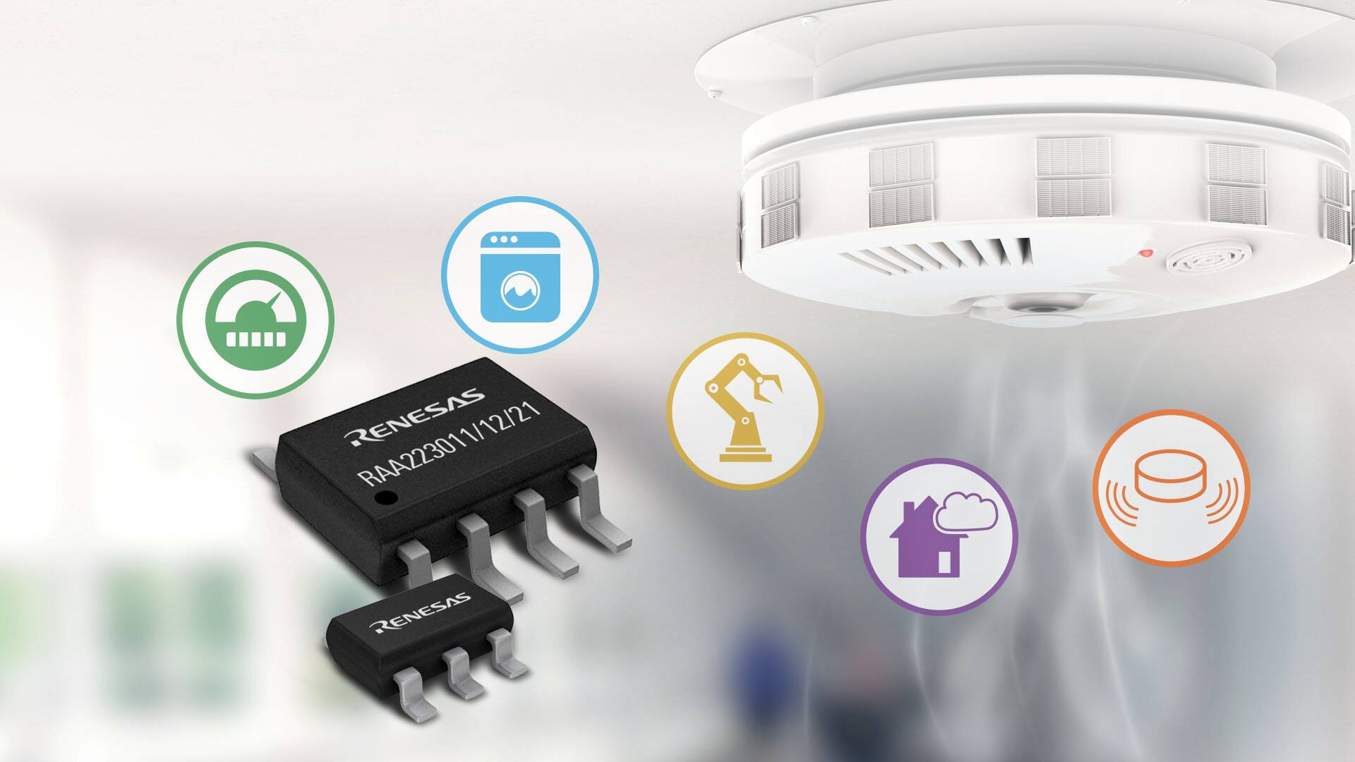
Renesas’ non-isolated AC/DC buck converter family are a series of universal input AC/DC switching buck regulators featuring a 700 V integrated MOSFET capable of delivering up to 8 W output power with an output voltage as low as 3.3 V and variable package options. It features a unique constant off-time control method that helps achieve ultra-low standby power, negligible EMI, and no audible noise. This product family also supports secondary-side feedback isolated flyback topology.
The RAA2230xx devices deliver superior power consumption, noise and EMI suppression, and reduced overall system cost. They are ideal for a wide range of applications, including home appliances, sensing systems such as smoke alarms and gas sensors, white goods, power meters, and industrial controls.
The motor control development tool RAJ306010 RSSK includes a development board and motor plus reference firmware and sample code.
Features
Support for both non-isolated buck and isolated flyback topologies, allowing customers to develop multiple types of AC input power supplies
Ultra-low standby power consumption: energy-efficient for customer designs
Unique constant off-time control mode: simple EMI design, no audible noise
Can provide 5 V or 3.3 V output directly; no need to include secondary LDO
Available in TSOT23-5, SOIC-8, and SOIC-7 package options: pin-to-pin compatibility for easy upgrade and replacement
STMicroelectronics’ ultra-compact piezoresistive absolute pressure sensor functions as a digital output barometer
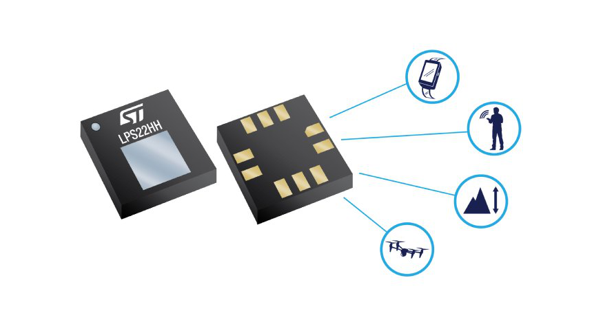
STMicroelectronics’ LPS22DF is an ultra-compact piezoresistive absolute pressure sensor that functions as a digital output barometer. The LPS22DF provides lower power consumption, achieving lower pressure noise than its predecessor. The device comprises a sensing element and an IC interface that communicates over I²C, MIPI I3CSM, or SPI interfaces from the sensing element to the application and supports a wide VDD IO range for the digital interfaces. The sensing element, which detects absolute pressure, consists of a suspended membrane manufactured using a dedicated process developed by ST.
The LPS22DF is available in a full-mold, holed LGA package (HLGA). It is guaranteed to operate over a temperature range extending from -40°C to +85°C. The package is holed to allow external pressure to reach the sensing element.
Features
260 hPa to 1260 hPa absolute pressure range
Current consumption down to 1.7 μA
Absolute pressure accuracy: 0.5 hPa
Low-pressure sensor noise: 0.34 Pa
High-performance TCO: 0.45 Pa/°C
Embedded temperature compensation
24-bit pressure data output
ODR from 1 Hz to 200 Hz
SPI, I²C, or MIPI I3C interfaces
Supports 1.08 V digital interface
Embedded FIFO
Interrupt functions: data ready, FIFO flags, pressure thresholds
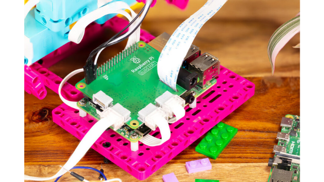
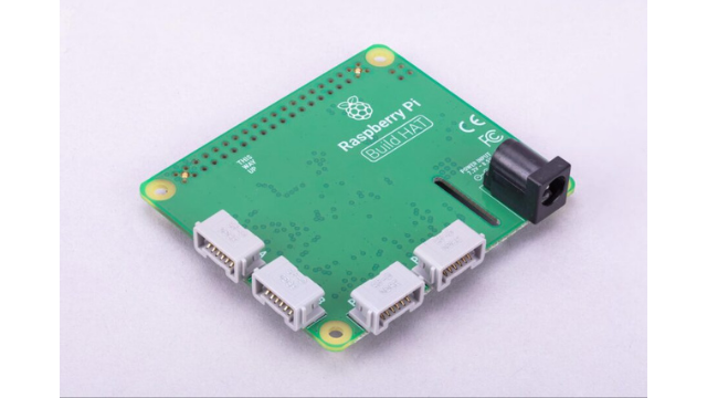
Raspberry Pi has always been at the forefront of all the major developments in the embedded device industry. From the most popular SBCs to power development boards and supporting HATs, the foundation has collaborated with LEGO Education to ease the integration of LEGO Technic motors and sensors with Raspberry Pi computers. To attract more developers and users from the education industry, Raspberry Pi Build HAT creates a unique and fun experience to build applications.
“We are excited to work with Raspberry Pi to provide tools for students, teachers, and makers all over the world to expand their creative digital skills and discover hands-on learning experiences,”
said Andrew Sliwinski, Head of Product Experience, LEGO Education.
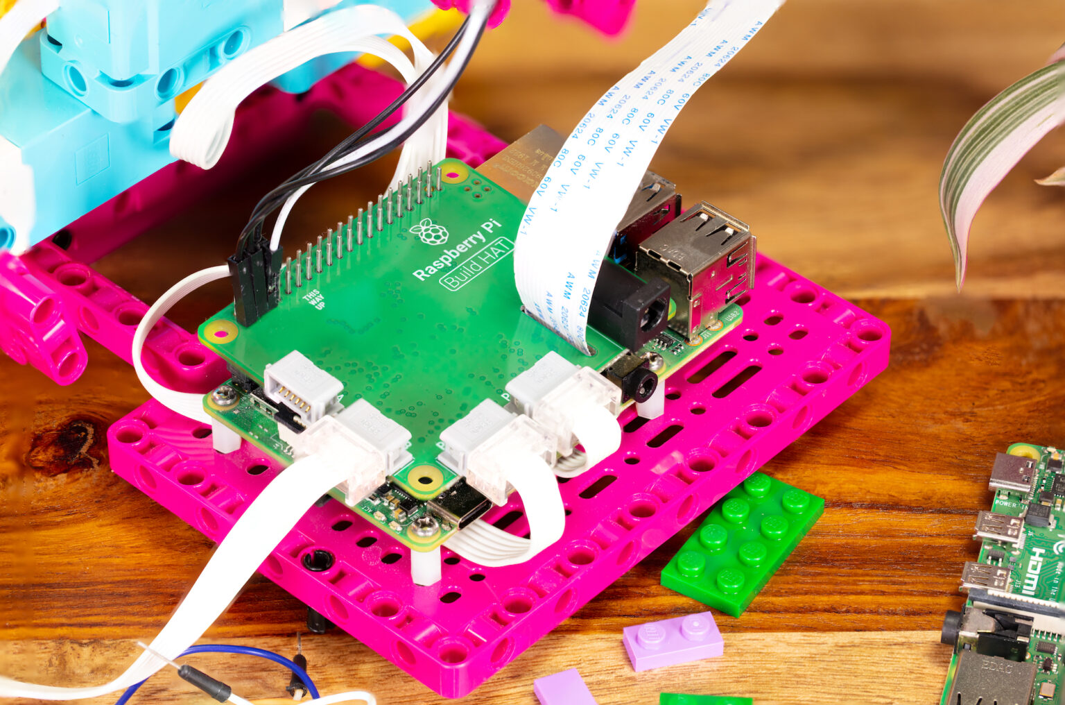
The $25 Raspberry Pi Build HAT lets you control up to four LEGO Technic motors and sensors from the LEGO Education SPIKE Portfolio. This is an add-on board that fits on any Raspberry Pi computer with 40-pin headers. The sensors that can be interfaced through the Raspberry Pi Build HAT include a distance sensor, a color sensor, and a force sensor. The angular motors are available in different sizes and include integrated encoders that can be queried to find their position.
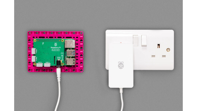
When it comes to powering the HAT, there is a separate power supply available for the hardware. This new power supply can power the Raspberry Pi Build HAT as well as the RPi computer. To make the build process easy for the users, the manufacturer has provided an all-new Python library. This might look familiar to those who have already worked on the Raspberry Pi libraries like gpiozero or the one for the Sense HAT.
For robotic applications, the HAT seems like the perfect fit for your Raspberry Pi computer. If you are new to the environment, Raspberry Pi has some projects listed on the website that uses Raspberry Pi Build HAT. Once you buy the hardware, the getting started guide will help initialize and interface the sensors.
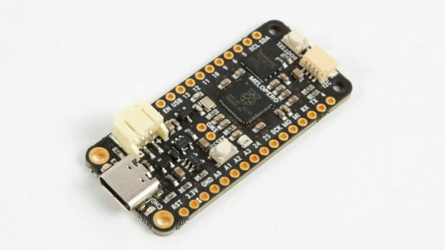
Italian embedded device manufacturer Melopero has recently launched a powerful new development board based on the Raspberry Pi’s in-house silicon tapeout RP2040. Lately, we have seen many manufacturers designing a feather form factor development board on RP2040, like the Adafruit Feather RP2040 and ItsyBitsy RP2040. With this development board, you can now build applications related to remote IoT applications like Smart Agriculture.
The Melopero’s Shake RP2040 development board comes with a battery charger based on the MCP73831 for the use of LiPo 1-cell. Since the fast charger is set to ~200 mA, the battery capacity has to be at least 500 mA. The board also features a battery monitor that sends an alert when the battery voltage drops below 3.4V. To increase the compatibility in building more applications, the design supports Qwiic/Stemma QT connector to connect Adafruit and SparkFun sensors.
Battery: Low battery monitor and LiPo battery charger
LEDs: User LED, Charge status LED, WS2812 RGB LED
Power: USB-C input power
Programmability: C/C++, MicroPython, CircuitPython with Arduino IDE
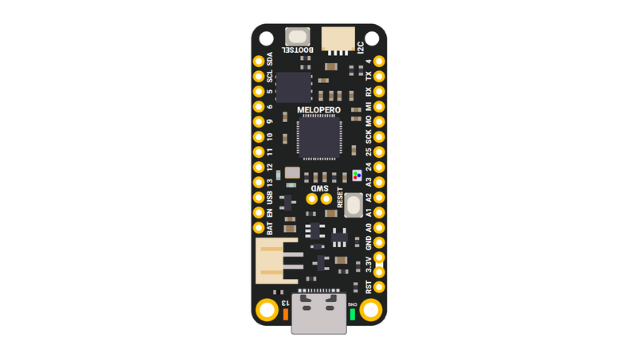
As mentioned earlier, the low battery monitor is connected to the GP17. If the pin detects a low battery alert, the battery monitor output will be HIGH when the voltage reaches 3.6V. However, it is important to note that this feature only works when the battery is not charging or the power input is not connected via USB-C. Through these features, remote IoT applications are one aspect of increasing efficiency. A detailed pinout diagram for your reference will be provided by the manufacturer as a getting started guide.
The Melopero’s Shake RP2040 gets the support for C/C++, MicroPython, and CircuitPython. This is common support for all the RP2040-based development boards. The higher cost of €22.90 (~$27) for the Shake RP2040 is justified by the additional connectors. The guide for programming the board will be provided on the product page.
Just a year after RAKwireless launched 14 new WisBlock modules for IoT prototyping, the company is back with a new WisBlock RAK11310 Core, alongside a Wisblock baseboard, 11 new modules, and one new IO Extension cable.
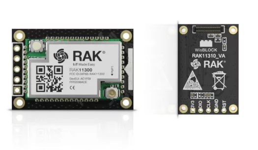
RAK11310 CORE MODULE
This new RAK11310 Core is one of the first in the market to combine a Raspberry Pi RP2040 with a LoRa transceiver from Semtech – a perfect core module for IoT applications requiring LoRa connectivity. Suitable for a number of applications like home automation, sensor networks, building automation, and personal area networks applications (health/fitness sensors, and monitors, etc.).
The core module can be programmed with Arduino IDE, PlatformIO, or MicroPython.
Features and Specifications:
RAK11300 WisDuo LPWAN Module:
Raspberry Pi RP2040 dual-core Cortex-M0+ microcontroller running at 133MHz; 246 kB RAM
Semtech SX1262 low power high range LoRa transceiver
The Wisblock RAK11310 core is available for $9.95 while the RAK11300 RP2040 LoRaWAN module sells for $6.95. Other details can be found on the documentation site here.
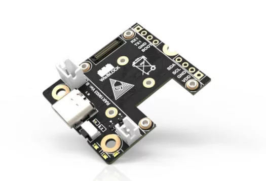
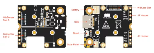
RAK19003 WISBLOCK BASE BOARD (the smallest WisBlock baseboard so far)
Features and Specifications:
Wisconnector for WisBlock Core MCU
2x 24-pin Wiconnectors for WisBlock modules
I2C, UART, GPIOs and analog input
USB Type-C debug port
1x Reset button
2 user-definable LED’s
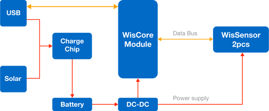
5V power supply via USB port/3.7V power supply via LiPo batteries/5V via solar panel(s)/Combination of multiple power inputs
Dimensions: 35 x 30mm
The baseboard is currently available for $8.99. Other details can also be found on the company’s website.
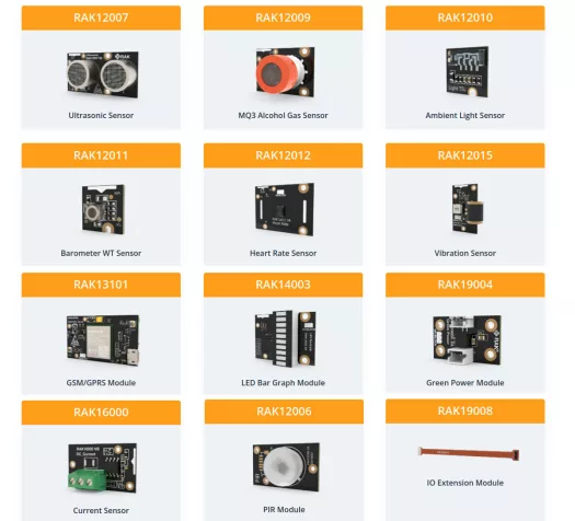
The company also released 11 other modules with a new 120mm RAK19008 IO extension cable for large WisBlock modules.
Here’s a list of the 11 new modules:
RAK12006 PIR Module: Motion detection sensor (can be used for light automation as well as for detecting intruders in security systems).
RAK12007 Ultrasonic Sensor – Obstacle detection and distance measurement module (uses ultrasonic waves to detect objects up to a distance of 400 cm with up to 3mm accuracy and 15° detection angle).
RAK12009 MQ3 Alcohol Gas Sensor – For detecting alcohol concentrations in the air between 25 to 500 ppm (can be used in low-cost breathalyzers or air quality sensing system).
RAK12010 Ambient Light Sensor – For measuring light intensity from 0 lux ~ 120000 lux.
RAK12011 Barometer WT Sensor – A water-resistant barometric air pressure and temperature sensor for outdoor and weather applications (for measuring pressure from 260 ~ 1260 hPa).
RAK12012 Heart Rate Sensor – Based on the MAX30102 low-power sensor (for measuring heart rate and pulse oximetry).
RAK12015 Vibration Sensor – For detecting unusual vibrations on motors and machinery.
RAK13101 GSM/GPRS Module – Cellular modern for sending data over GSM to the cloud
RAK14003 LED Bar Graph Module – For displaying status information (has 10x customizable LEDs)
RAK19004 Green Power Module – External power converter to recharge WisBlock with renewable power sources like wind generators, water turbines and solar panels.
RAK16000 Current Sensor – DC Current Sensor module that can measure current from 0 to 3A.
Details on the modules plus how to go about buying any can be found on their product page.
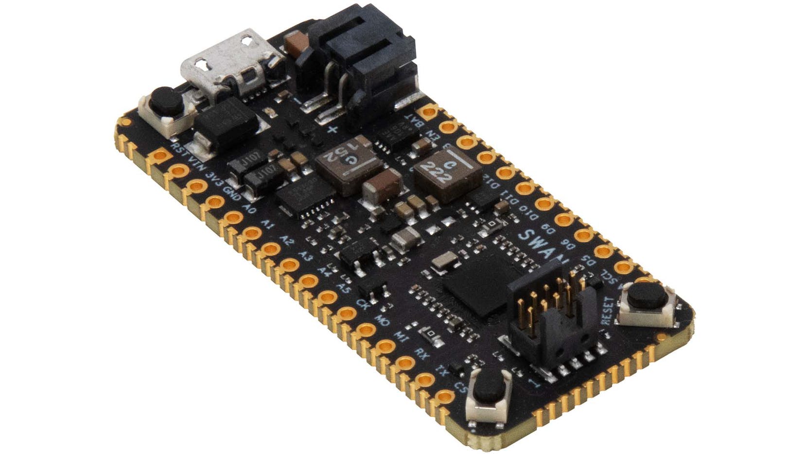
A handful of microcontrollers for IoT applications have hit the hardware ecosystem over the past years, allowing for easy development of embedded and standalone IoT-based systems. Most of these MCUs and processor chips, however, are expensive, power-consuming, and lack large memory and I/O expandability. The latest release from Blue Wireless seems to be an all-in-one solution that puts all these into consideration.
Blue Wireless SWAN is an embeddable microcontroller based on the STM32L4R5 chip architecture. It is an ultra-low-power, 120 MHz Arm Cortex-M4 Core board with a large memory of 2 MB of flash and 640 KB of RAM and castellated-edge 55 GPIO ports allowing for applications demanding large memory and I/O expansion with affordable cost. SWAN is targeted at accelerating the development of battery-powered IoT systems from DIYs systems and Makers prototyping to high volume implementation. The board is perfect for applications such as edge inferencing and remote sensing and monitoring at an economical cost.
The board is powered via either a USB, a battery, or a regulated supply. It offers a 2A regulator, switchable with software to regulate external sensor supply. The board draws a total of 8 uA in its low-power mode while offering its full memory capacity in operation. That makes it a good fit for battery-powered systems and a big plus why it should be developers’ favorite.
SWAN is also suitable with feather-compatible boards, allowing for prototyping and field implementation. The board offers flexibility to developers with compatibility with Adafruit’s myriad sensors and FeatherWing-compatible carriers. That means that these boards can go along with Swan at the same time. Swan can be soldered directly to a parent PCB integrating desired sensors, providing efficient use of its I/O expandables.
Key Features and Specifications:
Ultra-low-power Arm Cortex-M4 core clocked at 120Mhz
STM32L4R5-based microcontroller
2MB of flash
640KB of RAM
Castellated-edge access to 55 GPIO ports including 8x analog, 16x digital, 4x I2C, 3x SPI
USB OTG full speed
1x 14-channel DMA
tRNG
12-bit ADC
2x 12-bit DAC
Low-power RTC, and CRC calculation peripherals
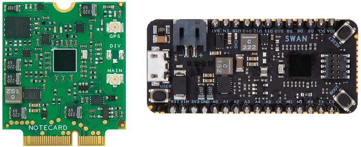
SWAN is compatible with C/C++, Arduino, CircuitPython, and a CORTEX Debug connector allowing for development and deployment with Visual Studio Code, IAR, and STM32cubeIDE, when provided with an STLNK-V3MINI add-on. Its Feather devKit includes a Notecard and a Notecarrier.
SWAN is available as a standalone board in a $99Feather Starter Kit or as an embeddable board paired with its Notecard. You can however get SWAN without the Notecarrier for $25.
Other useful resources and information on SWAN and STM32L4R5ZI can be found on the Blueswireless website.
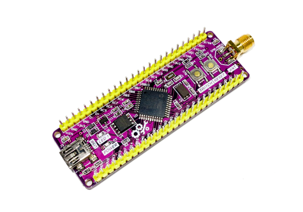
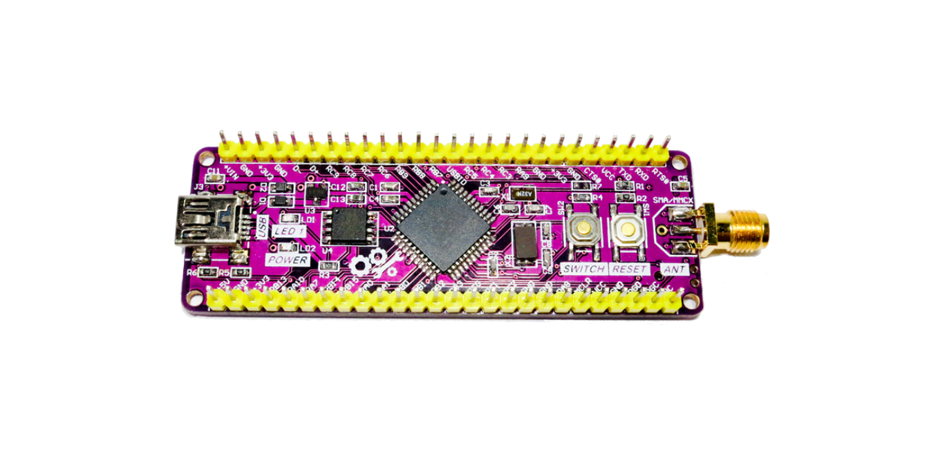
Medtronic’s tinyWireless PIC32 development board is a low-cost, low-power Microchip PIC32-based, Arduino compatible wireless development board. Despite its compact form factor, it can also be mounted in a solderless breadboard or utilized as an independent development board.
Deeper Look at tinyWireless PIC32 Development board
The tinyWireless PIC32 model is built around a powerful PIC32MX250F128D core 32-bit MIPS32 M4K microcontroller. It can operate at a frequency of up to 50MHz, offering a total of 83 Million Instructions Per Second (MIPS). The hardware also features 32kB of RAM and 128kB of flash program memory. There are 35 user-configurable IO pins on the board, as well as two UARTs, two SPI buses, two I2C buses, and five 16-bit timers. In addition, the PIC32’s RTCC hardware and the installed 32.768kHz watch crystal provide full support for Real-Time Clock (RTCC) functionality.
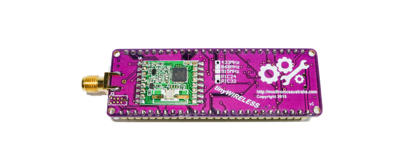
This flexible development platform supports the long-range ISM band RFM69HW wireless transceiver. It has wireless transmission speeds of up to 300kbps with AES-128 bit encryption to prevent wireless sniffing. Depending on the data rate and RF environment, these modules can communicate over many kilometers. What makes it even more remarkable is that the RFM69HW is programmable in both narrow-band and wide-band communication modes without the requirement for external components to be modified.
The RFM69HW module is also a perfect alternative for battery-powered applications due to its wide operating voltage range of 1.8–3.6 V and low current consumption. Plus, the module gives a +20dBm output power and can be purchased in 433MHz, 868MHz, or 915MHz frequency variations. Furthermore, tinyWireless has a 32Mbit SPI FLASH and USB or UART ports for communication with your PC, making it ideal for data logging applications.
Talking about the software support, the board can be programmed natively in C/C++ for ultimate power and control. It can be compiled using Microchips Free XC32 C/C++ compiler. Plus, tinyWireless also works with Microchip’s Harmony Integrated Software Framework, which allows the PIC32 hardware to be abstracted from the programmer, hence speeding up software development.
“In addition, tinyWireless development boards are able to run your favorite Arduino sketches, using a number of open-source tools such as chipKit MPIDE or Pinguino. TinyWireless has a Fubarino Mini compatible footprint to simplify Arduino use with the chipKit MPIDE,”
says Medtronics.
The tinyWireless PIC32 development board is available on Tindie at $30. For more information visit the product page. Images and technical specifications have also been taken from the product page.
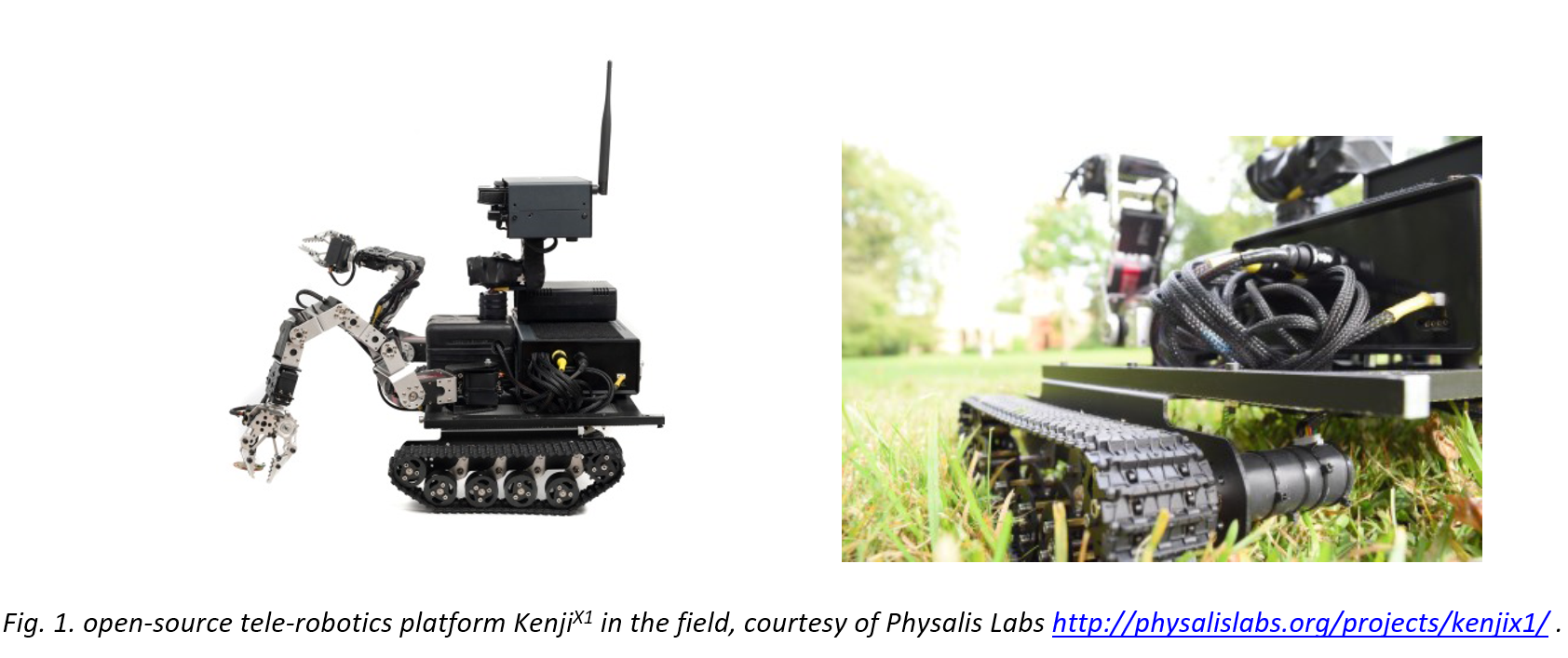
Tele-Robotics platform KenjiX1 enables new horizons of Human-Machine Interaction, and interfacing with the real world, both in reality or virtually. It is a highly adaptable system, to give unlimited freedom and flexibility to build upon. A „Truly Modular“ tele-robotics rover, which is built for automation, active monitoring, and terrain exploration.
Physalis Labs “roboDrive Engine” which KenjiX1 relies upon, is a very flexible tool to jumpstart into telerobotics development for students, developers, and makers.
In Fig.1. Illustration of the KenjiX1 Rover equipped with payload containers, front-side mounted manipulators, and grippers to handle objects.
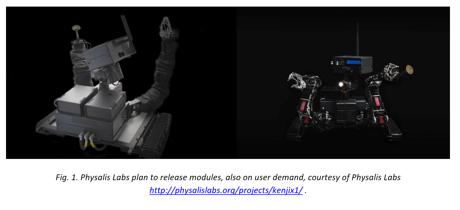
Thanks to its unconstrained design and modular structure, KenjiX1 can be re-configured in minutes according to the application’s demand. It brings a flexible hardware base, high degree of customization and built-in sensing systems, which, in-fact, can be utilized for real-life measurements – on the field or in lab.
With an uptime of more than 8 hours, the operator has an access to high-power mechanized arms, onboard LIDARs, distance sensors, environmental sensors, temperature and vibration measuring modules, analog sensors array which enables users to start deploying and generating real-world data right away, eliminating the need to purchase expensive and complicated external instrumentation.
Scalable and Adaptable…
SLAM, conductive sensing, and logging of vibrations, streaming environmental data over the network, storing and evaluating onboard, as well as streaming, is possible. It has been designed around the most popular and affordable hardware on the market.
Work Remotely via Tele-Presence…
Your Remote companion in Home-Office?
No matter which field are you coming from, now you can run that dangerous chemical tests inside the reaction chamber directly from your home office. KenjiX1 will handle the rest of and hazardous tasks for you.
Small, robust and powerful board with Wi-Fi and Bluetooth connectivity combined with its low power architecture makes it a practical solution.
This month oemsecrets.com has teamed up with Farnell to giveaway an Arduino MKR WiFi 1010 Development Board to two lucky winners. Simply follow the link below to enter.
Get extra entries into the giveaway by following us and sharing this article on Instagram, LinkedIn, Facebook or Twitter using #oemsecrets or @oemsecrets.
Arduino MKR WiFi 1010 Development Board
The Arduino MKR WiFi 1010 is the easiest point of entry to basic IoT and pico-network application design. Whether you are looking at building a sensor network connected to your office or home router, or if you want to create a BLE device sending data to a cellphone, the MKR WiFi 1010 is your one-stop-solution for many of the basic IoT application scenarios.
We’re pleased to announce the 2 winners of the @arduino MKR WiFi 1010 in partnership with @Farnell_Avnet are “Gus M.” & “Dan T.”. We’ll be in touch with you via email to get your shipping details. Congrats to both of you & thanks to everyone who entered #winners 🎉 #oemsecretspic.twitter.com/21uKaoArMA
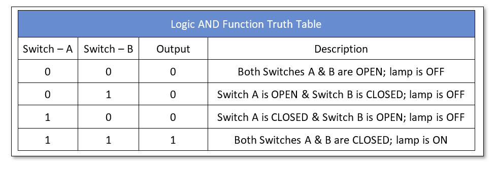
The output of Logic AND Function is true only when all of its inputs are in true logic states otherwise the output of Logic AND Function will be false (in case any of the inputs is false).
All of the logic functions follow Boolean Algebra and relevant theorems. The Boolean Algebra is similar to that of Normal Algebra in that it follows similar laws and theorems except the Boolean Algebra involves a set of values either “TRUE” or “FALSE” but not both at the same time. In normal algebra, 1 + 1 = 2 but in Boolean algebra 1 + 1 = 1 as there are only two values [True (1) and False (0)] in the short set, and one of them only occurs at a time, not both. In other words, in Boolean Algebra A + A = A, not 2A as compared to normal algebra.
The Boolean Algebra was developed by George Boole in 1854 and authored “The Laws of Thought” which contains Boolean Algebra based on a simplified version of the Group or Set.
The logic functions or gates are based on Boolean Algebra and describe logic functions in simple switching actions performed by logic gates. The basic logic gates include AND, OR, and NOT logic gate functions.
The logic AND function require two or more inputs and expects a similar state (TRUE) of inputs at the same time in order to output a TRUE logic. At any instant, any of the inputs in a FALSE state leads the AND logic to output a FALSE state. In the following figure, a symbol along with the algebraic function of logic AND gate is shown.
Figure 1: The AND Symbol
In terms of Electrical Circuit, the logic AND functions are represented by switches connected in “Series”. In Boolean Algebra, the logic AND function is the product of inputs (variables) and is denoted by a dot (.) between the inputs which may not be necessary i.e. A.B or AB both represents a AND logic on inputs A & B. The occurrence of a state of operation of a switch is independent of the order in which they take place. It means that the logic AND function follows the Commutative Law i.e. A & B = B & A. According to Commutative Law, the output is independent of the position of a variable or input.
Presentation of AND Function using Switches
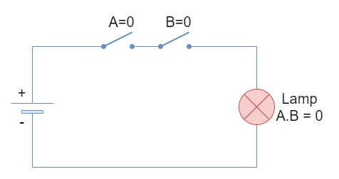
In the following figure, an electrical circuit comprising of two switches (A & B), a battery, and a lamp is shown. The electrical circuit is equivalent to a logic AND function where switches A & B represents logic AND functions inputs.
Figure 2: Both switches in open condition
The logical states of “0” & “1” represent a switch with “Open” & “Closed” positions, respectively.
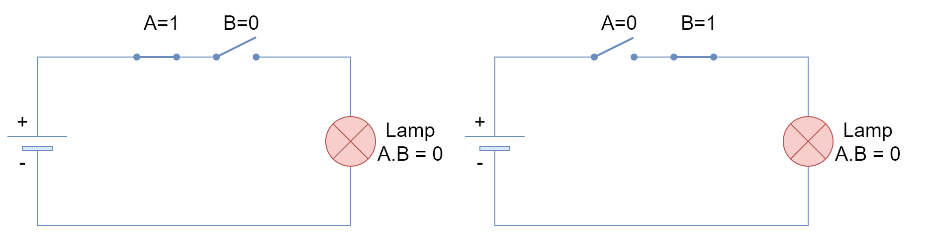
When both inputs are FALSE or “0” then both switches are open and the lamp remains at FALSE state as well. Likewise, when any of both inputs, irrespective of order or placement, is FALSE then the lamp still remains at FALSE state as shown in the following figure.
Figure 3: One switch in the closed position
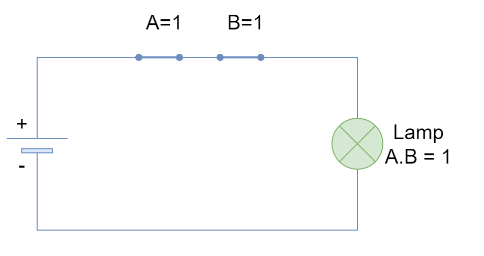
However, when both of the inputs are TRUE or “1” then the lamp turns to TRUE or ON state. The series combination of switches truly depicts the logic AND function where both switches (inputs) require to be TRUE to give a TRUE output.
Figure 4: Both switches in the closed position
Logic AND Truth Table
The above case of series switches is represented in the following truth table.
Boolean Algebra Laws
A brief overview of Boolean Algebra Laws relevant to logic AND is given below in form of figures. A more detailed overview of these laws is provided in another article on Boolean Algebra.
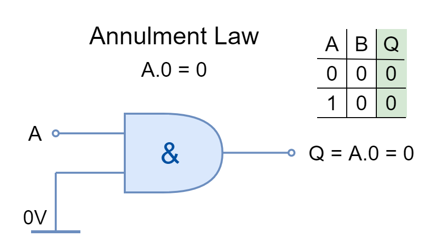
Annulment Law
The input AND’ed by ‘0’ or OR’ed by ‘1’ is stated as Annulment Law. It nullifies or diminishes the effect of the other input
Figure 5: The Annulment Law
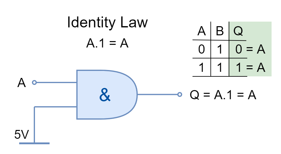
Identity Law
The input AND’ed by ‘1’ or OR’ed by ‘0’ is stated by Identity Law. It keeps the identity of the input.
Figure 6: The Identity Law
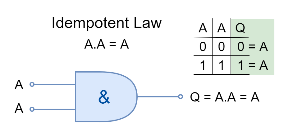
Idempotent Law
The same inputs AND’ed or OR’ed together are stated under Idempotent Law. The logical operation can be applied multiple times without changing the result.
Figure 7: The Idempotent Law
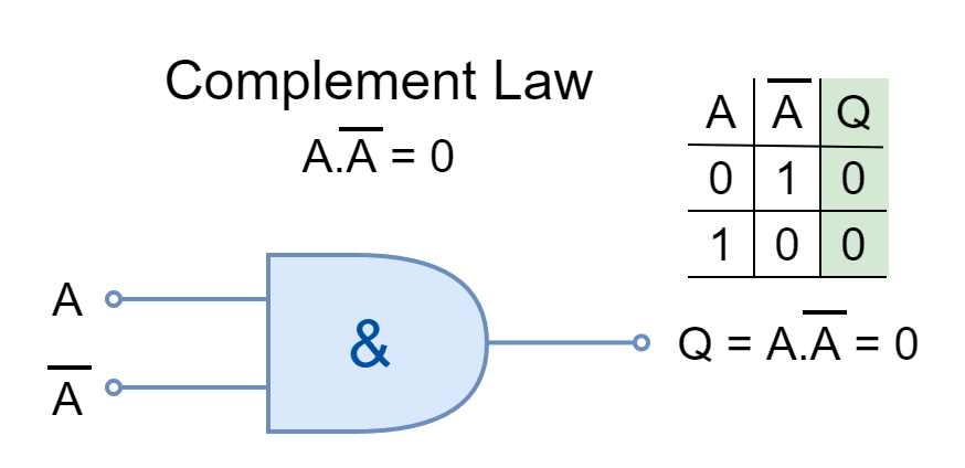
Complement Law
In Boolean Algebra, the complement is the opposite of a logical input such as ‘0’ is the complement of ‘1’ and vice versa. The input and its complement AND’ed or OR’ed together is described by Complement Law.
Figure 8: The Complement Law
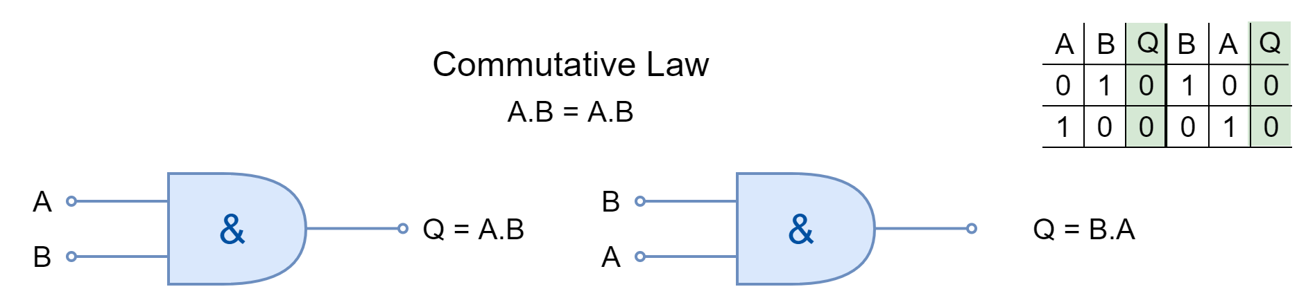
Commutative Law
The commutative law states that changing the order of operands (variables or inputs) does not change the result. In Boolean Algebra, the inputs can be interchanged without changing the results under commutative law.
Figure 8: The Commutative Law
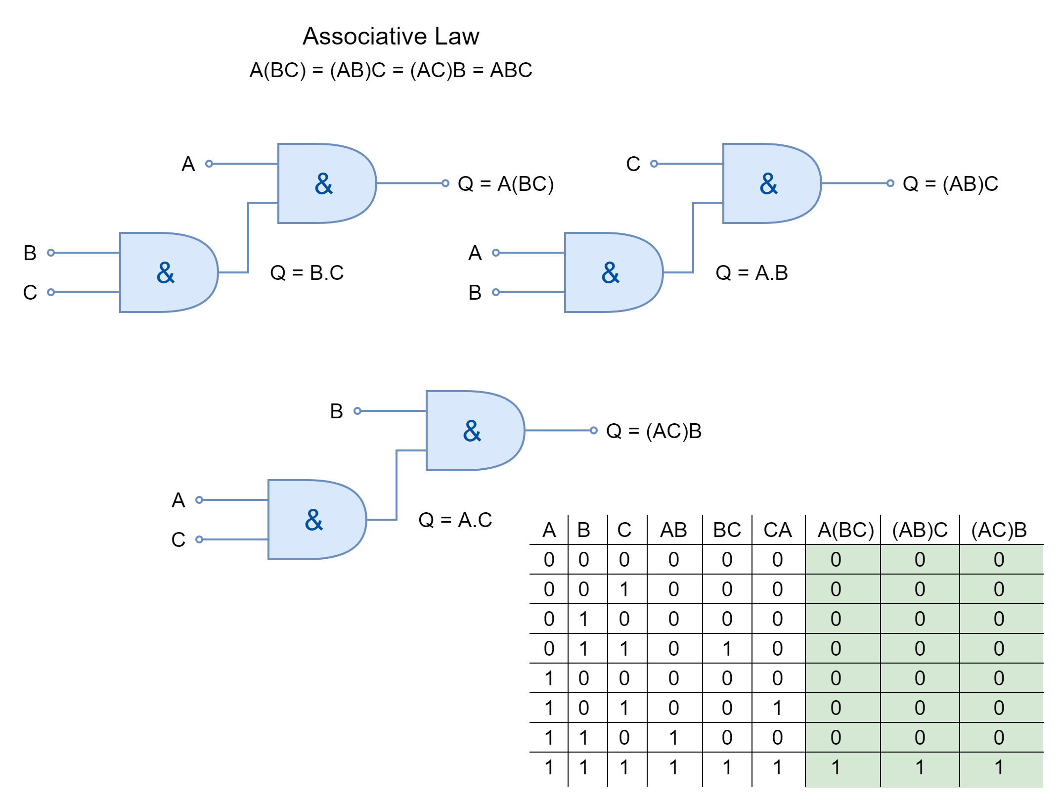
Associative Law
The associative law of multiplication states that the operands grouped differently in multiplication produce the same result. The inputs AND’ed together can be placed interchangeably to form different groups under the Associative Law.
Figure 10: The Associative Law
Commercially Available Logic AND Gates
The logic AND gates are available in form of I.C. packages which contain multiple AND gates with multiple inputs to each gate. The selection depends merely on the application and the number of logic are required. They come in both Transistor-Transistor Logic (TTL) and Complementary Metal Oxide Semiconductor (CMOS) family packages. A few commercially available logic AND gates are given below:
TTL 74LS08 2-input Quadruple AND Gates
TTL 74LS11 3-input Triple AND Gates
TTL 74LS21 4-input Double AND Gates
CMOS 4081 2-input Quadruple AND Gates
Conclusion
The logic AND function give output TRUE only when all of its inputs are in a TRUE state.
Any of the inputs in the FALSE state will lead the AND function to the FALSE output.
The logic AND function can be represented by an electrical circuit having two switches in series. When both of the switches are closed (inputs at TRUE states) then supply passes to the load/ lamp.
The logic AND gates can be cascaded together to obtain logic AND having more than two inputs.
The commercially available packages come in different I.C. packages. Each IC package contains multiple AND gates.