This is a back EMF signal conditioning circuit that can be used to develop high-voltage sensorless motor drivers. When a sensorless algorithm is used to control the BLDC motor speed, the Back EMF (BEMF) signals are used. Based on zero crossing of BEMF signals, motor commutation is decided in the firmware. The signal conditioning circuit has mainly three blocks: the first is a low-pass filter for each phase voltage the second is a comparator circuit for determining the zero crosspoints and the third is a high-speed optocoupler. The optocoupler provides isolation between high-voltage motor driver circuitry and microcontroller.
Inputs
- 3 Phase Signal inputs, from 3 Phase Motor connections
- Current Feedback across the shunt resistor of IPM/IGBT Emitter
- DC Bus Monitor, Over Voltage protection, 200V DC or 400V DC
Outputs
- 3 Phase Digital Zero Cross Signals (Optically Isolated)
- DC Bus Over Voltage, Normally High Output (Optically Isolated)
- Current to Voltage Cycle by Cycle Output (Optically Isolated)
- Optional Trip Optocoupler (Not Install, can be used, If current feedback circuit is not required)
Features
- Supply 5V DC for Analog Side (Inputs)
- Supply 5V DC For Digital Side (Outputs)
- Detect the Back EMF of 3 Phase Motor and Provides 3 TTL Outputs
- DC Bus Voltage Feedback Low or High TTL Output
- Optional Current Sense Circuit provides Cycle by Cycle voltage output proportional to motor current
- All outputs are optically Isolated, Frequency up to 20Khz
- Jumper J1 – Overvoltage protection, 200V or 400V DC (Close the Jumper for 400V)
- The project requires 2 separate 5V DC power supplies, Analog-Input side, and digital-Output side
- PCB dimensions: 47.94 x 42.70 mm
BLDC Motor Winding and Back EMF
To run a BLDC motor without sensors, it is important to sense the rotor magnet position with reference to the windings on the stator. In order to do this properly, the Back EMF on the unexcited winding is monitored. As the motor is spun, the voltage waveform on the three winding phases will be seen. There are 6 sectors, each 60 degrees wide, which accumulate to give one 360-degree electrical revolution of the motor. In each sector, two windings are excited: one with a high voltage and the other with a low voltage. The third winding is not excited. As the rotor rotates from one sector to another, a new set of windings is excited. The sequence of excitation in each sector is provided by the motor manufacturer. The winding in each sector that is not excited will be influenced by the Back EMF voltage. This voltage is not high or low, but a falling or rising voltage level, going symmetrically from a high-to-low or a low-to-high. It crosses the center, or star point voltage, at about 30 degrees before the next commutation point of the rotor. This center, or star point voltage, is also referred to as the zero-crossing voltage. Its value is exactly half the voltage applied to the excited windings of the motor. These signals can be interfaced to fast ADV to sense the zero-crossing point. Having sensed the zero-cross point, it can predict the time required for the next commutation phase.
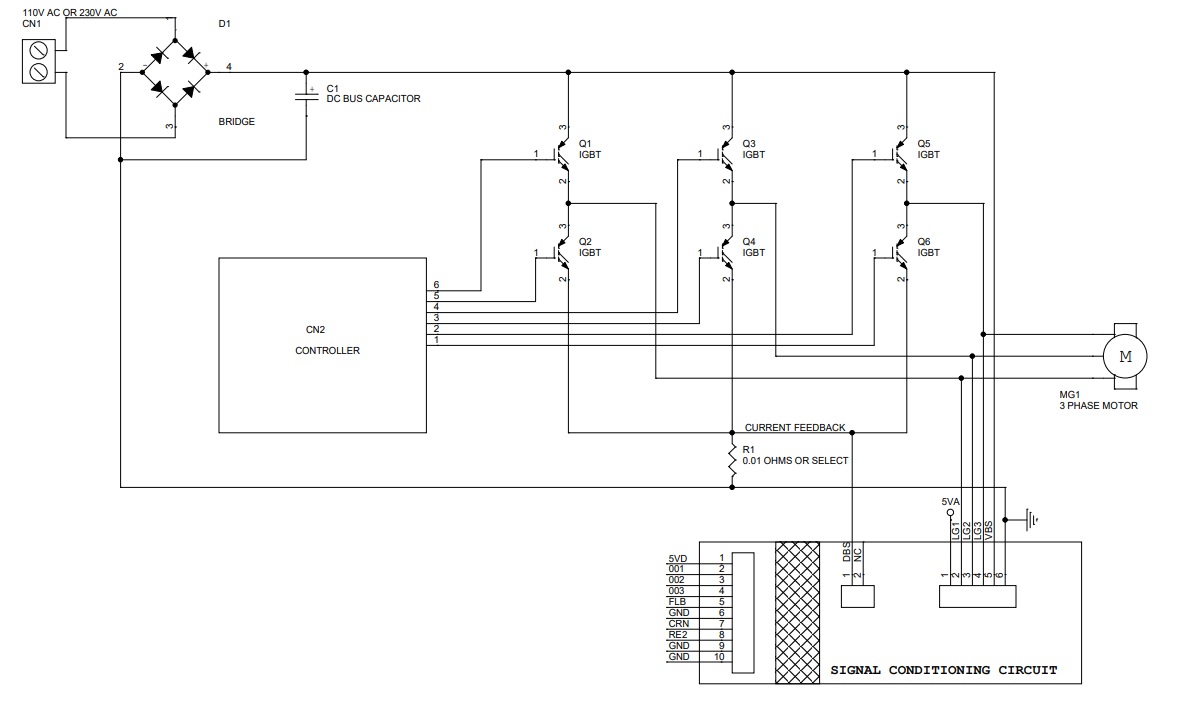
The board takes signals from 3 motor connections and provides isolated 5V TTL signal which can be further interfaced to a microcontroller or DSP. Board can take direct inputs from high-voltage 180V or 330V DC, AC IPM modules, or 3 phase MOSFET/IGBT-based inverters. This board can be modified to be used with lower voltage motor drivers, calculate the input divider resistors value as per motor voltage.
Current Feedback (IC U4, U5, U6) – Optional Do Not Populate
Optional current to voltage circuit can help to measure the current of IPM module or 6 IGBT/MOSFET inverter, the block measures the current across the shunt resistors and provides a proportional voltage output, this output is optically isolated. This block is created using U4, U5, U6 chips, Gain can be set using R54. The circuit provides near-zero output when a current is not flowing, otherwise, the output is 3V/Amp.
Bus Voltage Feedback/Over Voltage Fault (Op-Amp U1D)
The DC bus voltage is attenuated using a voltage divider and compared with a fixed reference signal using an external comparator. On the board, when jumper J1 is open, the overvoltage is set to 200V on the DC bus. If jumper J1 is shorted, then the overvoltage limit is 400V. The Fault FL pin is used to monitor the overvoltage condition. Normally FL pin is low, goes high when overvoltage condition occurs.
Credits: Reference Microchip Application Notes
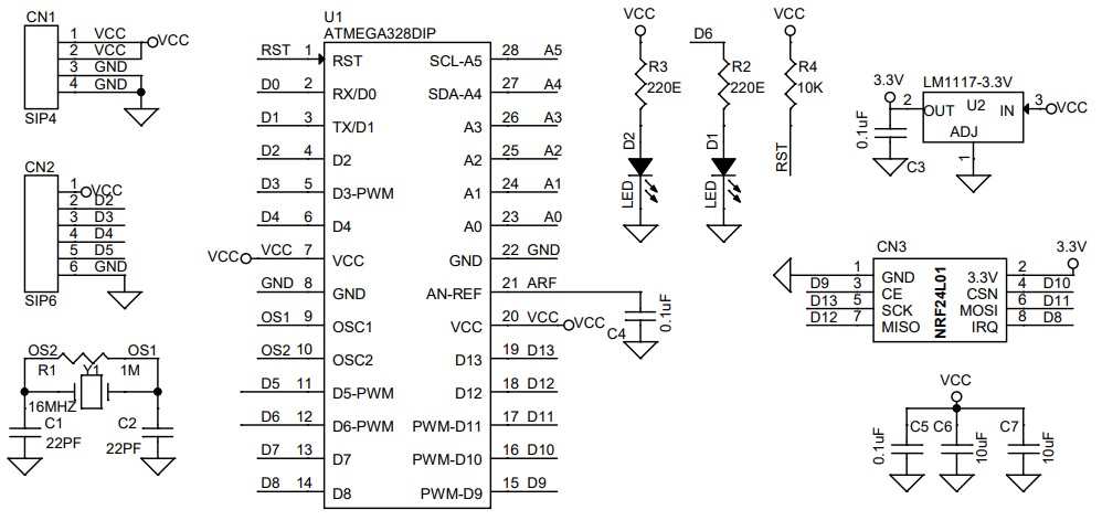
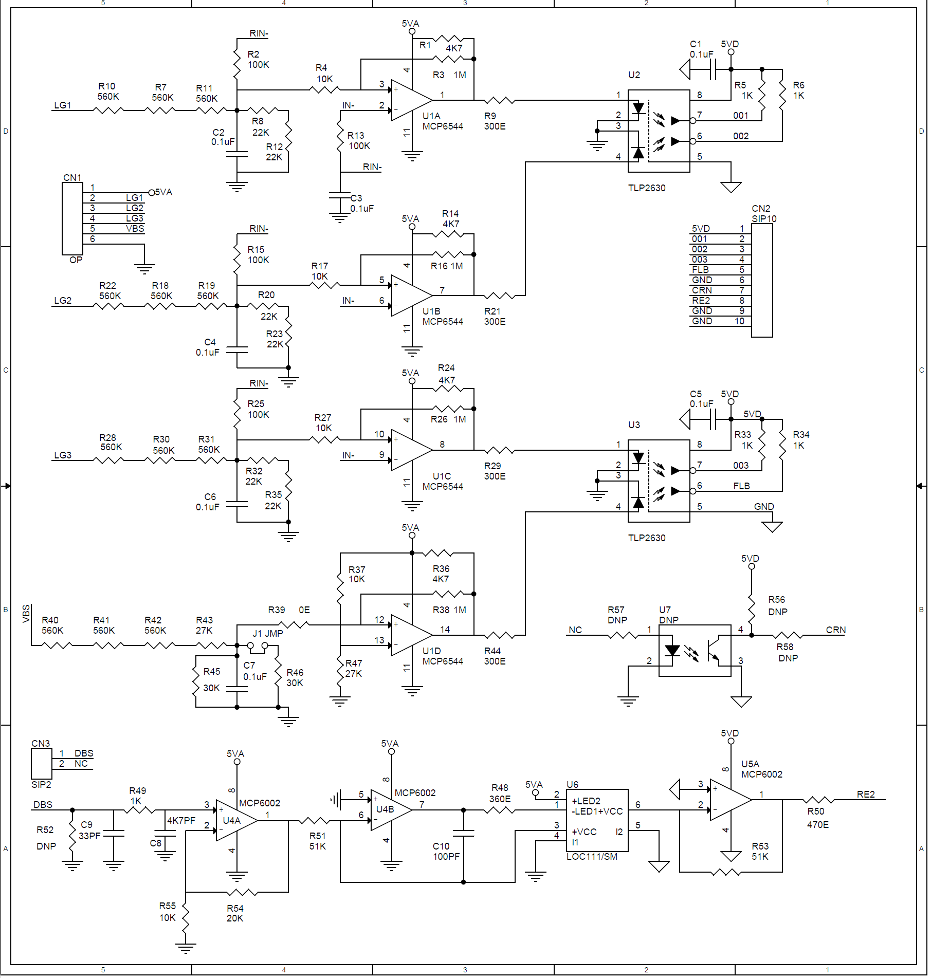
Schematic
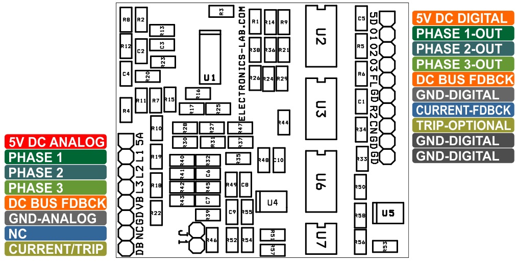
Parts List
| NO | QNTY. | REF | DESC. | MANUFACTURER | SUPPLIER | PART NO |
|---|---|---|---|---|---|---|
| 1 | 1 | CN1 | 6 PIN MALE HEADER PITCH 2.54MM | WURTH | DIGIKEY | 732-5319-ND |
| 2 | 1 | CN2 | 10 PIN MALE HEADER PITCH 2.54MM | WURTH | DIGIKEY | 732-2670-ND |
| 3 | 1 | CN3 | 2 PIN MALE HEADER PITCH 2.54MM | WURTH | DIGIKEY | 732-5315-ND |
| 4 | 7 | C1 to C7 | 0.1uF/50V SMD SIZE 0805 | MURATA/YAGEO | DIGIKEY | |
| 5 | 1 | C8 | 4K7PF/50V SMD SIZE 0805 | MURATA/YAGEO | DIGIKEY | |
| 6 | 1 | C9 | 33PF/50V SMD SIZE 0805 | MURATA/YAGEO | DIGIKEY | |
| 7 | 1 | C10 | 100PF/50V SMD SIZE 0805 | MURATA/YAGEO | DIGIKEY | |
| 8 | 1 | J1 | 2 PIN MALE HEADER PITCH 2.54MM | WURTH | DIGIKEY | 732-5315-ND |
| 9 | 4 | R1,R14,R24,R36 | 4K7 5% SMD SIZE 0805 | MURATA/YAGEO | DIGIKEY | |
| 10 | 4 | R2,R13,R15,R25 | 100K 5% SMD SIZE 0805 | MURATA/YAGEO | DIGIKEY | |
| 11 | 4 | R3,R16,R26,R38 | 1M 5% SMD SIZE 0805 | MURATA/YAGEO | DIGIKEY | |
| 12 | 5 | R4,R17,R27,R37,R55 | 10K 5% SMD SIZE 0805 | MURATA/YAGEO | DIGIKEY | |
| 13 | 5 | R5,R6,R33,R34,R49 | 1K 5% SMD SIZE 0805 | MURATA/YAGEO | DIGIKEY | |
| 14 | 12 | R7,R10,R11,R18,R19,R22 | 560K 1% SMD SIZE 0805 | MURATA/YAGEO | DIGIKEY | |
| R28,R30,R31,R40,R41,R42 | 560K 1% SMD SIZE 0805 | MURATA/YAGEO | DIGIKEY | |||
| 15 | 6 | R8,R12,R20,R23,R32,R35 | 22K 1% SMD SIZE 0805 | MURATA/YAGEO | DIGIKEY | |
| 16 | 4 | R9,R21,R29,R44 | 300E 1% SMD SIZE 0805 | MURATA/YAGEO | DIGIKEY | |
| 17 | 1 | R39 | 0E SMD SIZE 0805 | MURATA/YAGEO | DIGIKEY | |
| 18 | 2 | R43,R47 | 27K 1% SMD SIZE 0805 | MURATA/YAGEO | DIGIKEY | |
| 19 | 2 | R45,R46 | 30K 1% SMD SIZE 0805 | MURATA/YAGEO | DIGIKEY | |
| 20 | 1 | R48 | 360E 1% SMD SIZE 0805 | MURATA/YAGEO | DIGIKEY | |
| 21 | 1 | R50 | 470E 1% SMD SIZE 0805 | MURATA/YAGEO | DIGIKEY | |
| 22 | 2 | R51,R53 | 51K 1% SMD SIZE 0805 | MURATA/YAGEO | DIGIKEY | |
| 23 | 5 | U7,R52,R56,R57,R58 | DNP | OPTIONAL | ||
| 24 | 1 | R54 | 20K 1% SMD SIZE 0805 | MURATA/YAGEO | DIGIKEY | |
| 25 | 1 | U1 | MCP6544 | MICROCHIP | MOUSER | 579-MCP6544-E/SL |
| 26 | 2 | U2,U3 | TLP2630/VO2630 | VISHAY | MOUSER | 782-VO2630 |
| 27 | 2 | U4,U5 | MCP6002 OR LM358 | MICROCHIP | DIGIKEY | MCP6002-E/SN-ND |
| 28 | 1 | U6 | LOC111/SM | IXYS | DIGIKEY | CLA116-ND |
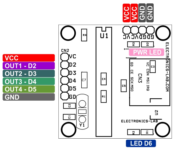
Connections
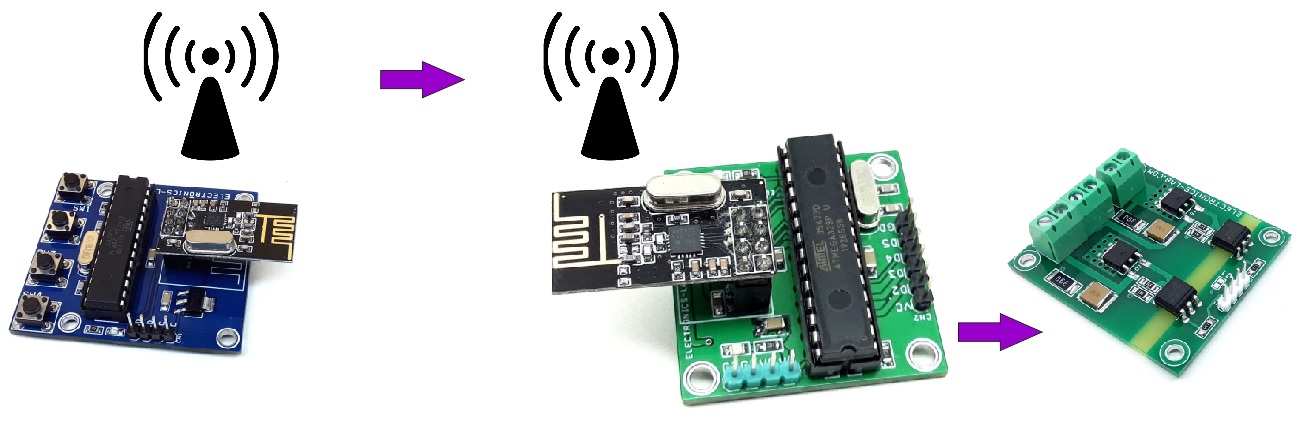
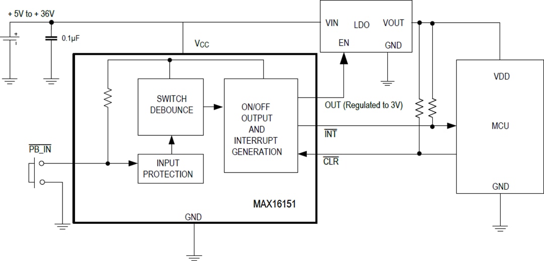
Block Diagram
Gerber View
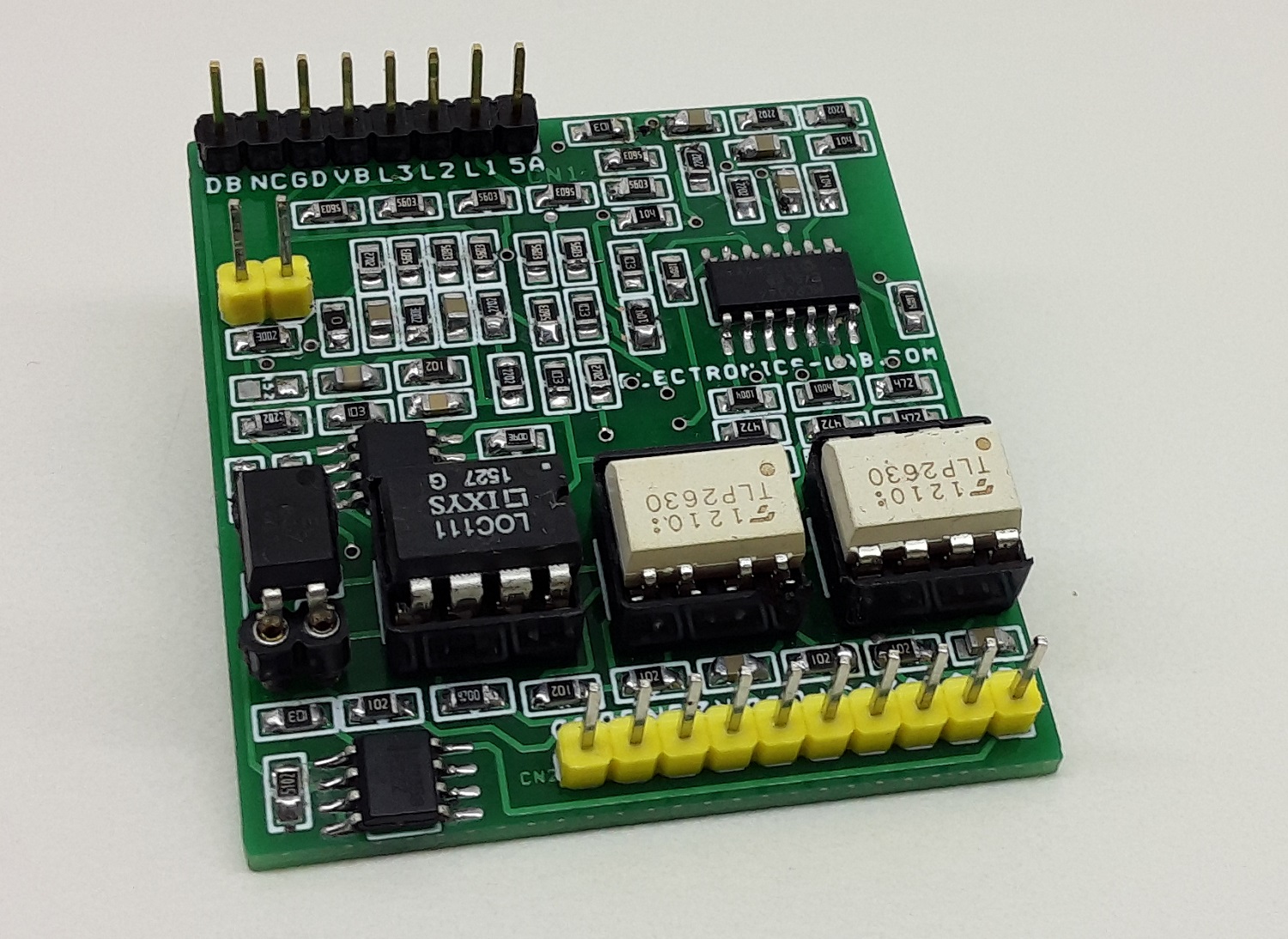
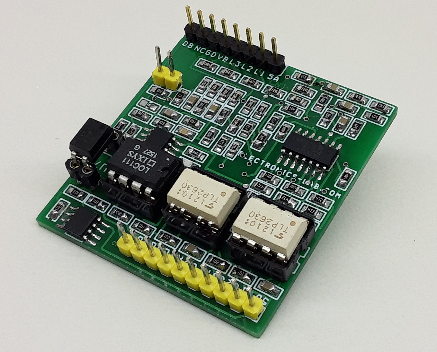
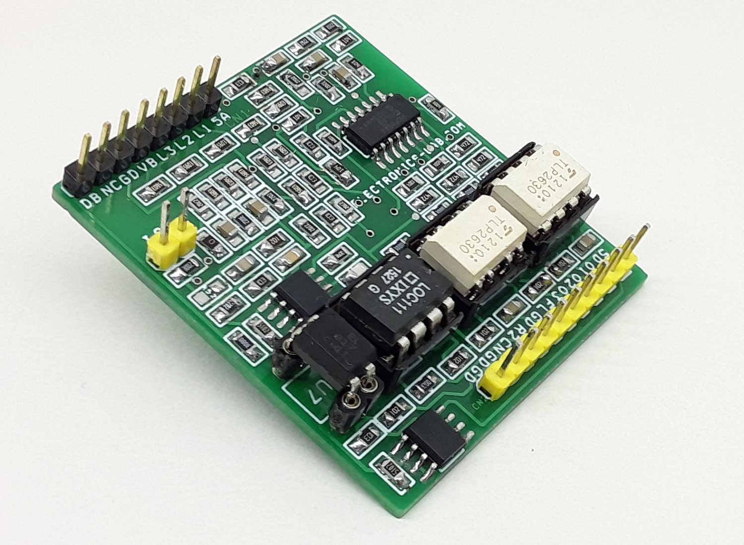
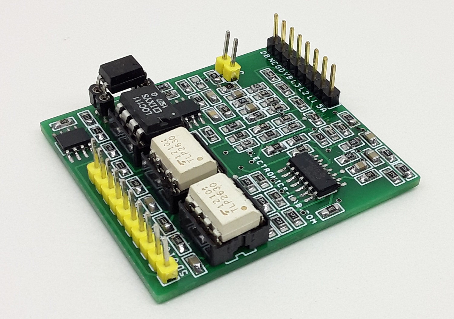
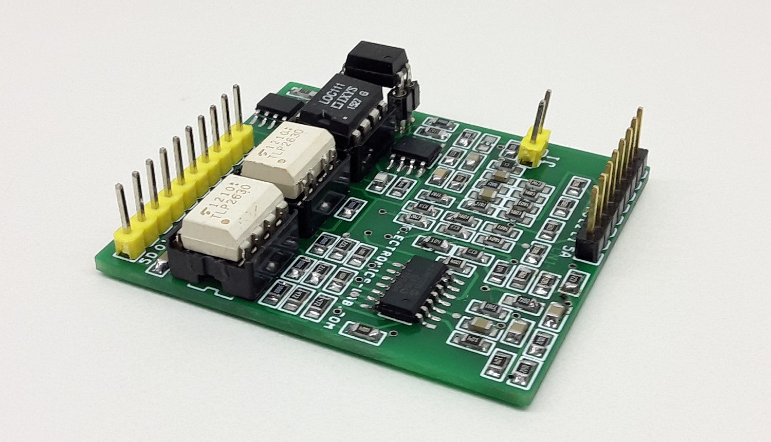
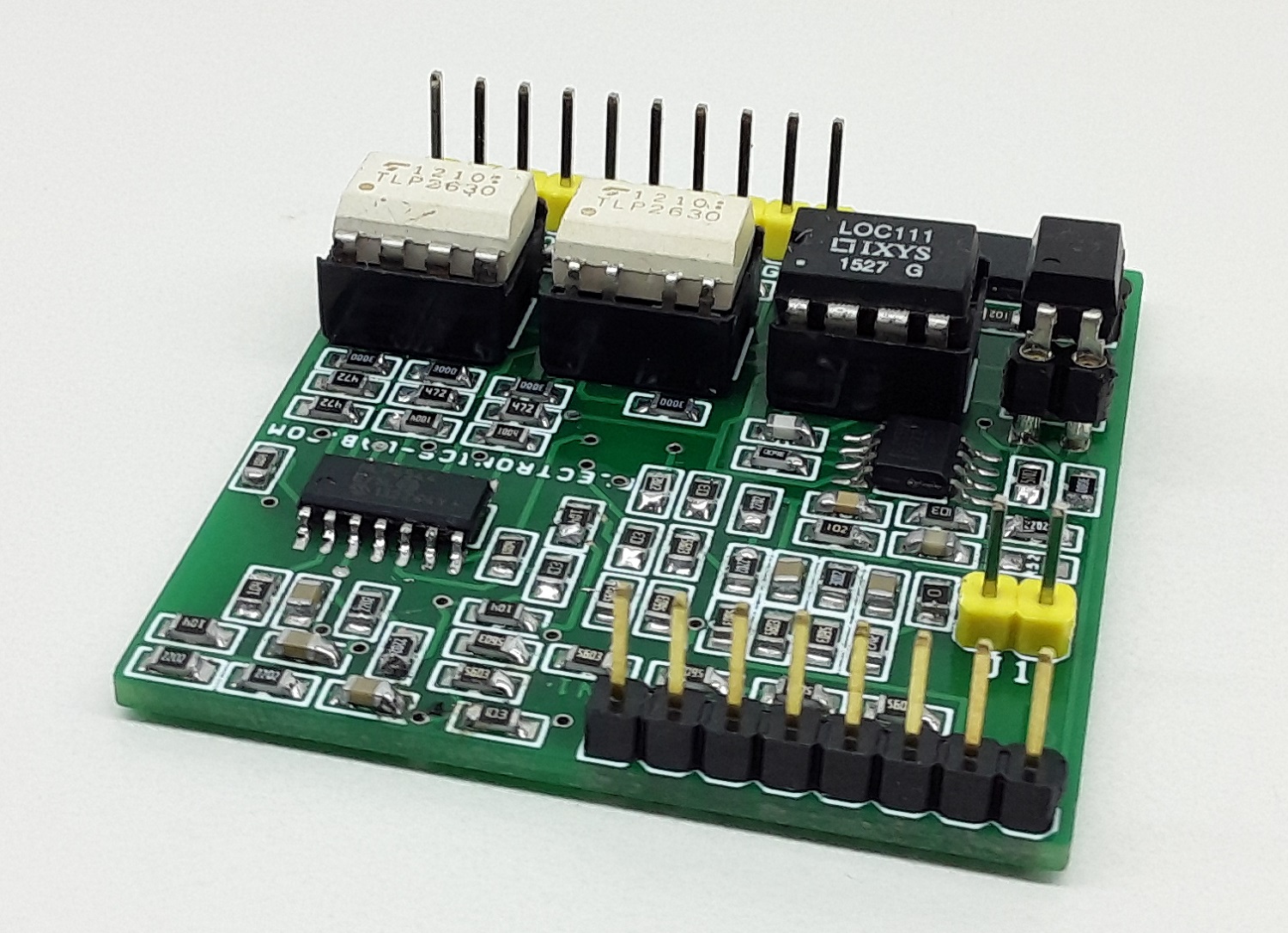
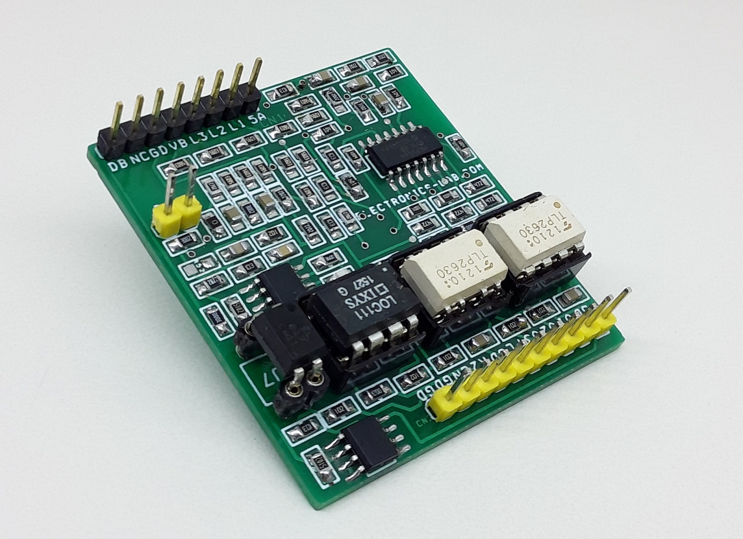
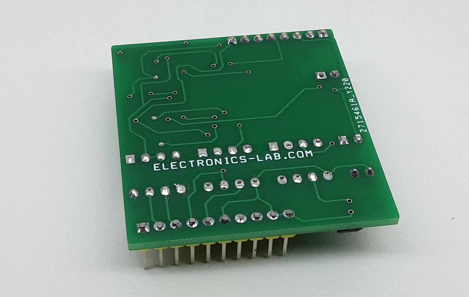
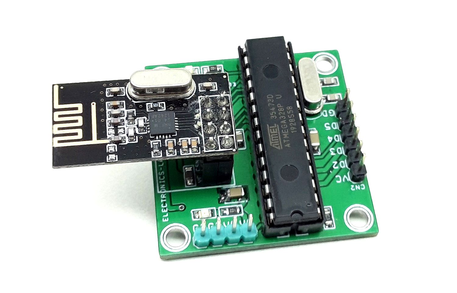
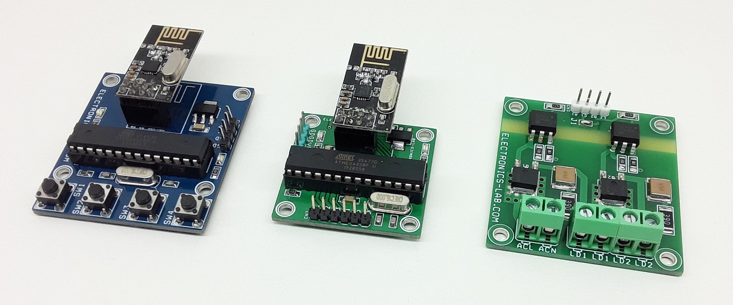
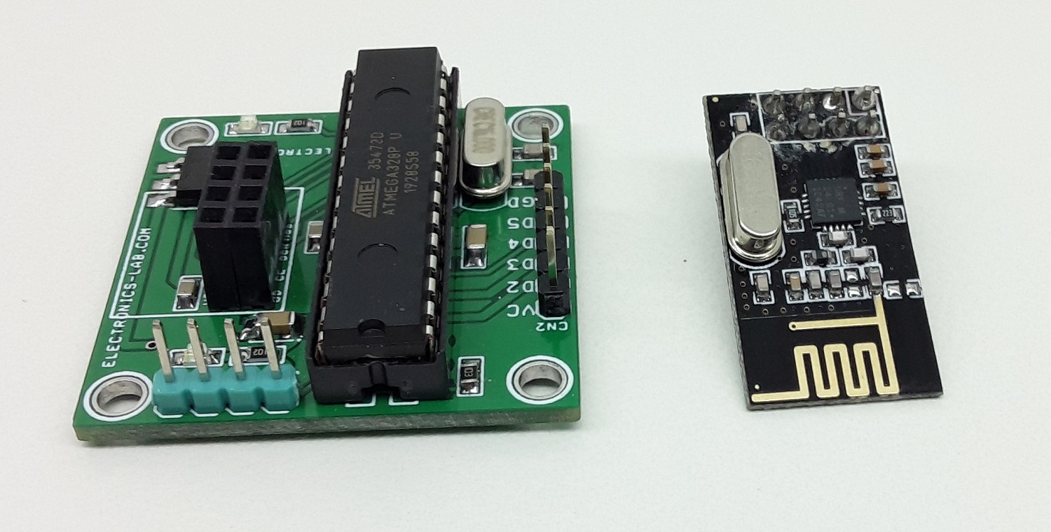
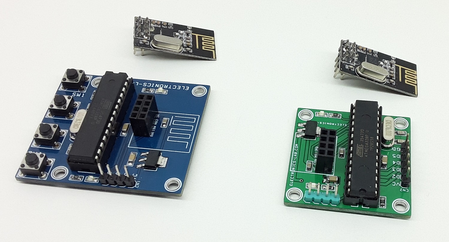
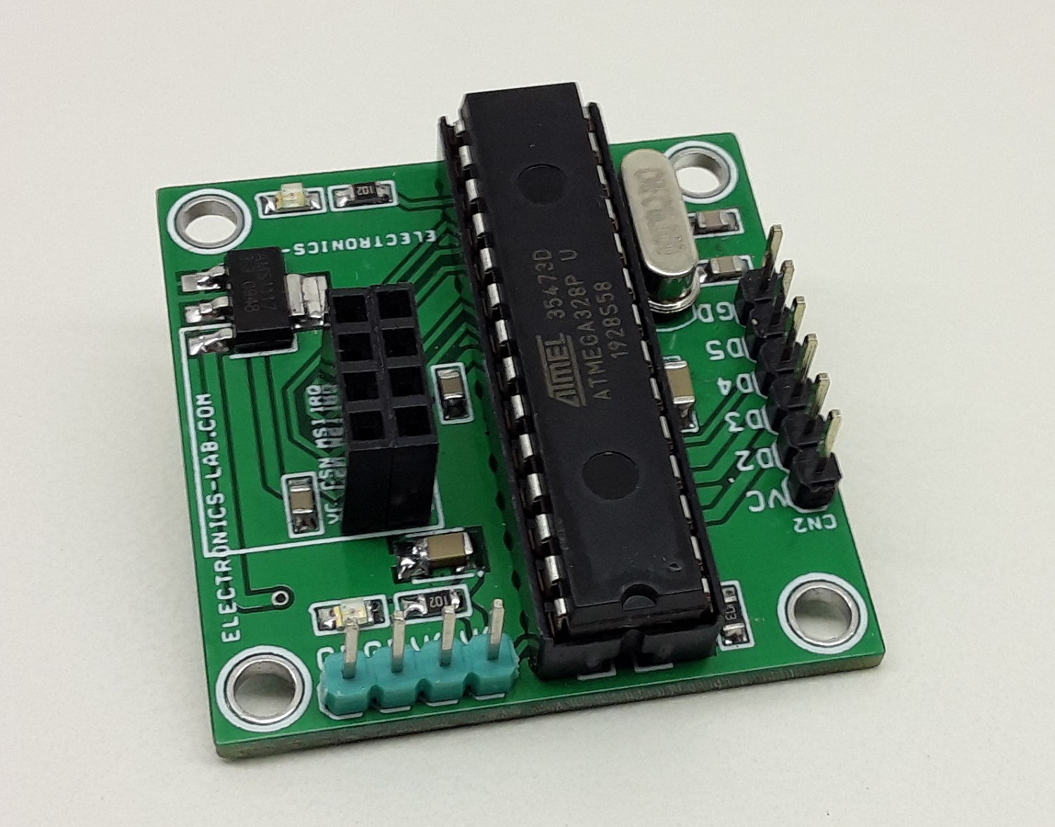
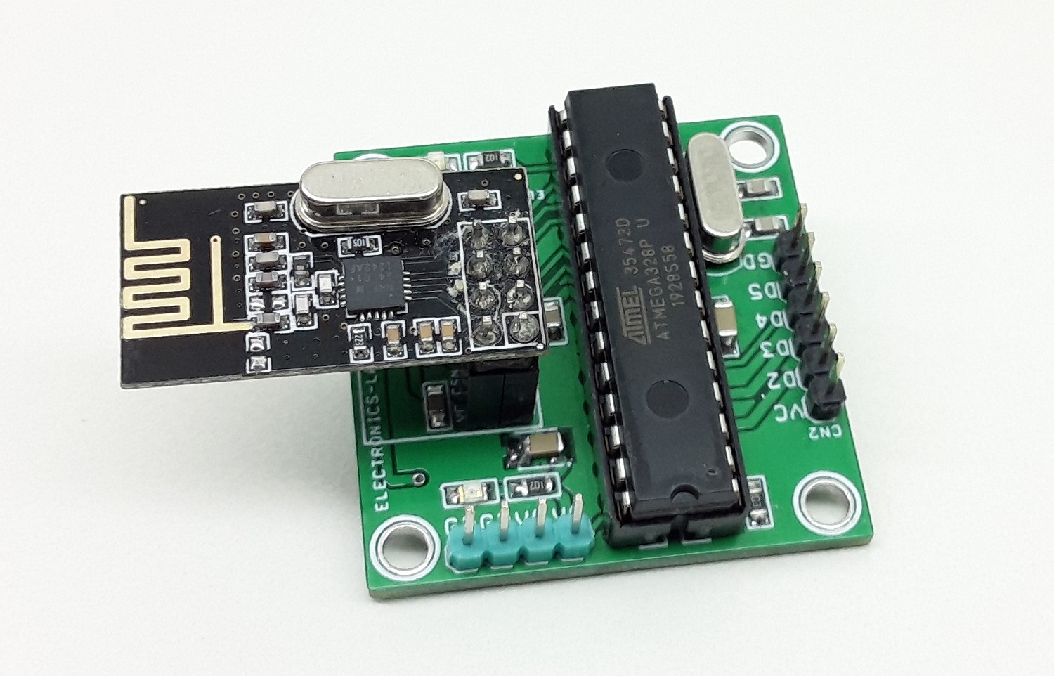
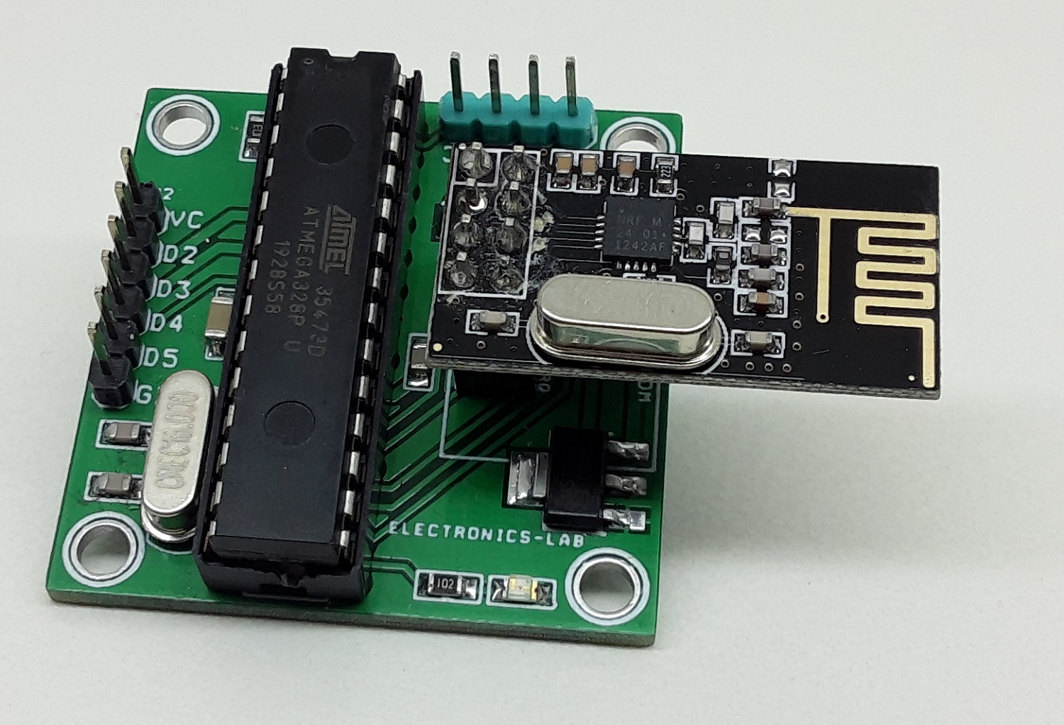
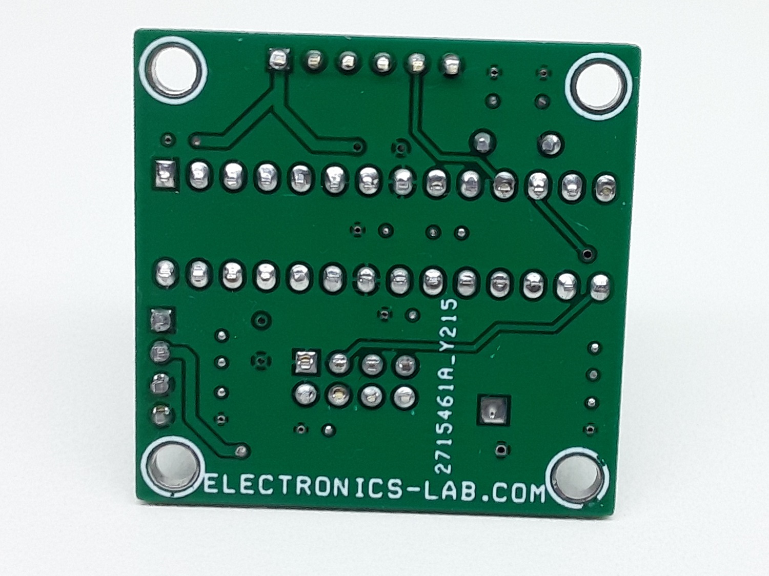
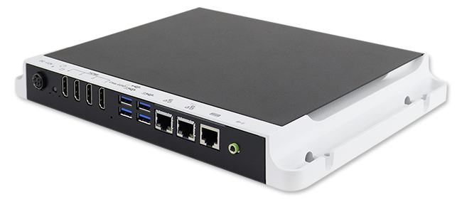
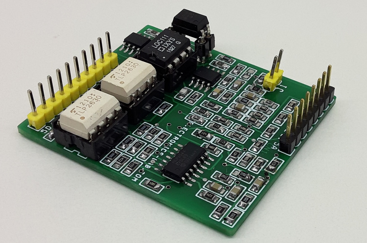
Photos