Texas Instruments TPS7A78 Low-Dropout (LDO) Linear Regulator improves the overall efficiency and standby-power in power-supplies in an easy-to-use, non-magnetic approach to AC/DC conversion. The TPS7A78 uses a capacitor-drop architecture to lower the AC source voltage before actively clamping the rectified voltage. The device then regulates this rectified voltage down to the application-specific operating voltage. The unique architecture of the device allows the standby power to be reduced to just a few 10s of milliwatts. The TPS7A78 switched-capacitor stage reduces power losses by stepping down the rectified input voltage by a factor of four and increasing the output-to-input current by the same ratio, as given by PIN ≅ POUT and VIN ≅ VOUT × 4. Compared to a traditional capacitor-drop (cap-drop) stage, this step down reduces input current, thus minimizing the value of the capacitance needed.
Electricity-metering applications, where the power supply must be reliable and magnetic tamper-proof, benefits from using the TPS7A78 because this device does not require external magnetics. This feature makes complying with IEC 61000-4-8 easier while minimizing magnetic shielding cost. The TPS7A78 also comes with a user-programmable, power-fail detection threshold that can provide an early alert to power failures and enable shutdown before complete power loss. The power-good indicator (PG) is also provided for sequencing or resetting a microcontroller.
Features
Non-isolated power solution for ≥ 18VAC RMS
Up to 75% efficiency
15mW (typical) standby power consumption
Line-voltage, cap-drop capacitor as small as 1/4th the size of linear solutions
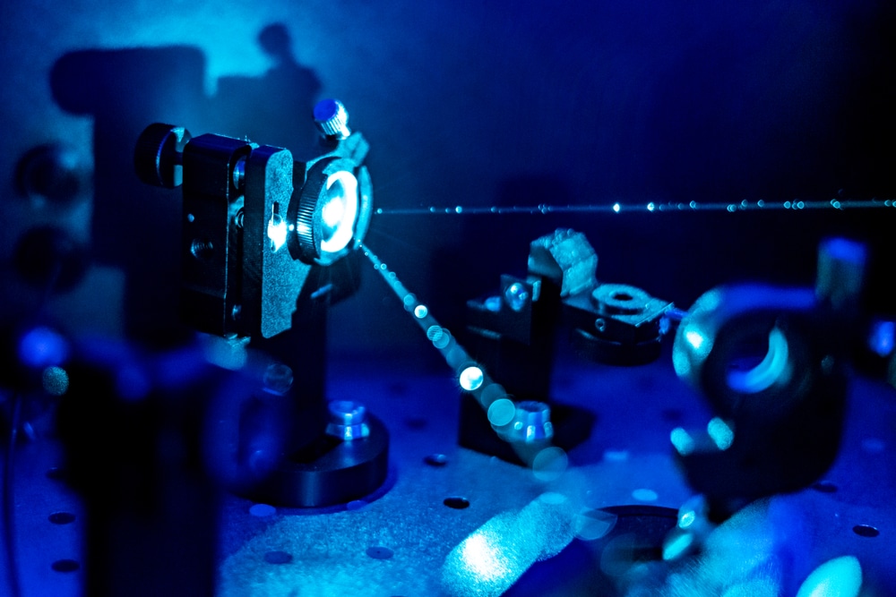
Photonics and optics are fields of engineering and physics that deal with highly complex equipment, components, and tools. The advancements in Photonics and optics are helping to form better industrial standards and help with further technological development around the world. In this article, we will discuss the applications of photonics and optics across different industries.
You may have LED lights, TVs, digital cameras, high-definition cameras, water-proof electrical gadgets, miniaturized PCBs, and more. These are all the developments made possible due to photonics and optics. Let’s dive a little deeper and explore how lasers and laser components have been vital in technological development.
Security and Defense Industry
Engineering plays a major role in developing the latest and modern equipment in the defense and security industry. From radiological, nuclear, and chemical to biological weapons, threat detection requires complete systems comprising modern photonics and optics. These electronic and highly advanced systems are key to improve defense and security.
For instance, when talking about photonics and optic electronics, optics-based sensors and components are used in surveillance technology of the finest standards. Laser technology is critical for the military since they rely on the most advanced and high-tech gadgets and assets.
Telecommunications Industry
The telecommunications industry is no different. Surely, you may know about relay towers and carrier towers. It is safe to say that the development of 5G would’ve taken a lot more years without photonics and optics developments. The optical fiber and laser components that ensure speed and lightning-fast internet connection are some of the most notable developments in the laser industry.
Energy Sustenance and Conservation Industry
We cannot live an efficient life without energy sources. It is highly important to assess and value the critical nature of optics and laser components that play a vital part in manufacturing better and more efficient energy-generating systems. When optics overlaps with photonics, a combination of materials, their chemistry, and thermal science pave the way to the generation of the latest solar modules and cells. LED-based lighting is an efficient energy conservation approach that has been possible only through the advancement of optics and photonics experts in their respective fields.
Quantum Physics and Engineering Industry
Quantum physics and engineering has laid the foundation of the next and advanced computer generation. Some of the notable achievements include navigation across environments that are GPS-blind. Moreover, other accomplishments of quantum engineering and physics have led to the development of ultra-precise and potentially the most accurate sensors and atomic clocks globally. This is all possible through the use of lasers and laser components that boast the right manufacturing techniques, high-quality material, and devices and electronics to deliver the right results.
Conclusion
Without laser technology and upgrades, most industries would still be tackling the common issues and continue using traditional technology. The expansion and innovation of photonics and optics are vital for energy conservation, medicine development, advancement in computing technology, and modern optics systems.
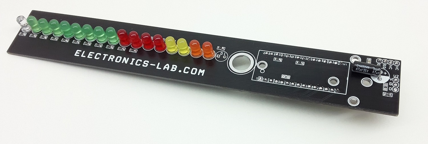
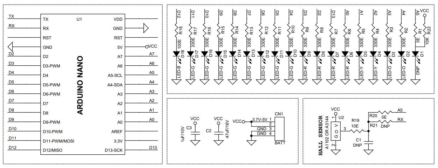
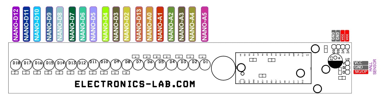
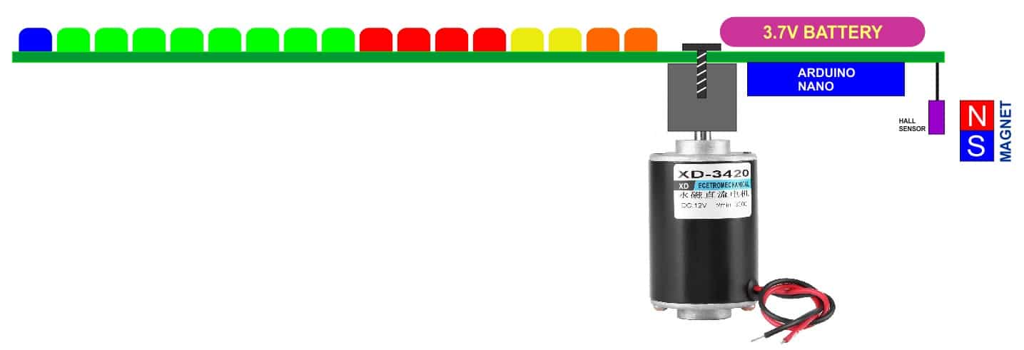
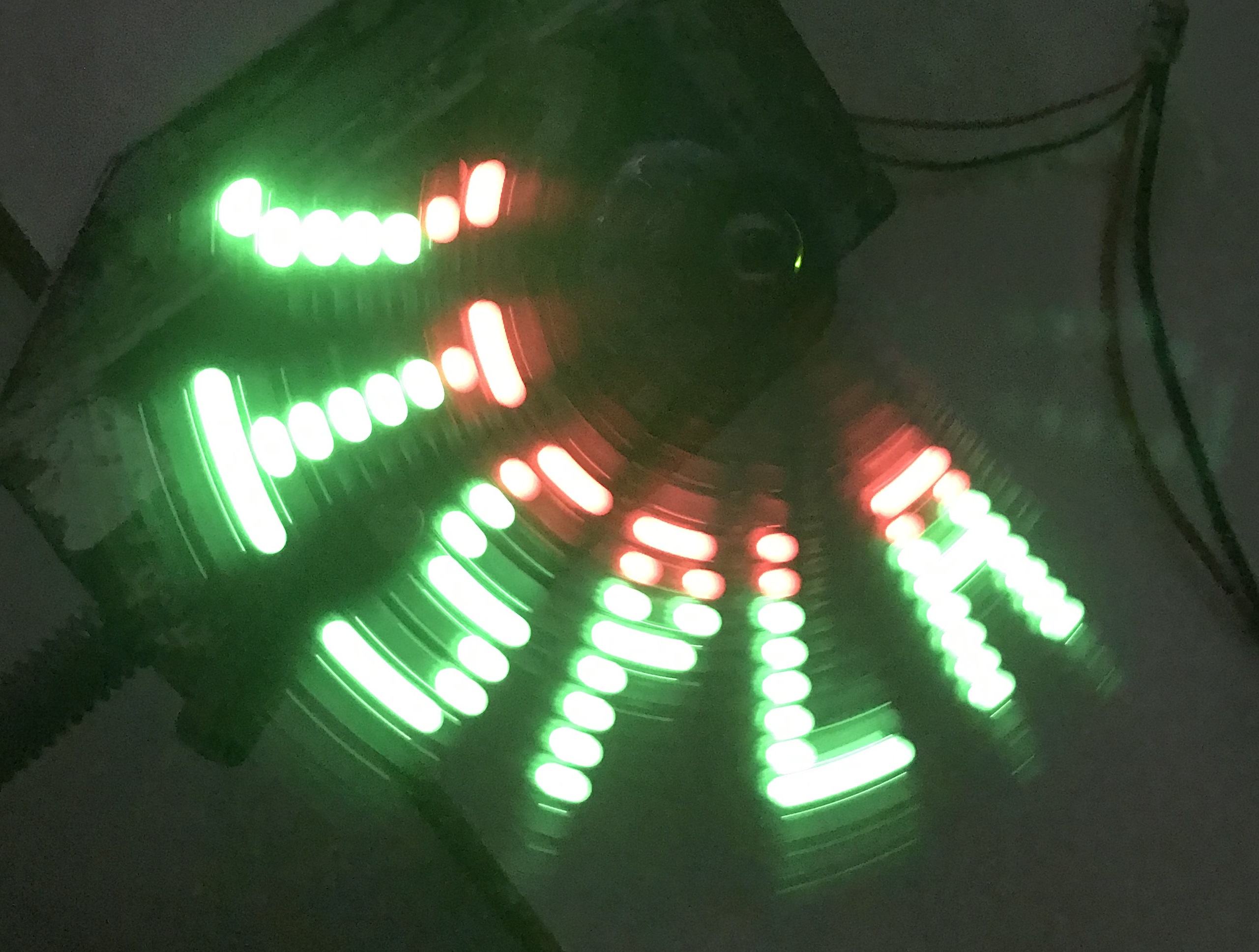
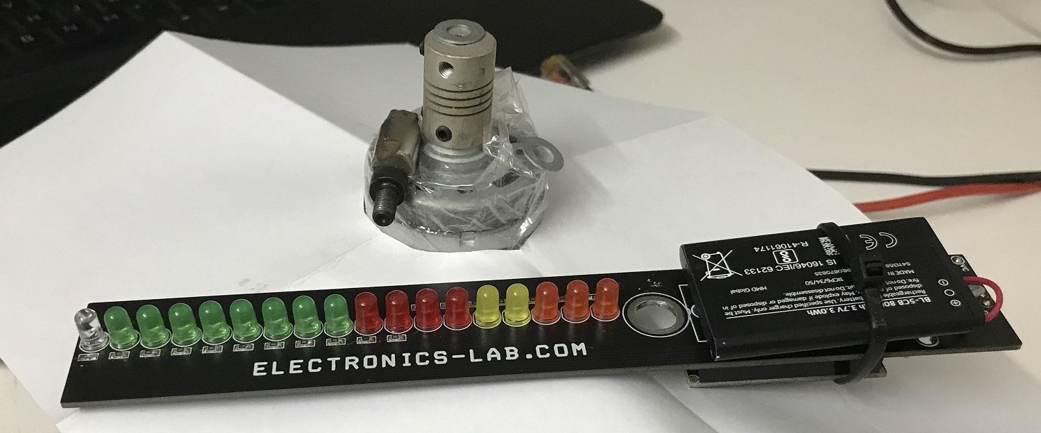
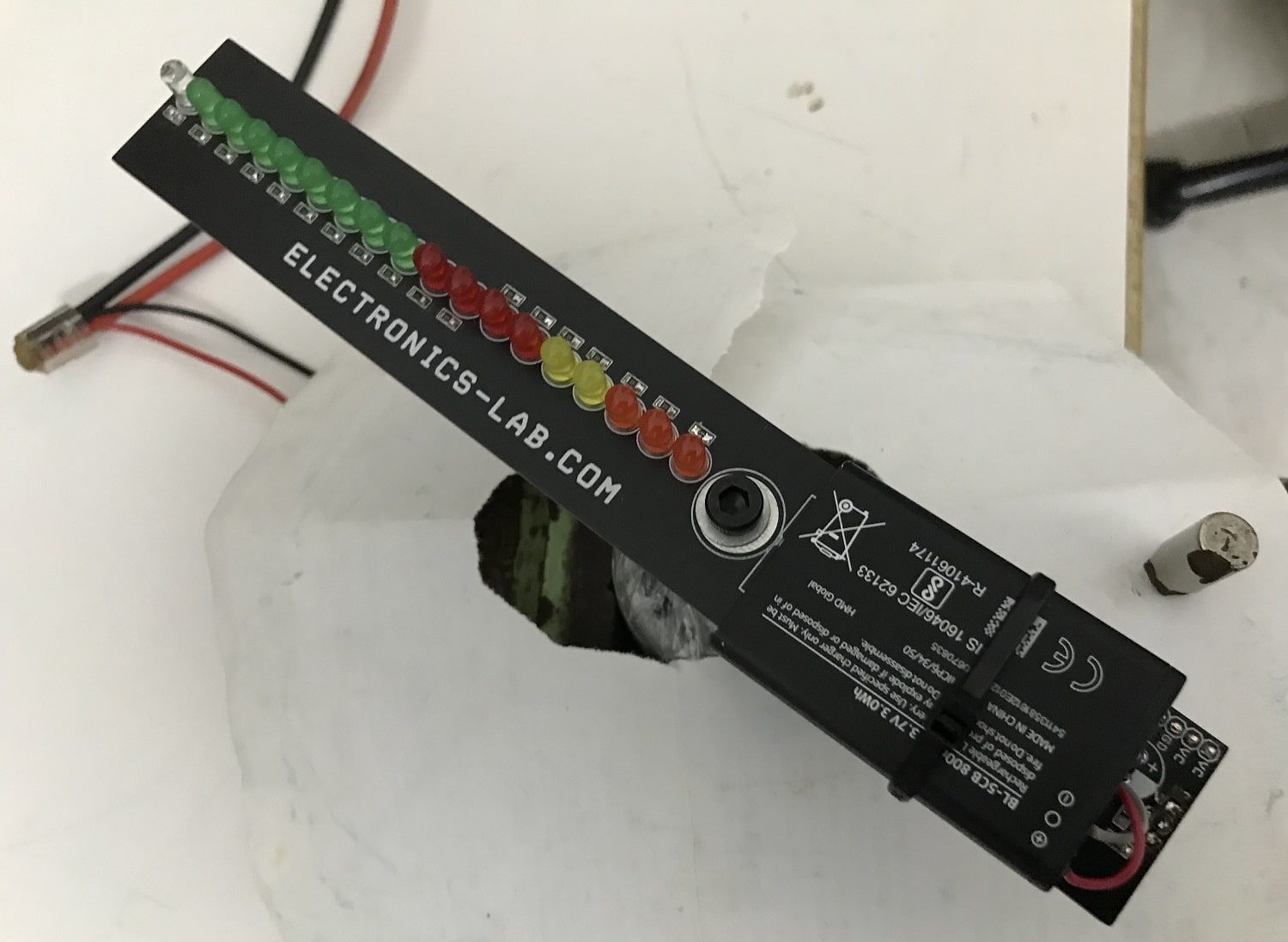
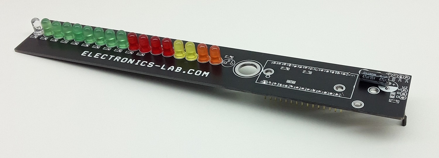
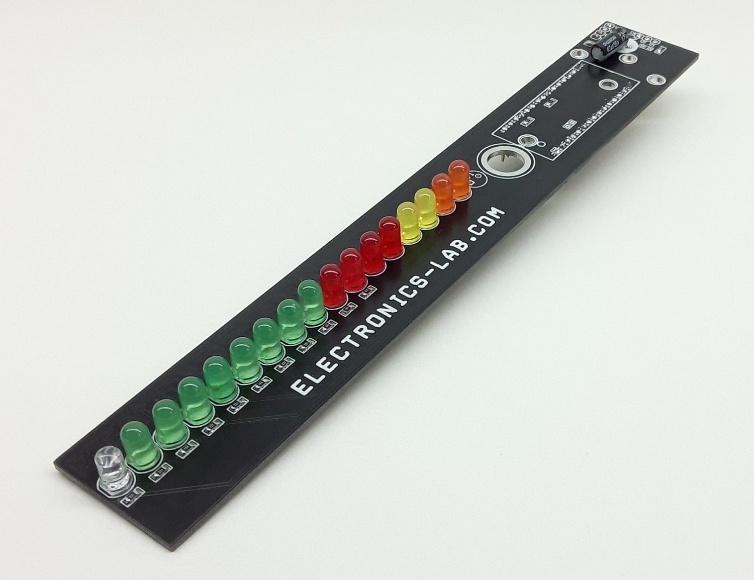
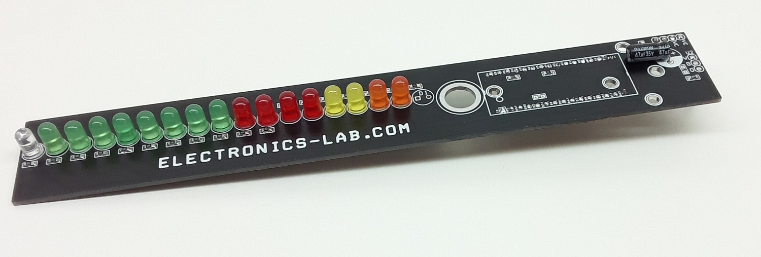
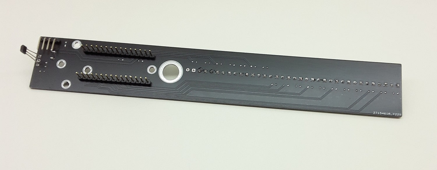
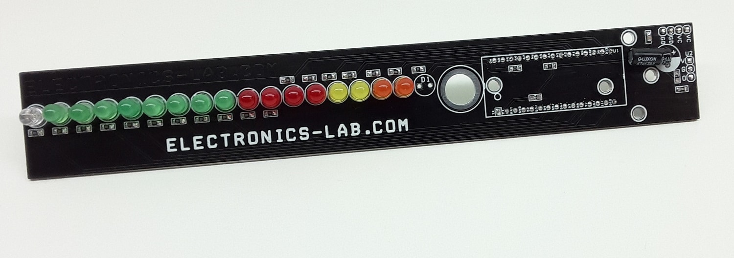
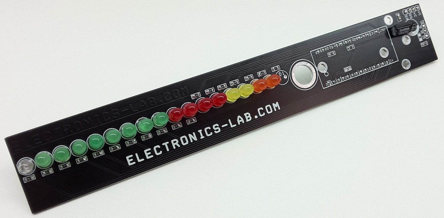
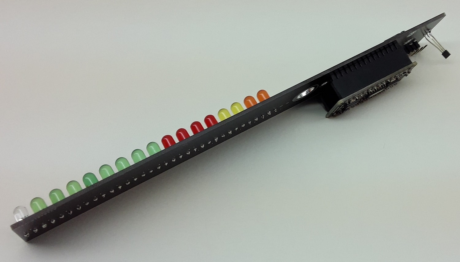
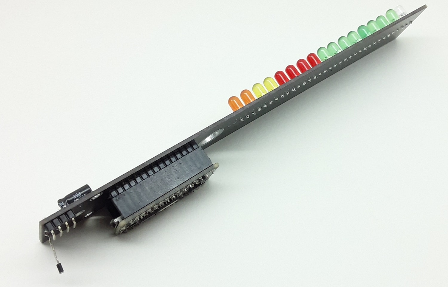
This is an easy and simple hardware to create a POV display. The hardware consists of a Hall sensor, Arduino Nano, 17 x 5mm LEDS of various colors, etc. The Hall Sensor is connected to analog pin A5 with a pull-up resistor. The circuit works with 3.7V to 5V DC and a 3.7V battery is ideal to use. The user may use as many LEDS as required. This project can also be used to create many applications such as Bar-Graph display, LED light effects. A large 8.5 mm hole is provided to mount the motor coupling. Refer to the diagram for mounting the hall sensor, motor, and magnet.
POV or persistence of vision refers to the optical illusion that occurs when visual perception of an object does not cease for some time after the rays of light proceeding from it have ceased to enter the eye. The illusion has also been described as “retinal persistence”, “persistence of impressions”, simply “persistence” and other variations.
LED D1 : This LED is optional and not installed, user may assemble this LED if the board is used for other application.
Arduino code is available to test the board. The code makes use of 6 LEDs, refer to the diagram to mount the PCB on the motor shaft, Magnet, and Hall sensor potion.
Credits: Original Author of the Arduino Code is Palak Mehta.
The NAND and NOR logical gates are most commonly termed as Universal Logic Gates as they can be used to construct all other logical functions and Boolean expressions.
As it is learned from previous articles that AND, OR, and NOT are the most basic type of logic gates. They are the most basic building blocks of any digital or logic circuit. These logic gates can be used to construct any logical function or Boolean expression involving various theorems and laws of Boolean Algebra. The logic gates which can build any other logic function or Boolean expression are classified into “Set”. These AND, OR and NOT logic gates make a “Full Set” of Universal Logical Gates as each basic logic function is performed by an individual logic gate, individually.
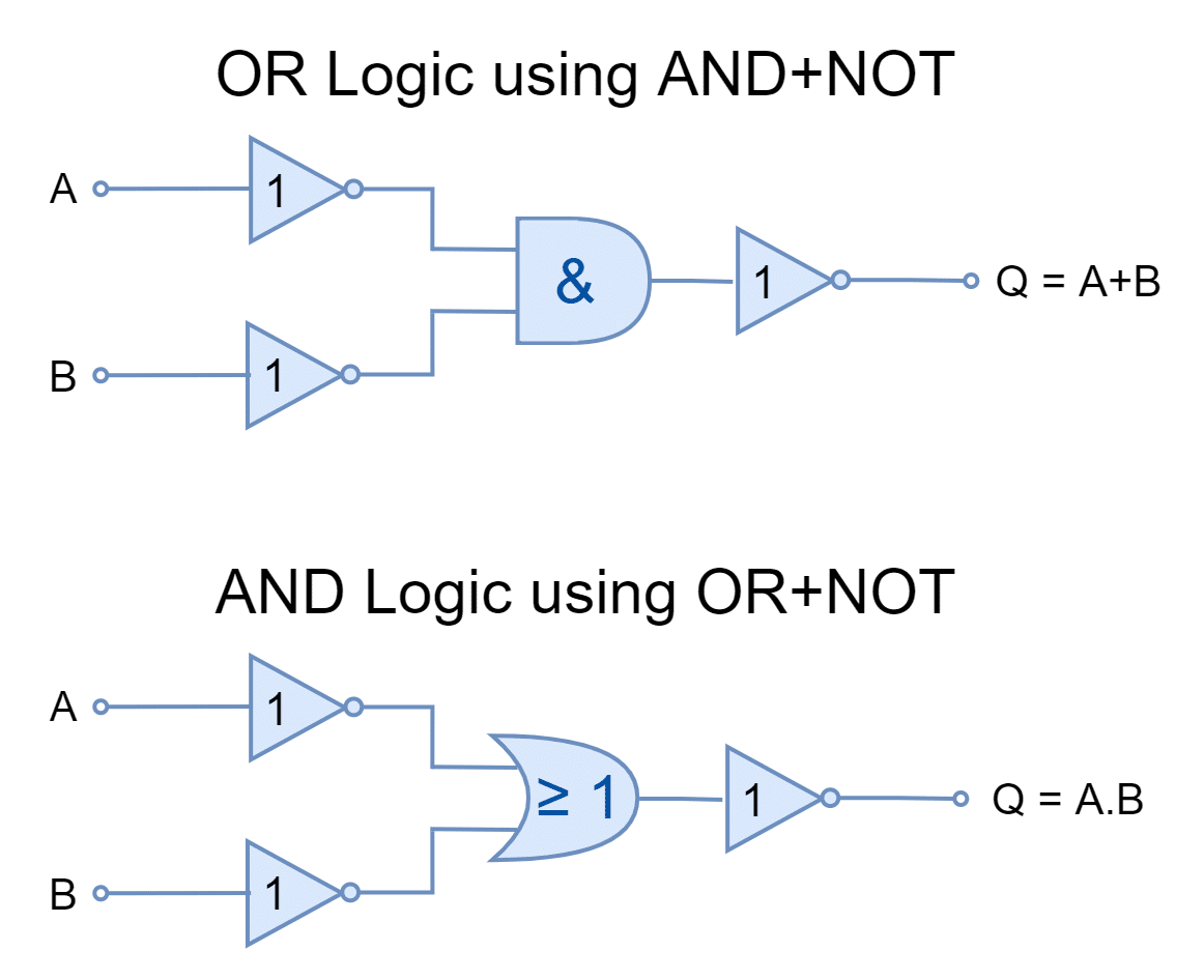
On the other hand, AND & NOT logic gates can be used to produce OR logic. Likewise, OR & NOT logic can be used to produce AND logic. Thus, AND & NOT and OR & NOT gates can also be used to produce all three basic logical operations. They are termed as a “Complete Set” and this set using two logic gates (AND+NOT or OR+NOT) can produce all three basic logic operations.
Figure 1: The OR and AND logic using AND/NOT and OR/NOT, respectively
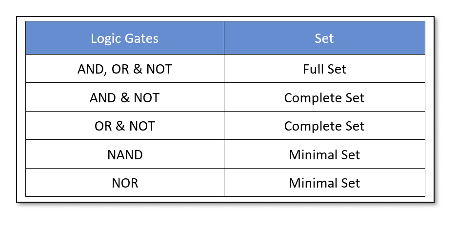
As described in previous articles, cascading of AND & NOT gates constructs a NAND logic gate. Whereas, as seen above, AND & NOT gates make a “Complete Set” to produce all three basic logic operations i.e. AND, OR, and NOT. So, ultimately, only the NAND logic gate (AND+NOT) can be used (in combinations) to produce other logic operations. Likewise, the combination of OR & NOT gates, the NOR logic gate can also be used to produce other logic operations. The NAND or NOR logic gates constitute the “Minimal Set” as by only using any of them all other logic functions or Boolean expressions can be constructed.
In the above table, five logic gate sets are listed and by using logic gates from each set complex combinational logic circuits can be constructed. Before proceeding further, let us recall the logical operations, switching characteristics and truth tables of three basic logic gates:
The Logic NOT Gate
The logic “NOT” gate, produces the inverse (NOT) of the input signal. It complements the input and produces it at the output. It does not perform any logical decision like AND & OR gates. It is denoted by a triangle having an “Inversion Bubble” at the output side. The “Inversion Bubble” represents an inversion, complement, or opposite of the incoming signal. It has a single input and single output. The cascading of another “NOT” gate will revert the signal to the original input. This double inversion constitutes a Digital Buffer that is used to amplify the input signal and/ or to isolate input and output circuits.
Figure 2: The NOT gate symbol
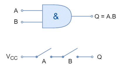
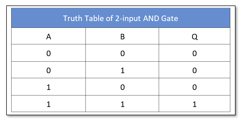
The Logic AND Gate
The logic “AND” gate performs multiplication on the digital inputs. The output of the logical “AND” gate represents the product (multiplication) of its digital inputs just like a mathematical multiplication. It is represented by a dot (.) between operands (inputs). It has two inputs and one output. The inputs of the “AND” gate can be extended by cascading the “AND” gates.
Figure 3: The AND gate symbol
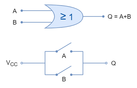
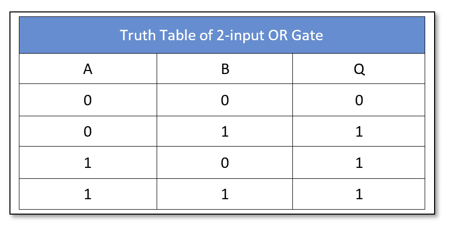
The Logical OR Gate
The Logical “OR” gate performs the addition of digital inputs. The output of the logical “OR” gate represents the summation (addition) of its inputs just lie a mathematical addition. It is represented by a plus (+) sign between the operands (inputs). It has two inputs and one output. The inputs of the “OR” gate can be extended by cascading the “OR” gates.
Figure 4: The OR gate symbol and switching logic
Now, the “Complete Sets” of AND & NOT and OR & NOT logic gates are used to construct basic logic gates.
Using AND & NOT Complete Set
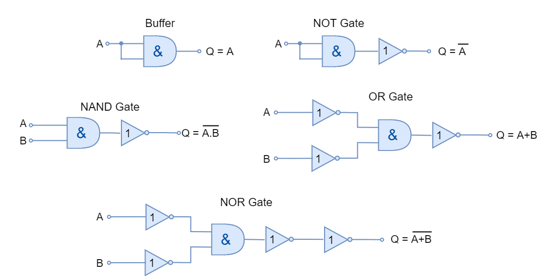
In the following figure, the basic logic gates are constructed using only AND & NOT gates. The gates constructed are equivalent of AND/ NOT set equivalent.
Figure 5: The AND/NOT Complete Set
Using OR & NOT Complete Set
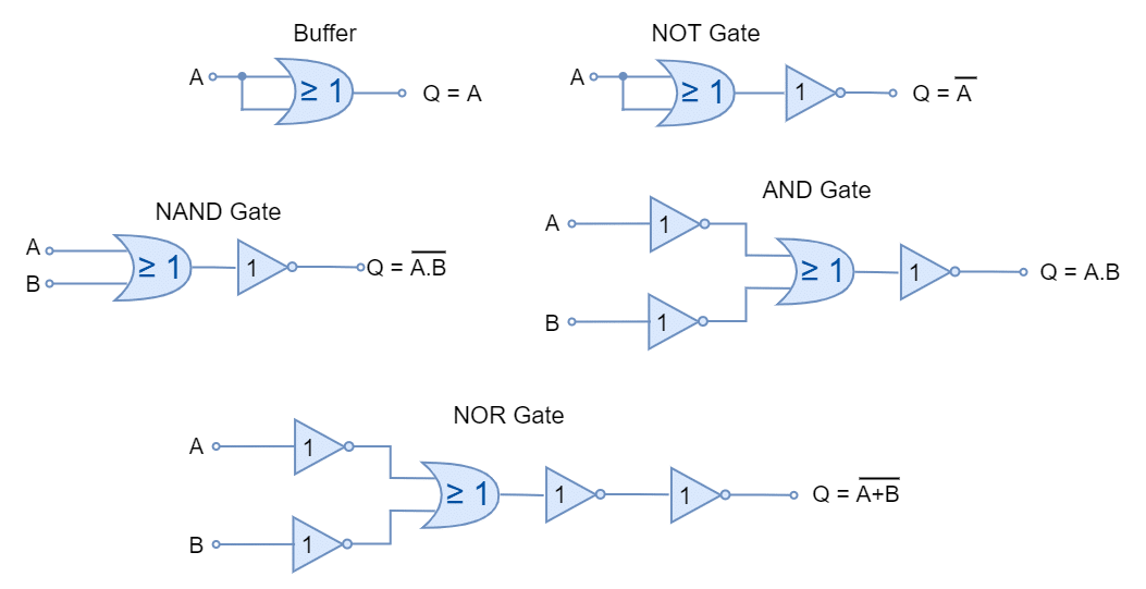
In the following figure, the basic logic gates are constructed using only OR & NOT gates. The gates constructed are equivalent of OR/ NOT set equivalent.
Figure 6: The OR/NOT Complete Set
Using AND, OR, and NOT Full Set
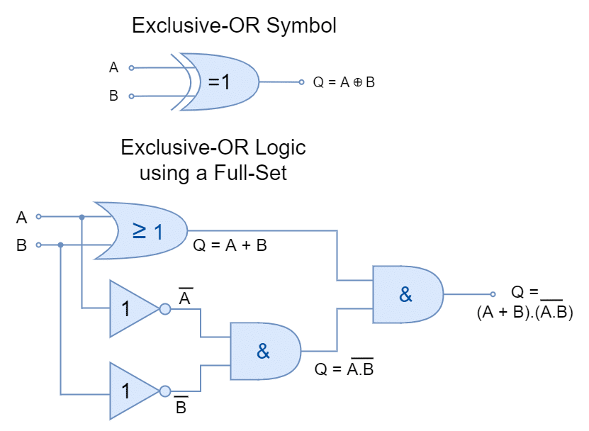
It is eminent from previous lectures that using AND, OR, and NOT (Full Set), any logic function and Boolean expression can be constructed. In the following figure, an exclusive-OR (XOR) logic gate is constructed using gates from Full Set.
Figure 7: The Exclusive-OR gate using Full Set
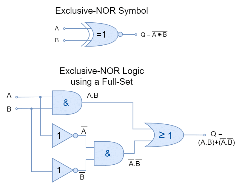
Likewise, using a Full Set, an exclusive-NOR (XNOR) logic gate is constructed in the following figure.
Figure 8: The Exclusive-NOR gate using Full Set
It is pertinent to mention here that the aforementioned Exclusive-OR and Exclusive-NOR gates are not classified as Universal Gates because they cannot produce other logic or Boolean functions.
Universal Logic Gates
The Minimal Sets of NAND and NOR gates are most commonly referred to as Universal Logic Gates. Using only NAND or NOR logic gate, any other logic function can be constructed. Using a single type of logic gate for the construction of logic function is preferable. The Full Set (AND, OR, and NOT) and Complete Sets (AND/NOT and OR/NOT) can also be used to construct logic functions but it contains different logic gates. It is not preferable to use different logic gates for the construction of logic as the same type of logic gates are usually manufactured in a single package and using different logic gates in a digital circuit would require different IC packages. Comparatively, using NAND or NOR only requires only a single IC package such as using 74LS00 (quad 2-input NAND TTL) or 74LS02 (quad 2-input NOR TTL) IC package a number of logic functions can be produced.
Using NAND Gates
In the following figure, other logic functions are constructed using only NAND gates. The commercially available 7400 TTL (74LS00 or 74HC00) quad 2-input NAND IC package contains four individual NAND gates. The four NAND gates of the 74LS00 IC package are used to produce all other logic functions.
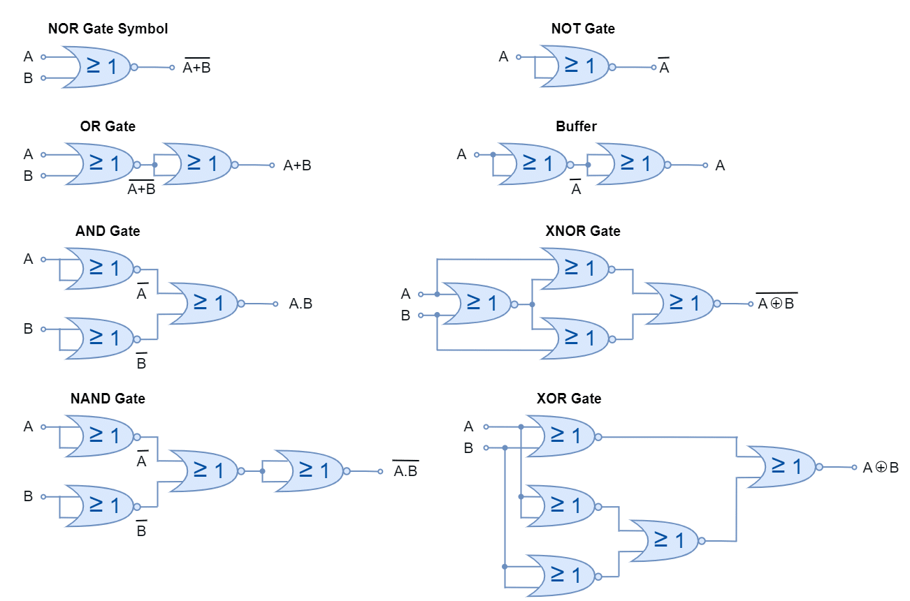
Figure 9: The NAND gate logic circuits
Using NOR Gates
In the following figure, other logic functions are constructed using only NOR gates. The commercially available 7402 TTL (74LS02 or 74HC02) quad 2-input NOR IC package contains four individual NOR gates. The four NOR gates of the 74LS02 IC package are used to produce all other logic functions.
Figure 10: The NOR gate logic circuits
It is clear from the above figures that the construction of Exclusive-OR gate requires four (04) NAND or five (05) NOR gates. The Exclusive-OR (XOR) gate produced from NAND gates is more efficient compared to the one constructed from NOR gates.
Conclusion
The Universal Logic Gates are the ones that can produce any other logic or Boolean expression.
The AND, OR, and NOT are the basic gates and can produce any logic or Boolean expression. The logic gate(s) which can produce any other logic are grouped as a “Set”. These AND, OR, and NOT basic gates constitute a “Full Set”.
The AND+NOT and OR+NOT gate sets can also be used to produce any other logic and these gate sets make a “Complete Set”.
The NAND and NOR logic gates constitute a “Minimal Set”’ and are commonly termed as Universal Logic Gates. The NAND or NOR gate individually or in combination can produce any other logic function or Boolean expression.
Commercially available Quad 2-input NAND (74LS00) and Quad 2-input NOR (74LS02) IC packages contain four individual gates and can produce all other logic functions.
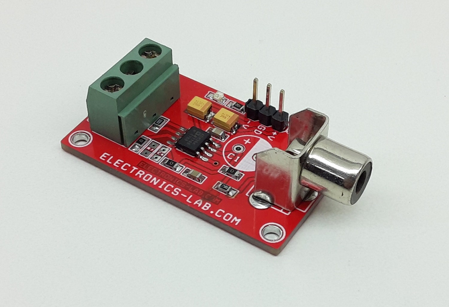
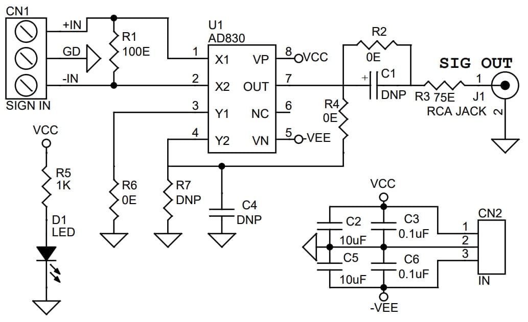
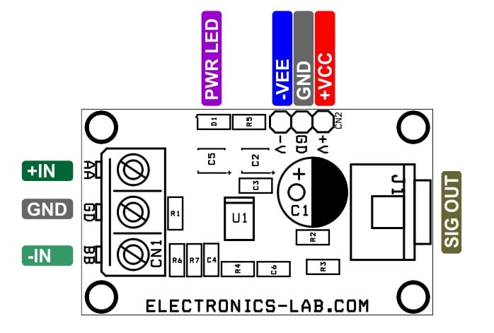
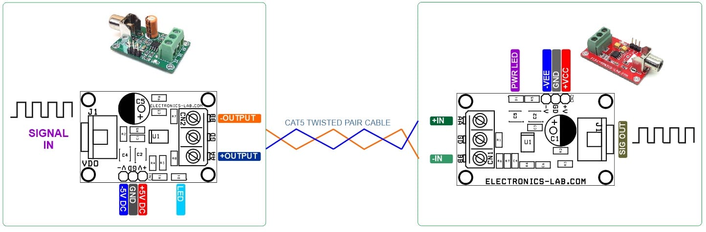
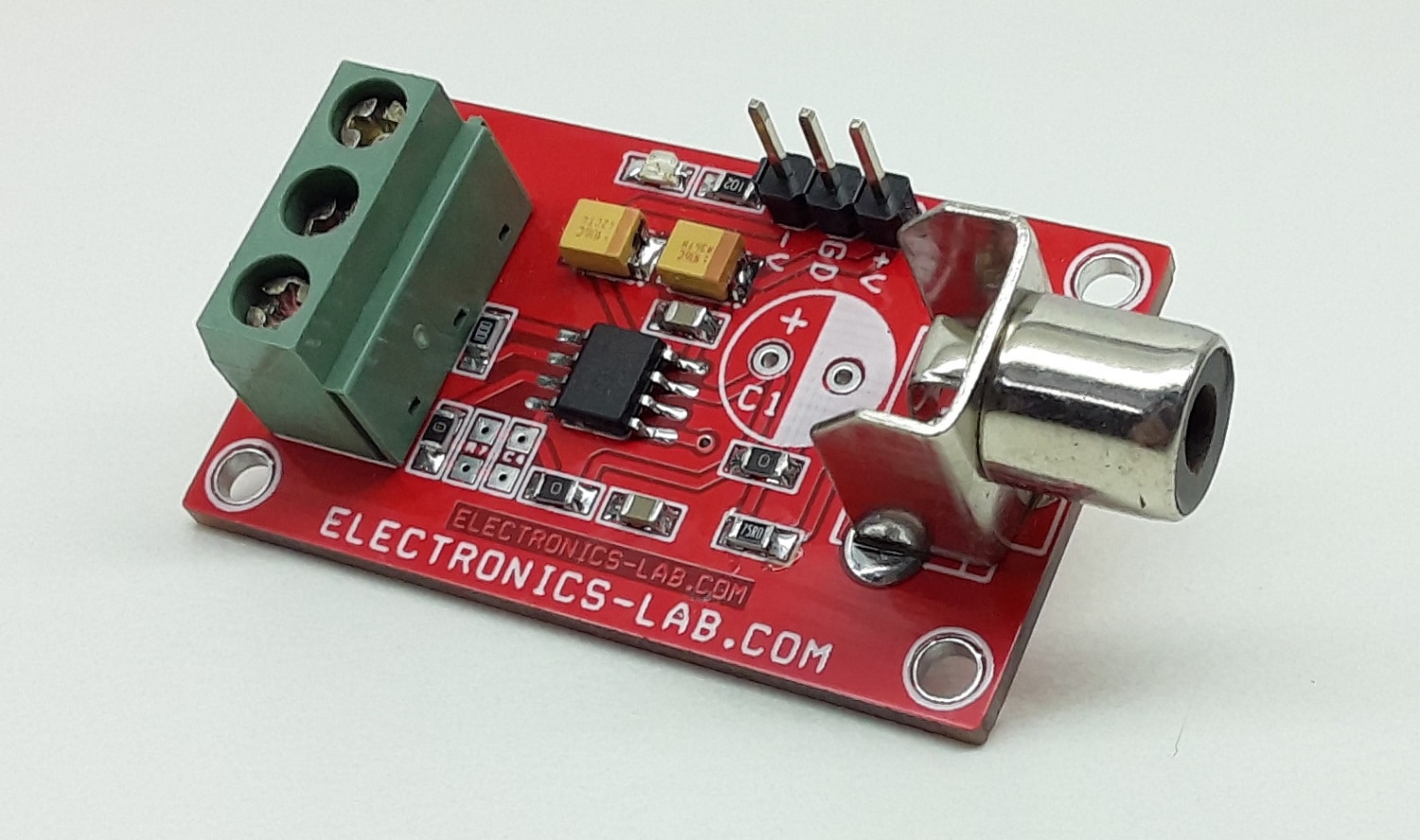
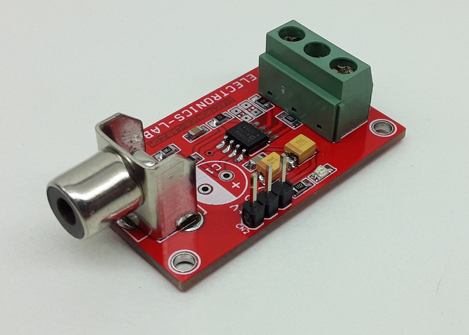
The circuit presented here is a high-frequency differential line receiver amplifier that has excellent common-mode rejection at its inputs. The project is an ideal solution for a receiver of a digital signal or video signals that are transmitted over long distances on twisted-pair cables like CAT5. Category 5 cables are very common in office settings and are extensively used for data transmission. These cables can also be used for the digital signal or analog transmission of signals such as video. These long cables pick up noise from the environment they pass through. This noise does not favor one conductor over another and therefore is a common-mode signal. A receiver that rejects the common-mode signal on the cable can greatly enhance the signal-to-noiseratio performance of the link. This project is tested with 100Hz to 1Mhz square wave signal, however, it can support higher frequency.
Note: The above Transmitter (Line Driver) is compatible with this line receiver, but one change is required, replace C5 with a direct jumper for digital input, since it was initially designed for video input.
Transmitter and receiver work in tandem to convert a digital signal or Composite Video signal to a differential signal and extend it over a single CAT-5 cable pair. Line driver and line receiver projects can be used to transmit and receive digital signals over 300 meters of category 5 (CAT-5) cable. The cable has an attenuation of approximately 20dB at 10Mhz for 300 meters.
Features
Operating Supply Dual +5V/-5V (+/-5V) @ 80mA
Input and Output Voltage Level 500mV to TTL
Compact Solution for Digital Signal Transmitter and Receiver over CAT-5 Twisted Cable
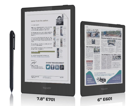
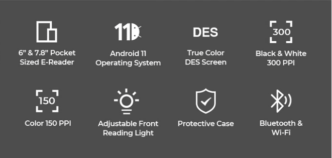
A campaign has been launched on Kickstarter for TopJoy Butterfly, which is a full-featured, ultra-portable color e-book reader with 6 and 7.8-inch screen size options. TopJoy Butterfly is a versatile reading pad that supports different file formats, and popular reading apps, making your reading experience effortless. Powered by the Android 11 operating system, it is equipped with a true color DES screen, enables 300 PPI for black & white content, and unmatched 150 PPI for color. It also features a stylus with an eraser. TopJoy enables you to read, sketch, and take notes while giving you the full-color paper-like reading and writing experience. It is portable, lightweight and compact, and an ideal pad for everyday use.
TopJoy features a true color DES screen, which enables it delivers up to 1404*1872px high resolution, and a better reading experience in both monochrome and color, presenting 300 PPI for a sharp and crisp display of black & white content. TopJoy Butterfly’s Android 11 OS enables you to have access to basically all book resources on the internet. TopJoy supports virtually any eBook format including EPUB, FB2, MOBI, RTF, PDF, TXT, and other reading apps.
TopJoy Butterfly e-reader comes in 6” and 7.8“ inch sizes options, weighing at just 185g and 315g in respectively. They are both ultra-portable, compact, and both options come with a protective case.
The 7.8-inch TopJoy Butterfly e-reader has a stylus, which enables you to take notes on PDF, EPUB, TXT, and other ebook files. It also supports Wi-Fi and Bluetooth data transfer, so you can move or share your files. The Note feature of TopJoy 7.8″ e-reader enables you to make sketches or leave your handwriting with the 4096-level stylus with an eraser.
TopJoy Butterfly greatly reduces eye fatigue and strain due to its adjustable built-in reading front light and the diffuse reflection technology inside. Also, its glare-free DES screen doesn’t reflect unwanted light toward your eyes. Another good feature of TopJoy Butterfly is its built-in noise-canceling microphone & BOX speaker, which are perfect for quiet reading sessions before bed while listening to an audiobook, it is also ideal for nighttime stories with your kids.
When it comes to power, TopJoy offers a 3.8V 1500mah/3200mah battery (6 inch/7.8 inch). It provides up to 35 or 70 days standby time (6 inch/7.8 inch) before you have to recharge it, depending on which model you’re using. TopJoy Butterfly is embedded with a 1.8GHz 4 Core processor and 2GB RAM & 32GB ROM, giving it fast speed and quick response.
For more information about this project, visit the campaign page on Kickstarter.
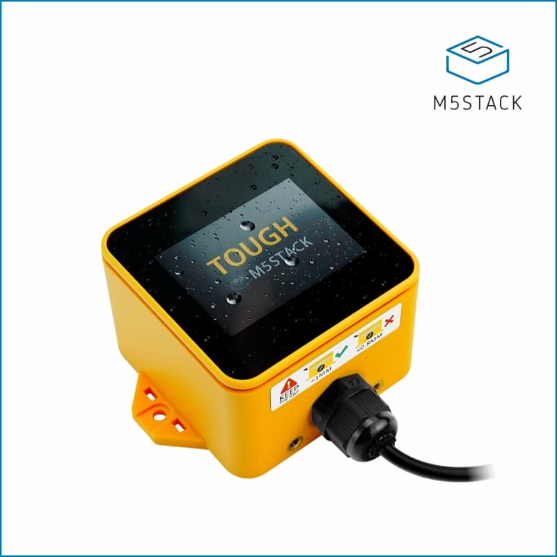
M5Stack just expanded its M5 controller series with the introduction of the M5Stack TOUGH. Incorporating ESP32 Wi-Fi & Bluetooth MCU and full coverage, The M5 TOUGH operates at frequencies up to 240 MHz include 8M PSRAM with 16M FLASH memory, Each M5 TOUGH integrates 2 inches LCD capacitive touchscreen that is sensitive to the human touch. The low-power M5 TOUGH is ideal for Industrial control and Smart buildings which require outdoor node data acquisition.
BEST-IN-CLASS UV resistant enclosure design protection: Water-resistant with an o-ring sealing contains Waterproof M12 Connectors can complete against solid objects, dust, sand, dirt. A variety of installations such as Screw/Rolled strip/Magnetic/Adhesive Back.
HIGH INTEGRATION: AXP192 Power management with HY8563 RTC allows M5 TOUGH to provide advanced low power techniques. M5 TOUGH comes with 2 inches LCD capacitive Multi-touch screen,1W/NS4168 I2S speaker, TF card slot. Delicate RF circuit delivers robust and consistent wireless communication.
STRONG EXPANDABILITY: Programable Expansion Board 3x Grove Interface.Effortless access to M5Stack’s hardware and software ecosystem: rich sensor extensions. M5 TOUGH is supplied from 12v->5V flexible DC/DC converter with RS485 Converter Circuits.
LOW-CODE DEVELOPMENT: M5 TOUGH supports UIFlow graphical programming platform, scripting-free, cloud push; and fully compatible with Arduino, ESP32-IDF, and other mainstream development platforms. Executing Dual-core processor on FreeRTOS to run multiple tasks for better performance.
Note: Please DO NOT immerse the enclosure in water. There is no protection from immersion.
Product Features
ESP32-D0WD-V3
16MB Flash + 8MB PSRAM
Waterproof and Dustproof
UV resistant enclosure design protection
2 inches LCD capacitive Multi-touch screen
Advanced low power techniques: Wake Up with an RTC Alarm Clock
Integrated with 12v->5V flexible DC/DC converter. Flexible power supply
A community-supported development platform for developers and hobbyists.
Only 10 days left until the winners are announced!
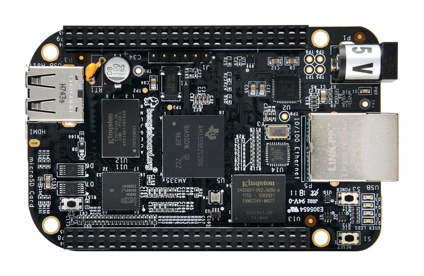
As an existing subscriber you have a chance to win this giveaway; BeagleBone Black development board, an affordable, community-supported, open source development platform designed to offer a practical and cost effective solution for makers seeking to run more advanced projects that require connectivity.
For an additional entry to win, simply follow oemsecrets.com on LinkedIn and share the link for this giveaway before midnight 17th October 2021.
BeagleBone Black is a community-supported development platform for developers and hobbyists. Boot Linux in under 10 seconds and get started on development in less than 5 minutes with just a single USB cable.
We’re pleased to announce the 2 winners of the BeagleBone Black from @beagleboardorg in partnership with @Farnell_Avnet are “Rini S.” & “Brian B.”. We’ll be in touch with you via email to get your shipping details. Congrats to both of you & thanks to everyone who entered #Winnerspic.twitter.com/w014Ej04Oa
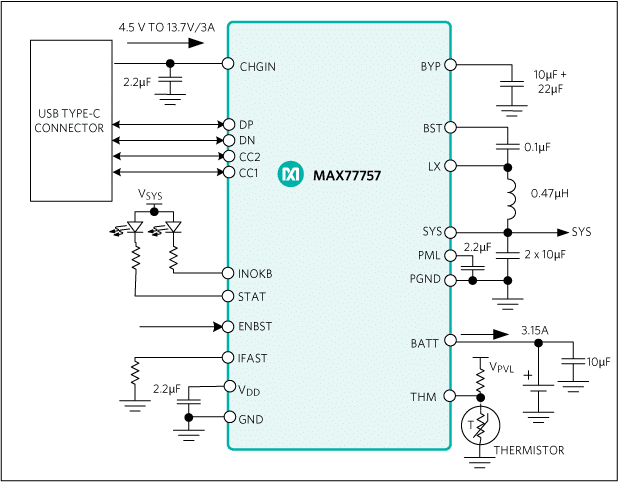
Maxim Integrated MAX77757 USB Type-C® Autonomous Charger is a standalone 3.15A device with JEITA for 1-Cell Li-ion/LiFePO4 batteries that supports reverse boost capability. The MAX77757 charger operates from a 4.5V to 13.7V input voltage range and has a maximum input current limit of 3A. This IC implements the Adaptive Input Current Limit (AICL) function. This AICL function regulates the input voltage by reducing input current to prevent the weak adapter’s voltage from collapsing or folding back. The USB Type-C Configuration Channel (CC) detection pins on the MAX77757 IC enable automatic USB Type-C power source detection and input current limit configuration. The MAX77757 IC offers reverse-boost capability up to 5.1V and 1.5A that can be enabled with the ENBST pin.
The MAX77757 autonomous charger is equipped with a Smart Power Selector™ and a battery true-disconnect FET. These equipped devices control the charging and discharging of the battery or isolate the battery in case of a fault. The MAX77757 IC is offered in several variants to support Li-ion batteries with various termination voltages from 4.1V to 4.5V. This charger comes with a 3.6V termination voltage option for LiFePO4 batteries. The MAX77757 IC is available in 3mm x 3mm dimensions, 0.4mm pitch, and 24-lead FC2QFN package. Typical applications include Mobile Point-of-Sale (mPOS) terminals, portable medical devices, wireless headphones, GPS trackers, charging cradles for wearable devices, and power banks.
Features
Up to 16V protection
6A discharge current protection
No firmware or communication required
Integrated USB detection:
Integrated CC detection for USB Type-C
Integrated BC1.2 detection for legacy SDP, DCP, CDP, and DCD timeout
Integrated USB detection for common proprietary charger types
Automatic input current limit configuration
Safety:
Charge safety timer
JEITA compliance with NTC thermistor (MAX77757J)
HOT/COLD stop charging with NTC thermistor (MAX77757H)
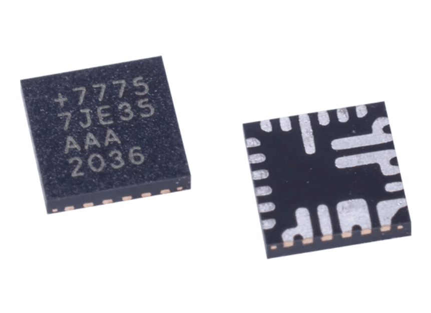
Extended-temperature-range voltage reference ICs for automotive and industrial applications require low drift, high reliability, and high performance. Microchip Technology has announced the release of a high-precision voltage reference (Vref) IC that meets these needs at a cost-effective price. The new MCP1502 is an AEC-Q100 Grade 1 (-40 to 125 °C operating temperature range) automotive-qualified Vref with a maximum temperature coefficient of 7 ppm/°C.
“Microchip looked at the top four aspects that customers were requesting in a Vref and made a product that combines high reliability, small package size and high performance at a very cost-effective price,” said Fanie Duvenhage, Vice President of Microchip’s Mixed-signal and Linear Devices business unit. “This combination of features at this price is unmatched by competitors, especially when you add our experience in serving customers in the automotive and aerospace industries who require robust products for harsh environments.”
The MCP1502 is based on the already-proven MCP1501 Vref architecture, which has been in the market for more than five years. Packaged in a small six-lead SOT-23, the MCP1502 is an ideal choice for a wide variety of industrial, automotive and aerospace applications that require a high level of reliability. Microchip’s MCP150x (MCP1501 and MCP1502) devices are perfect companions to Microchip’s families of microcontrollers, ADCs and DACs, offering multiple voltage options for creating total system solutions that are suitable for a wide variety of applications that require stable, accurate and repeatable data conversion. The MCP1502 is available in most popular voltage level options from 1 to 4 V.