WIO Lite AI – an Stm32h725a Cortex-m7 Board for AI Vision Applications

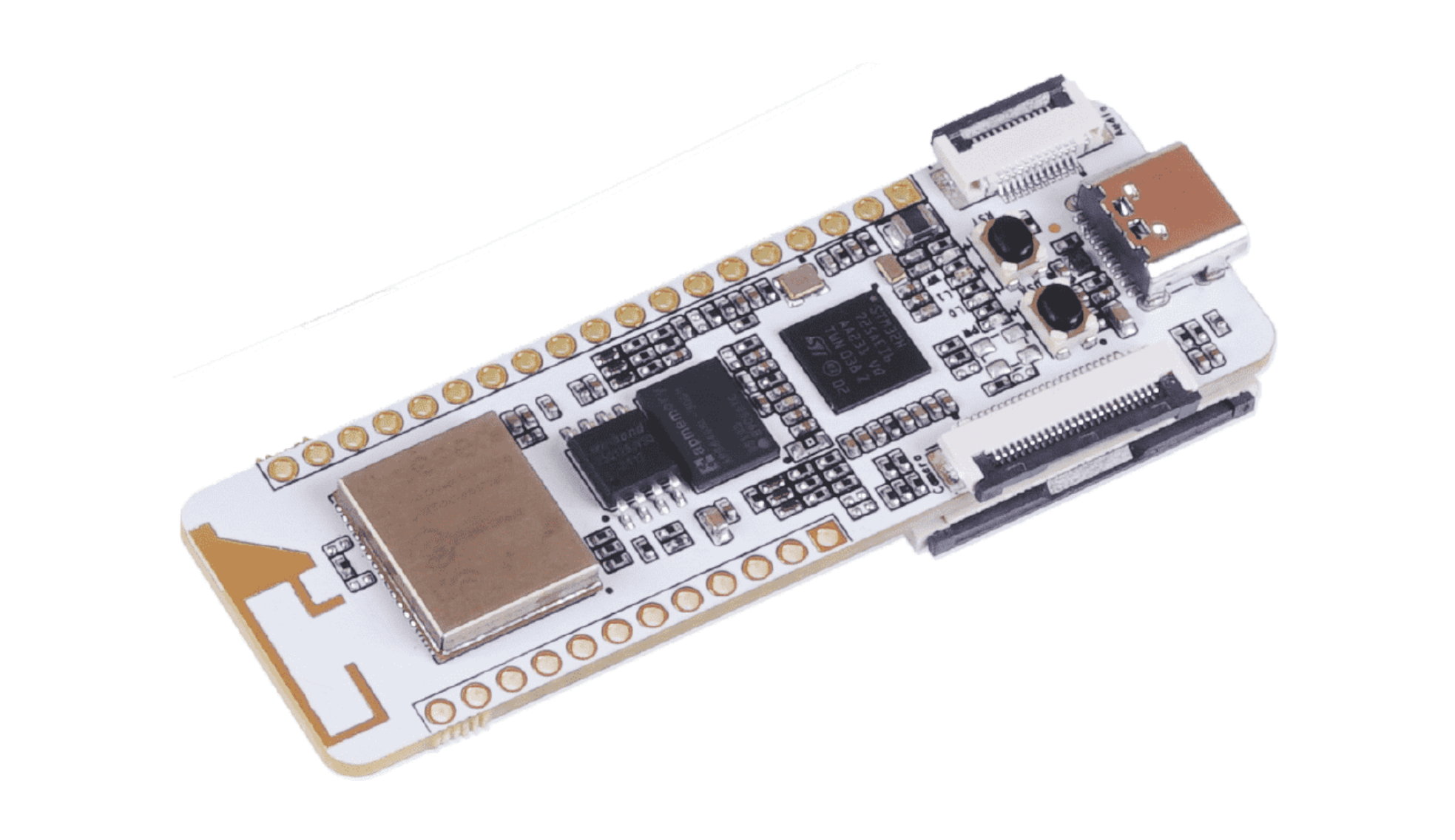
With great advancement in technology, several development boards have been designed to fit specific needs, such as AI vision applications. The Wio Lite AI is one of such technological breakthroughs. Wio Lite AI is part of the  “Wio Lite” microcontroller series and is designed by Seeed Studio. Some of its features are its dual-band WiFi and Bluetooth module, as well as camera and display interfaces specifically tailored for AI vision applications.

Being an improvement to previous Wio Lite development boards, it offers better processing power for computer vision or other applications, as well as an impressive 8MB PSRAM (from AP Memory), a 16MB SPI NOR flash, and a dedicated MicroSD card slot for storage, 12-pin FPC connector for audio and a 5V/3A power supply via USB Type-C port.

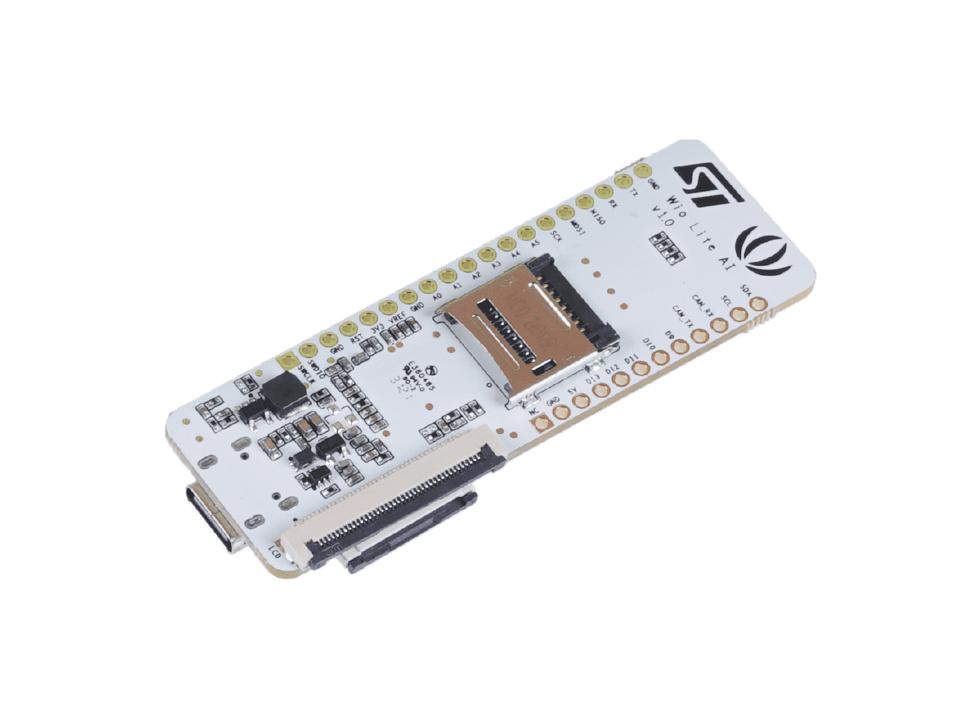
With the 40-Pin FPC port for LCD RGB565 or RGB888 and one 24-Pin FPC port for a DCMI camera on this board, WIO LITE AI is cost-effective for vision projects. It also has enough ports and pins for expansion such as 6 analog pins, 14 digital pins, 1x I2C, 1x UART, and ICSP programming signals. Despite its enormous capabilities, Seeed Studio paid particular attention to product dimension and weight to produce a 70.3mm by 26mm board weighing only 9 grams.

Other Features and Specifications include:

  • MCU: STMicro STM32H725AE Arm Cortex-M7 microcontroller @ 550MHz with DSP instructions; 512 KB flash; 564 KB RAM
  • 8MB PSRAM
  • 16MB SPI NOR flash
  • MicroSD card slot
  • 40-pin FPC connector for LCD RGB565 or RGB888 displays
  • 24-pin FPC connector for DCMI camera
  • 12-pin FPC connector for audio
  • Dual-band 2.4GHz / 5GHz Wi-Fi
  • Bluetooth 5.1
  • Feather compatible header with 6x analog pins, 14x digital pins, 1x UART, 1x I2C, and ICSP programming signals
  • 5V/3A power supply via USB Type-C port

The board can be interoperated with popular deep learning libraries and any artificial neural network can be converted for optimized inferences, thanks to the X-CUBE-AI AI expansion pack for STM32CubeMX. Frameworks like Keras and TensorFlow Lite – for deep learning, and other frameworks like PyTorch and MATLAB – that export to the ONNX standard, are specifically supported by the expansion pack.

Seeed is also working tenaciously to integrate the STM32H725A board with the Arduino IDE, so as to make learning easier for its users and increase product flexibility.

Apart from AI vision, the Wio Lite AI can also be used with data collection devices for Machine Learning, motor drive and application control, STEM education alarm systems, hand-held device IoT controllers, HVAC, and video intercom.

You can pre-order the SeeedStudio Wio Lite AI development board now for $29, with shipping scheduled to start on September 20, 2021.

Precision Full-Wave Rectifier – Dual-Supply

This is a dual-supply precision full-wave rectifier board that can turn alternating current (AC) signals into single polarity signals. The OPAMPs, U1A, and U1B, buffer the input signal and compensate for the voltage drops across D1 and D2 allowing for small signal inputs. This implementation functions with limited distortion for 20Vpp input signals at frequencies up to 50 kHz and for signals as small as 50 mVpp at frequencies up to 1kHz. The circuit can be used in applications that need to quantify the absolute value of input signals which have both positive and negative polarities.

Connections

  • Connector CN1: DC Supply Input +/-15V DC
  • Connector CN2: AC Signal Input
  • CN3: Full-Wave Signal Output
  • Jumper J1: PCB Jumper Closed
  • Use PR1 if the input Signal Peak to Peak is more than 20V
  • For DC Voltage Output: Use C6=10uF/25V and R5=100K Size 0805 (Full-Wave AC to DC Voltage Output)

Features

  • Supply Voltage +/-15V DC
  • Input AC Signal +/-50mV To +/-10V
  • Output 50mV to 10V Full-Wave Rectified Output
  • Frequency Response 1Khz to 50Khz
  • PCB dimensions: 42.39 x 15.56 mm

Schematic

Parts List

NO.QNTY.REF.DESC.MANUFACTURERSUPPLIERSUPPLIER PART NO
11CN13 PIN MALE HEADER PITCH 2.54MMWURTHDIGIKEY732-5316-ND
21CN24 PIN MALE HEADER PITCH 2.54MM WURTHDIGIKEY732-5317-ND
31CN32 PIN MALE HEADER PITCH 2.54MMWURTHDIGIKEY732-5315-ND
42C1,C310uF/25V SMD SIZE 1206 OR 1210AVXDIGIKEY478-2363-1-ND
52C2,C40.1uF/50V SMD SIZE 0805MURATA/YAGEODIGIKEY
61C547PF/50V SMD SIZE 0805MURATA/YAGEODIGIKEY
73PR1,R5,C6DNPOPTIONALDO NOT INSTALL
82D1,D21N4148 SMD NEXPERIADIGIKEY1727-2967-1-ND
91J1CLOSED-SOLDER JUMPER
104R1,R2,R3,R41K 5% SMD SIZE 0805MURATA/YAGEODIGIKEY
111R649.9E 1% SMD SIZE 0805MURATA/YAGEODIGIKEY
121U1OPA2211TIDIGIKEY296-24510-5-ND

Connections

Gerber View

Photos

\

Video

OPA2211 Datasheet

12V DC @ 120mA – 1.4W Universal Input Buck Converter – 85V AC – 265V AC INPUT

The circuit shown in the schematic below is a typical implementation of a 12 V – 120 mA non-isolated power supply that can be used in appliance control such as rice cookers, dishwashers, or other white goods. This circuit may also be applicable to other applications such as night-lights, LED drivers, electricity meters, and residential heating controllers, where a non-isolated supply is acceptable.

Resistor R5 controls inrush current at a safe level for D2/D5, D2/D5 converts AC supply into DC, inductor L1 for EMI noise, Capacitor C3-C4 DC filter capacitor. The power processing stage is formed by the Link-Switch, freewheeling diode D4, output choke L2, and the output capacitor C5. The LNK3204 was selected such that the power supply operates in the mostly discontinuous mode (MDCM). Diode D4 is an ultrafast diode with a reverse recovery time of approximately 75 ns, acceptable for MDCM operation. For continuous conduction mode (CCM) designs. Inductor L2 is a standard off-the-shelf inductor with an appropriate RMS current rating (and acceptable temperature rise). Capacitor C5 is the output filter capacitor; its primary function is to limit the output voltage ripple. The output voltage ripple is a stronger function of the ESR of the output capacitor than the value of the capacitor itself. Optional resistor R1 supplies the BYPASS pin externally for significantly lower no-load input power and increased efficiency over all load conditions.

To first order, the forward voltage drops of D1 and D4 are identical.  Therefore, the voltage across C4 tracks the output voltage. The voltage developed across C4 is sensed and regulated via the resistor divider R3 and R4 connected to U1’s FEEDBACK pin. The values of R3 and R4 are selected such that, at the desired output voltage, the voltage at the FEEDBACK pin is 2.00 V. Regulation is maintained by skipping switching cycles. As the output voltage rises, the current into the FEEDBACK pin will rise. If this exceeds IFB then subsequent cycles will be skipped until the current reduces below IFB. Thus, as the output load is reduced, more cycles will be skipped, and if the load increases, fewer cycles are skipped.  To provide overload protection if no cycles are skipped during a 50 ms period, Link-Switch IC will enter auto-restart, limiting the average output power to approximately 3% of the maximum overload power. Due to tracking errors between the output voltage and the voltage across C2 at light load or no-load, R6 provided for a small pre-load.

Note: This power supply contains hazardous voltage at the input, PCB must be installed in an encloser that prevents accidental contact. Use Plastic screws to mount the PCB

Features

  • Input Supply 85V AC To 265V AC
  • Output 12V DC @ 120mA
  • Screw Terminals for AC Input and DC Output Connections
  • Frequency 66Khz Operates with Accurate Current Limit
  • PCB dimensions: 60.96 x 25.72 mm

Schematic

Parts List

NO.QNTY.REF.DESC.MANUFACTURERSUPPLIERSUPPLIER PART NO
11CN12 PIN SCREW TERMINALPHOENIXDIGIKEY277-1247-ND
21CN22 PIN SCREW TERMINALPHOENIXDIGIKEY277-1247-ND
31C10.1uF/50VMURATA/YAGEODIGIKEY
41C210uF/25VRUBYCONDIGIKEY1189-1300-ND
53C3,C44.7uF/400V WURTHDIGIKEY732-8886-1-ND
63D1,D2,D51N4007MICRO COMMDIGIKEY1N4007MSCT-ND
71D30 OHM JUMPERYAGEODIGIKEY13-ZOR-25-R-52-0RTR-ND
81D4UF4005VISHAYDIGIKEYUF4005-M3/54GICT-ND
92L1,L21MHWURTHDIGIKEY732-3261-ND
101R126.7KYAGEODIGIKEY26.7KXBK-ND
111R20EYAGEODIGIKEY13-ZOR-25-R-52-0RTR-ND
121R311.8KYAGEODIGIKEY11.8KXBK-ND
131R42.49KYAGEODIGIKEY2.49KXBK-ND
141R58.2E /2WYAGEODIGIKEY8.2DMCT-ND
151R63.3KYAGEODIGIKEY3.3KQBK-ND
161R70 OHMYAGEODIGIKEY13-ZOR-25-R-52-0RTR-ND
171U1LNK3204POWER INTEREGRATIONDIGIKEY596-1665-ND
181C5100uF/25VPANASONICDIGIKEYP19583CT-ND

Connections

Gerber View

Photos

Video

LNK3204P Datasheet

COM-HPC server modules have 80-core Ampere® Altra® Arm-based SoCs for embedded applications

The new COM-HPC Ampere® Altra® is a first-in-its-class power-efficient solution for high performance embedded edge applications.

ADLINK Technology Inc., a global leader in edge computing, introduces the COM-HPC Ampere® Altra®, the world’s first 80-core COM-HPC server type module that eliminates power-performance limitations. The new server type module targets edge platforms that reliably and predictably process the most compute-intensive workloads, eliminating bottlenecks and restrictions typically caused by memory caches and system memory limits on edge devices. The COM-HPC Ampere Altra core is an Ampere Altra SoC (system on a chip) using the Arm® Neoverse™ N1 architecture, providing premium performance within a relatively modest thermal envelope, lower TCO than x86 designs, and significantly lower power consumption.

The COM-HPC Ampere Altra delivers an unprecedented performance-power ratio of up to 80 Arm v8.2 64-bit cores running at up to 2.8GHz with only 175 watts. The COM-HPC Ampere Altra provides three PCIe Gen4 x16 lanes with a homogenous architecture and valuable compute power for demanding workloads, such as real-time/near-real-time applications including autonomous driving, stationary and mobile robotics, medical imaging and robotic surgery, test and measurement, and video broadcasting. In addition, it is excellently suited as a native arm64 development and compilation system for lower power embedded arm64 designs.

“Ampere Altra delivers the scalable power and performance necessary to drive a variety of use cases in the embedded development community from autonomous vehicles to medical instrumentation and industrial robotics,”

said Jeff Wittich, chief product officer of Ampere.

“By delivering this family of COM-HPC modules in collaboration with ADLINK, we give these industries new choices for power efficient, high performance SystemReady design. These can be applied whether in a vehicle or in the many edge devices out there that have had only x86 options to choose from in the past.”

“By teaming up with Ampere and Arm and using their Arm Neoverse N1-based Ampere Altra SoC, our high performance-per-watt COM-HPC Ampere Altra architecture allows our strategic partners and customers to process data intensive workloads at the edge without worrying about big upfront investments, hardware overheating, or ongoing maintenance costs,”

says Alex Wang, ADLINK’s product manager of embedded boards and modules.

Ampere Altra is one of the first with Arm SystemReady SR certification; ADLINK is also working closely with Ampere and Arm to certify the COM-HPC Altra prototype system as a SystemReady SR device. COM-HPC Ampere Altra supports the open-source edk2 as a bootloader with UEFI. Existing customers can just download a stock aarch64 (arm64) ISO such as Ubuntu and install it through booting a live ISO directly on the target. The same convenience we have become used to by using x86 / amd64 target systems.

COM-HPC Altra key features:

  • Arm Neoverse N1-based architecture
  • Scalable, from 32 to 80 Arm v8.2 64-bit cores (60 to 175 watts)
  • 768GB DDR4 with 6 individual memory channels for demanding workloads
  • 64x PCIe Gen4 lanes
  • edk2 bootloader with TianoCore / UEFI
  • Arm SystemReady SR: ready to install stock aarch64 Ubuntu 20.04, Yocto Linux
  • Gigabit Ethernet support: 4x 10GbE and 1x GbE
  • SOAFEE-compliant

Find more information on the COM-HPC Ampere Altra module here,

315Mhz RF Remote Receiver with On Board Relay – Arduino Compatible

This is one channel RF Receiver with an onboard Relay. The project can be used for ON/OFF control of AC or DC loads using an RF remote. It’s an Arduino compatible Receiver project that consists of, Atmega328 microcontroller, 315MHz RF Receiver, 12v Relay, 5V Regulator, etc.

315Mhz RF Remote Receiver with On-Board Relay – Arduino Compatible – [Link]

315Mhz RF Remote Transmitter – Arduino Compatible

This is a two-channel RF Transmitter unit that consists of, Atmega328 microcontroller, 2 Tactile switches with pull-down resistors, a programming port, and a 315Mhz RF transmitter module. It is an Arduino compatible open-source project that can be used for many RF transmitter applications. It is advisable to use 1 Foot hook-up wire as Antenna to enjoy a maximum range of the transmitter.

315Mhz RF Remote Transmitter – Arduino Compatible – [Link]

4 Channel 315Mhz RF Remote Transmitter – Arduino Compatible

This is a 4 channel RF Transmitter unit that consists of an Atmega328 microcontroller, 4 x tactile switches with pull-down resistors, programming port, and 315Mhz RF transmitter module. It is Arduino compatible open-source project that can be used for many RF transmitter applications. It is advisable to use a 30cm hook-up wire as an antenna to enjoy a maximum range of the transmitter.

4 Channel 315Mhz RF Remote Transmitter – Arduino Compatible – [Link]

ASUS’ Single Board Computer Tinker Board 2S is now available for $120

Asus released Tinker Board 2 and 2S with some upgraded features in the last quarter of 2020. But after a while, the Asus Tinker Board 2S is available to buy on Amazon and Aliexpress. The board came to light competing with the popular Raspberry Pi 4 with a similar set of specifications but might not perform as well as the RPi. Due to the increased visibility of the product, there are several good reviews available on the Asus Tinker Board 2S that might help you make an informed decision.

Before going into the details, let us look at the improved CPU performance that features Arm big.LITTLE technology. This is a processing architecture that pairs two very different processors together in a single SoC, which means it can now provide twice the of the original Tinker Board. However, looking at the review of the board by Tom’s Hardware gives us the sense that the board can’t even come close to competing with the Raspberry Pi 4 due to its weak performance.

What’s inside the Asus Tinker Board 2S

  • SoC: Rockchip RK3399
  • CPU: Dual-core Arm Cortex-A72 at 2.0 GHz, and Quad-core Arm Cortex-A53 at 1.5 GHz
  • GPU: Arm Mali-T860 MP4 GPU at 800 MHz
  • Memory: Dual-CH LPDDR4 2GB / 4GB
  • Storage: 16GB eMMC and can be expanded via Micro SD(TF) card slot
  • Interfaces: MIPI CSI-2 camera interface, HDMI audio output
  • GPIOs: 40
  • USB: 3x USB 3.2 Gen1 Type-A ports, 1x USB 3.2 Gen1 Type-C OTG port
  • Power: 12~19V DC Power Input Jack
  • OS: Debian 9 / Android 10
  • Dimensions: 85 x 56 mm

Tinker Board 2S Back View

The Asus Tinker Board 2S comes with support for wireless connectivity through IEEE 802.11ac Wi-Fi and Bluetooth 5.0 that gives faster data transfer rates. Rich connectivity also comes via three USB 3.2 Gen 1 Type-A ports and one USB 3.2 Gen 1 Type-C (USB-C) port. The RTC battery header enables the real-time clock function, giving the ability for the system clock to keep time when main power is lost.

The board did pretty good when it comes to connectivity via USB but lacks the smoothness of the software support. You can consider buying this for home server applications but looking at the price of $120, the Raspberry Pi will always be a better choice for the maker community. If you are interested in buying the product, head to the Amazon and Aliexpress product page.

Open Source Manual Pick And Place Machine For PCB Makers

Details about Pixel Pump, which is an open-source vacuum pump for manual SMT assembly have been posted on Crowd supply. It features a comfortable pen, a foot pedal, RGB LED buttons, and host a variety of features that make hand assembly a lot more fun. It is perfect for manual SMT soldering applications, from individual prototypes to small production runs.

The pen is equipped with a barbed connection for the air hose, and also a standard luer lock tip for attaching the nozzles. The four M8 steel nuts you fund inside the pen provide some weight, and also enable magnetic attachment to the Pixel Pump.

Pixel Pump also features a tactile silicone button with RGB backlighting, which enables full control over the unit. Operation modes can be switched between high and low power settings or put into a reverse mode to clean your nozzle. The buttons also enable access to different setting modes such as fine-tuning the vacuum power modes or adjusting the LED brightness to match the lighting of your workplace.

Pixel Pump is equipped with a pressure relief valve that dumps the vacuum when releasing the foot pedal. This ensures that your part gets released quickly. On request, you can switch the valves from suction to blow mode, enabling for a quick and easy nozzle clean in cases whereby you have sucked in debris like solder paste by accident. You will find a sintered air filter, which is installed right before the air enters the system. This air filter protects the vacuum pump and all the valves from debris which are being sucked in by accident. You can easily access the filter from the outside, making it easy to be cleaned and reused.

Pixel Pump is a good substitute for an expensive automatic pick and place machine. It is designed primarily for individuals and organizations that create single prototypes. However, it can be used for small production runs. It is very easy to use, and for smaller batch sizes it is faster to set up than an automated pick and place machine. The Pixel Pump is the perfect tool for hobbyists and professionals for their PCB projects.

The entire unit of the Pixel Pump including the pen, and parts of the foot pedal are 3D printed. This enables you to carry out quick adjustments and fixes during production. It also makes it possible to print replacement parts if needed. The project is open source. The source code, STL files, and schematics will be available on GitHub once it has passed the pre-launch phase and the campaign has started.

Video

Features & Specifications

  • The comfortable pen that holds different vacuum needles
  • Small, flexible, and heat resistant silicone hose connecting the pen and the Pixel Pump
  • Variable and strong vacuum that allows for picking very small and large components
  • Magnetic base for the pen
  • Tactile RGB silicone button interface
  • Foot pedal for triggering the pump
  • Optional second foot pedal for even cooler things like iBOM remote control
  • Adjustable High/Low power settings
  • Adjustable LED brightness
  • Reverse mode that creates a pressure instead of a vacuum – used for cleaning the nozzle
  • Vacuum relief valve for quick depressurization so the part falls down immediately
  • Easy software updates via USB-C
  • Small and compact so it does not use up much space on your workbench

For more information, visit the campaign page on Crowd Supply.

$150 Azulle Ally Mini PC Runs Android 10 and is based on Snapdragon 450 SoC

Azulle will soon launch its first deployable Android mini PC. The company is known for manufacturing small computers generally equipped with Intel processors and Windows software but this time, they decided to do the unusual with a palm-sized Android mini PC powered by a chip commonly found in budget smartphones.

The Azulle Ally mini PC is powered by Qualcomm Snapdragon 450 SoC which features eight ARM Cortex-A53 cores clocked at 1.8 GHz, an Adreno 506 GPU, a built-in 4G LTE modem, and support for WiFi 802.11ac and Bluetooth 4.1. The processor, though low-end (compared to most high-end models), is still cool for business applications that focus on a particular task.

The mini PC is further equipped with 16GB of storage, 2GB RAM, one HDMI port, a pair of USB 3.0 ports, and wired and wireless networking capabilities. It also has a small size that allows it to be hidden behind any display while it’s been used.

Additionally, its 16GB storage capacity and 2GB system memory also make the PC more suitable for Android-based business applications and software. The PC supports AI technology and runs on an Android 10 operating system.

Key Features and Specifications of the Azulle Ally mini PC include:

  • SoC: Qualcomm Snapdragon 450 (SD450) with:
    • Eight Arm Cortex A53 cores at up to 1.8 GHz
    • Adreno 506 GPU with OpenGL ES 3.1
    • OpenCL 2.0 Full, DirectX 12, Hexagon 546 DSP
    • 1080p60 video decoder/1080p90 video encoder for H.265, H.265, VP8, and (decode-only) VP9
    • WiFi 802.11ac (1×1, max 364 Mbps)
    • Bluetooth 4.1
  • System Memory: 2GB RAM
  • Storage: 16GB eMMC flash
  • Video Output: Micro HDMI 1.4 port up to 1080p60
  • Ethernet RJ45 port
  • Dual-band 802.11b/g/n/ac WiFi 5 and Bluetooth 4.2 LE
  • 2x USB 3.0
  • Micro USB port
  • 12V DC via power barrel jack
  • Dimensions: TBD (Mounting holes for behind display and wall mounting)
  • Operating System: Android 10

The Azulle Ally Snapdragon 450 mini PC can be used for displaying video content via digital signage (supports 1080p@60 H.265, H264, VP8, VP9). It can also be used in IoT-based applications, edge computing, wayfinding machines, digital menu boards, and Android-based kiosk systems.

The PC is currently up for pre-order on Azulle online store for $149. Hopefully, the company will be able to offer other features like a wide temperature range or a commitment to long-term supply, because, at the price, it is quite difficult to see the value proposition especially as one will get a PC with a better processor with lesser price. There is however no information on future updates.

Further details on the mini PC can be found on the product page.

TOP PCB Companies