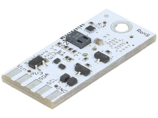
TME’s offer features miniature modules for monitoring environmental conditions from R&D SOFTWARE SOLUTIONS. The manufacturer offers the modules in several different variants differing in terms of the number and type of embedded sensors.
You can select from pressure sensors, temperature sensors, humidity sensors, CO2 sensors and VOC (Volatile Organic Compounds) sensors. The systems are powered within the range of 3.3V DC to 5V DC, which means they can be used with the most common platforms, such as Arduino, Banana Pi, Raspberry Pi, Beagle Bone, or Teensy.
The I2C communication requires the use of two microcontroller lines, regardless of the number of connected modules. This makes R&D SOFTWARE SOLUTIONS products useful even in basic systems with a limited number of pins.
Specifications
Communication standard: I2C
Available sensors, CCS811 , HDC2010 , BME280, BME680, BMP280
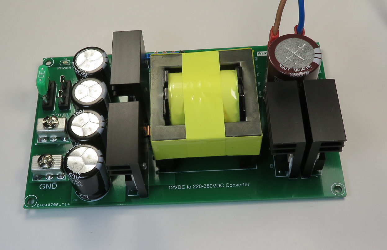
When powering many appliances from a sine wave inverter, the HV DC is converted to AC only to be rectified back to DC in the appliance.
This inverter eliminates the SPWM stage and outputs DC only. This DC can be used to power appliances, or as a HV DC source for your SPWM, variable frequency drive (.. for your inverter fridge) or other project.
Ebay, AliExpress and other like stores have cheap 12VDC to 220-380VDC Converters (pictured above), ready for purchase under board names like QS-100 and GZF-02-Y.
These basic converter boards consist of a SG3525, four IRF3205 MOSFETs and a Transformer. They include no overload protection, output regulation/feedback or DC rectification. Nor do they include low voltage cutouts.
This project intends to build upon these boards and build in these other features and protection.
The converter uses a prewound 500W Transformer available from AliExpress.
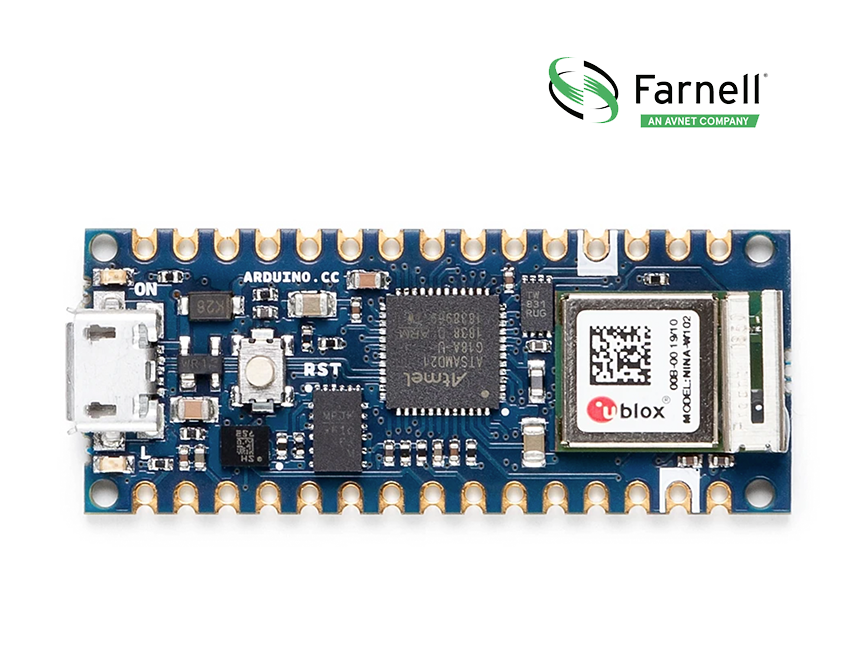
Small, robust and powerful board with Wi-Fi and Bluetooth connectivity combined with its low power architecture makes it a practical solution.
This month oemsecrets.com has teamed up with Farnell to giveaway an Arduino Nano 33 IoT development board to two lucky winners. Simply follow the link below to enter.
Get extra entries into the giveaway by following us and sharing this article on Instagram, LinkedIn, Facebook or Twitter using #oemsecrets or @oemsecrets.
The Arduino Nano 33 IoT is the easiest and cheapest point of entry to enhance existing devices (and creating new ones) to be part of the IoT and designing pico-network applications. Whether you are looking at building a sensor network connected to your office or home router, or if you want to create a BLE device sending data to a cellphone, the Nano 33 IoT is your one-stop-solution for many of the basic IoT application scenarios.
The board’s main processor is a low power Arm® Cortex®-M0 32-bit SAMD21. The WiFi and Bluetooth® connectivity is performed with a module from u-blox, the NINA-W10, a low power chipset operating in the 2.4GHz range. On top of those, secure communication is ensured through the Microchip® ECC608 crypto chip. Besides that, you can find a 6 axis IMU, what makes this board perfect for simple vibration alarm systems, pedometers, relative positioning of robots, etc.
We’re pleased to announce the 2 winners of the @arduino Nano 33 IoT in partnership with @Farnell_Avnet is “Vishnu M.” and “Muhammed Z.”. We’ll be in touch with you via email to get your shipping details. Congrats to both of you & thanks to everyone who entered. #SBC#Winnerspic.twitter.com/mPvcE7rdq8
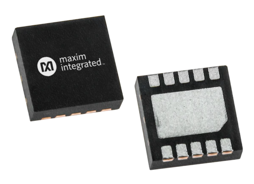
Maxim Integrated MAX25256 H-Bridge Transformer Driver provides a simple solution for making isolated power supplies up to 10W. The device drives a transformer’s primary coil with up to 300mA of current from a wide 8V to 36V direct current (DC) supply. The transformer’s secondary-to-primary winding ratio defines the output voltage, allowing the selection of virtually any isolated output voltage.
The device features adjustable current limiting, allowing indirect limiting of secondary-side load currents. An external resistor sets the current limit of the MAX25256. An output asserts when the device detects an overtemperature or overcurrent condition. In addition, the device features a low-power mode to reduce the overall supply current to 0.65mA (typ) when the driver is not in use.
The device can be operated using the internal oscillator or driven by an external clock to synchronize multiple Maxim MAX25256 devices and precisely set the switching frequency. Internal circuitry guarantees a fixed 50% duty cycle to prevent DC flow through the transformer, regardless of which clock source is used.
The device is available in a small 10-pin (3mm x 3mm) TDFN package and is specified over the -40°C to +125°C automotive temperature range.
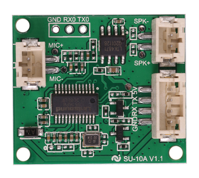
Nowadays, almost all applications and devices provide speech recognition functionality, this makes the device look smart and user-friendly. Cloud plays an important role in integrating such features in hardware systems. But it increases the cost due to additional wireless components and complexity in the architecture of the device. Hence, an offline speech recognition feature can be the solution to reduce the cost significantly, thus making the system much more affordable for potential customers.
SU-10A module is one such solution for integrating offline speech recognition functionality. It has a very simple architecture with speakers connections for output audio and microphone connections for input audio. It also comes with a UART interface for the communication of audio signals with the host processor. One of the UART ports functions as a serial console and the other one is for connecting the module with an external device.
The module comes with the 32bit RISC core featuring the Unisound US516P6 microcontroller. It operates at a high frequency of 240MHz, thus supporting the extensive computation for speech recognition on the module itself. Discussing further, it contains 242kB of SRAM and 2MB of flash memory, which seems to be enough for accommodating the speech data. Additionally, it comes with a floating-point unit and accelerators for digital signal processing (DSP) and fast Fourier transform (FFT) computations.
Features of SU-10A Speech Recognition Module
Unisound US516P6 RISC microcontroller operating at 240 MHz.
It features FPU, DSP instruction, FFT accelerator, 242KB SRAM, and 2MB flash.
Built-in 3W mono Class AB power amplifier.
UART port for the serial console to program the module.
2mm pitch 4-pin connector for UART (Tx/Rx) to host MCU.
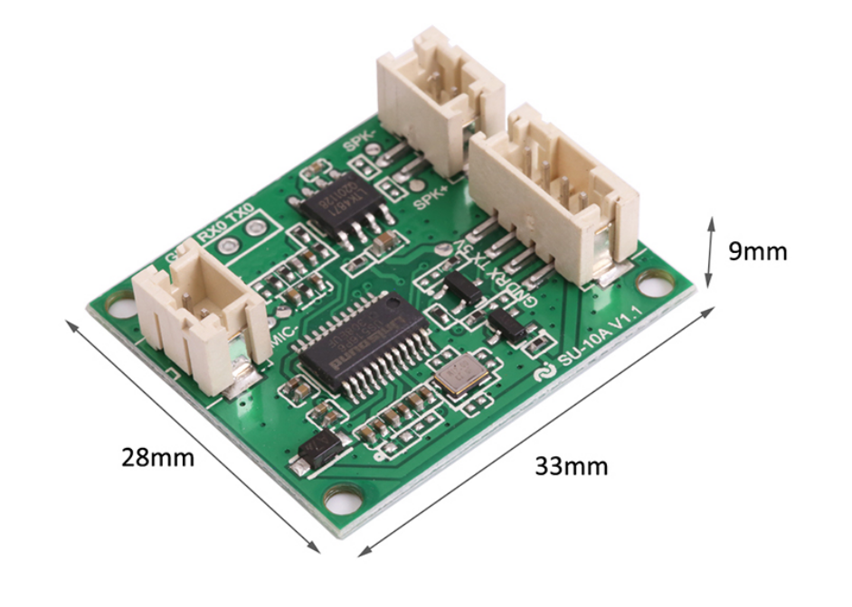
The dimensions of the module are 33mm x 28mm x 9 mm
One of the major utilities of the module is its solderless pins for connecting speakers, thus making it perfect for DIY integration with the existing applications as well. Talking more about the speakers, it provides an output power of 2.9 W for 4 ohms load, and 1.8W for 8 ohms load. The average power consumption of the SU-10A speech recognition module is 60mA with a supply voltage of 5 V.
The working temperature range for the SU-10A speech recognition module is from 20°C – 85°C. The module is available at $4.24 USD in IC Station store.
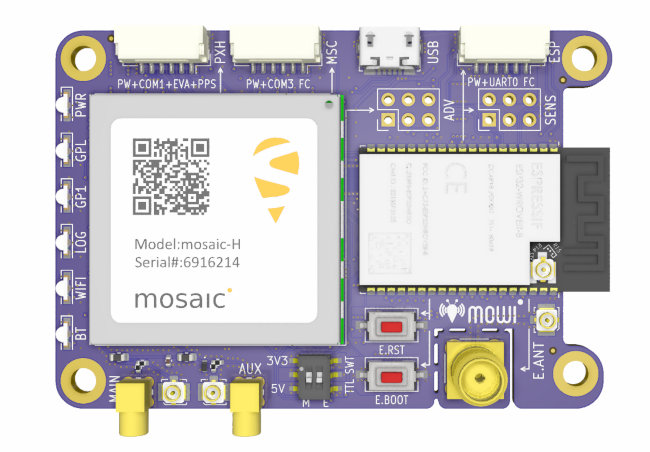
Septentrio announces an important addition to the open-source resources for their GPS/GNSS module receivers: mosaicTM wireless or simply mowi. It combines the Septentrio mosaic-X5 or mosaic-H module receiver with a dual-mode Bluetooth and integrated Wi-Fi from the well-known ESP32- WRover programmable module by Espressif Systems. It is an addition to the already existing mosaicHAT board, designed on the Raspberry Pi platform.
The mowi project facilitates accurate and reliable GNSS positioning for robotic and autonomous devices, on a hardware level. Numerous engineers today use the ESP32 and the multiple libraries available for Internet-of-Things (IoT) prototyping. The mowi board is an easy way for integrators to get started with Septentrio’s mosaic-X5 or mosaic-H heading module receivers. The mowi board can be used on its own or plugged into a mobile computer such as Raspberry Pi or Arduino to deliver high-accuracy positioning with high update rates, ideal for machine navigation, monitoring, or control. The internet connection via Wi-Fi or Bluetooth enables numerous industrial IoT applications, simplifying the connectivity to mobile data for the delivery of GNSS corrections needed for cm-level RTK positioning.
On top of the wireless communication, the small 47.5×70 mm board can host IoT applications in its internal memory. It has onboard logging and exposes interfaces such as USB, serial communication, and general-purpose pins. The schematic’s reference design, PCB layout, and documentation are openly available for prototyping or further customization.
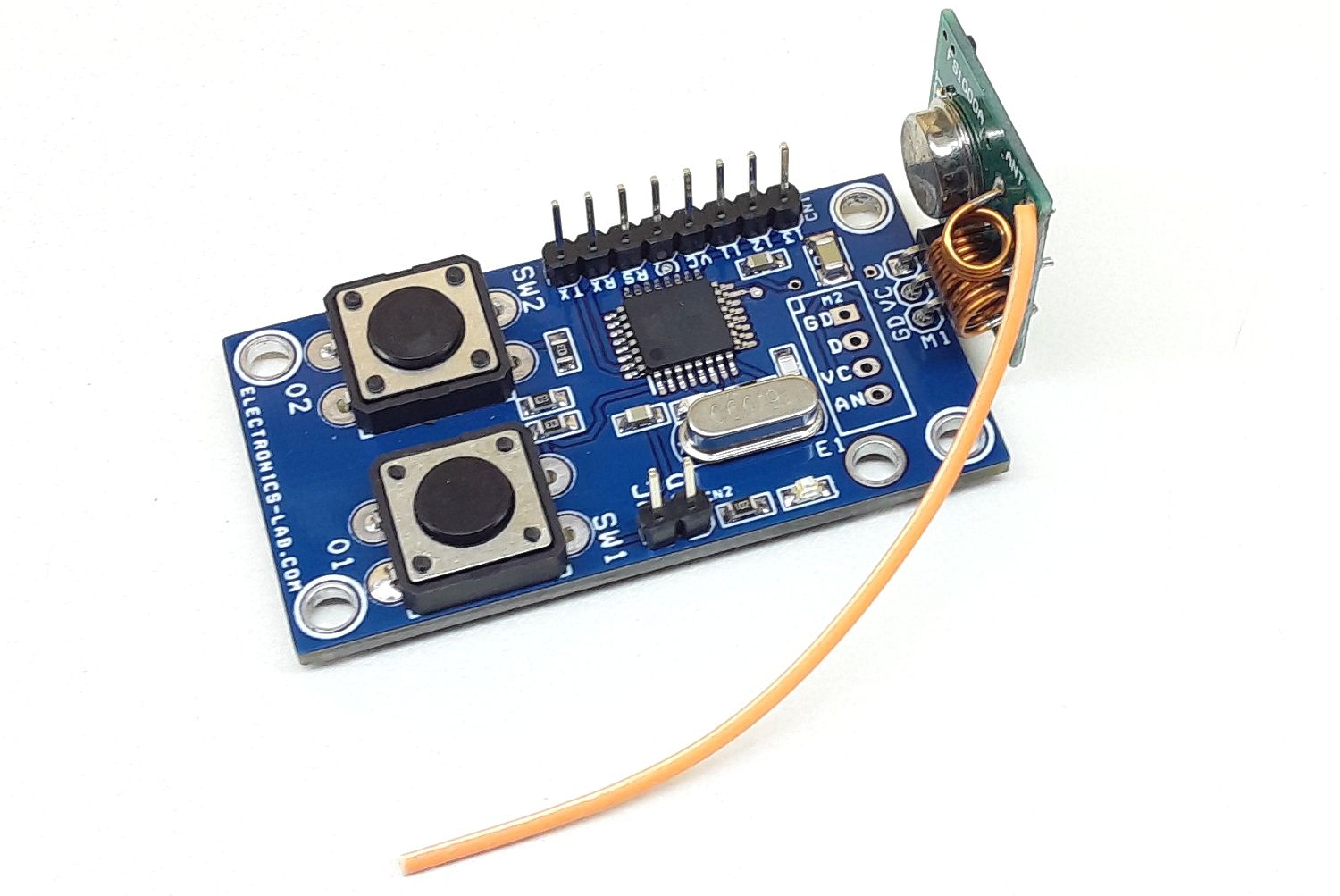
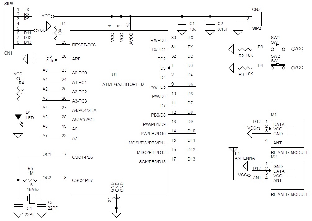
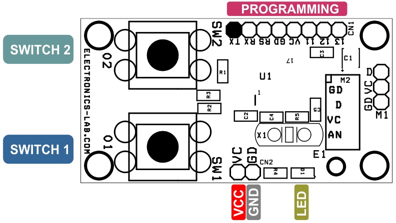
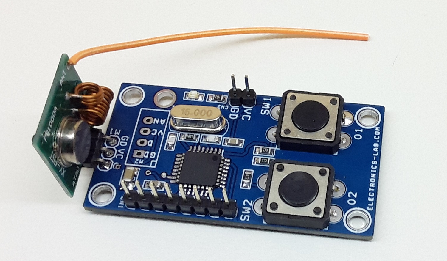
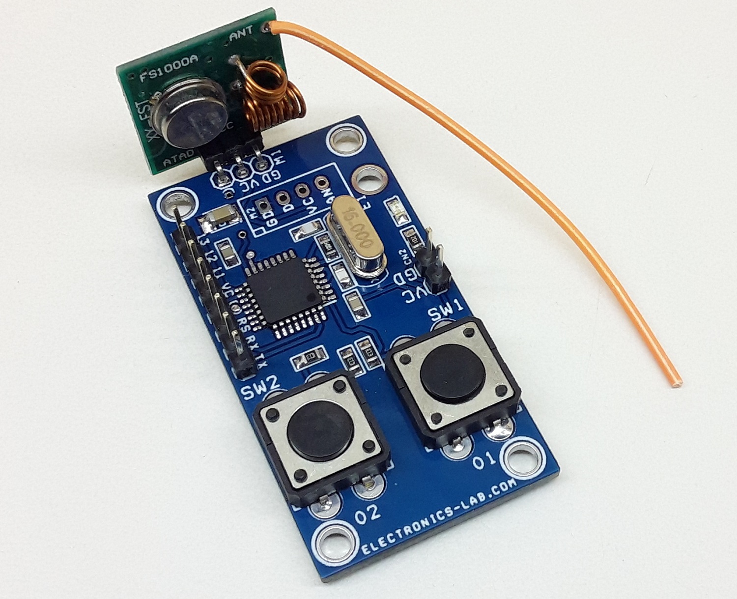
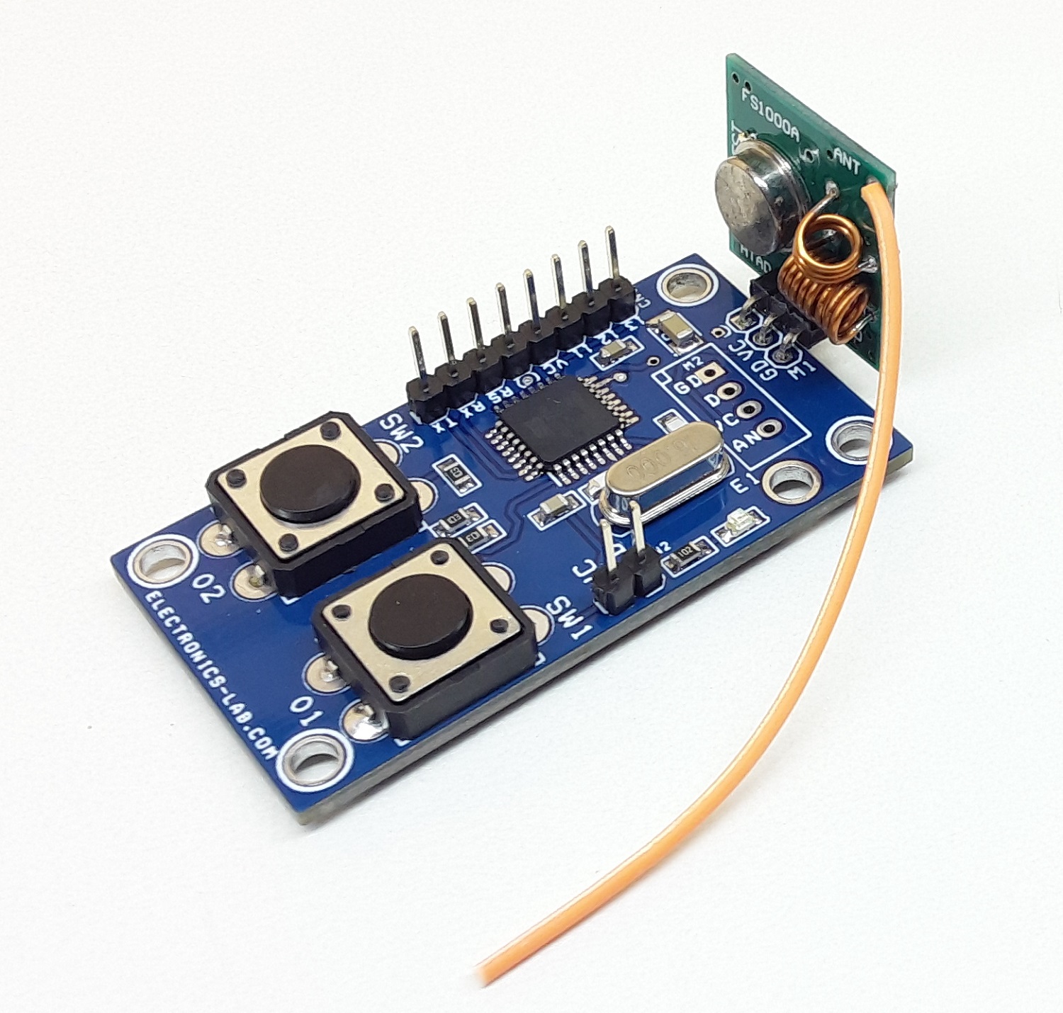
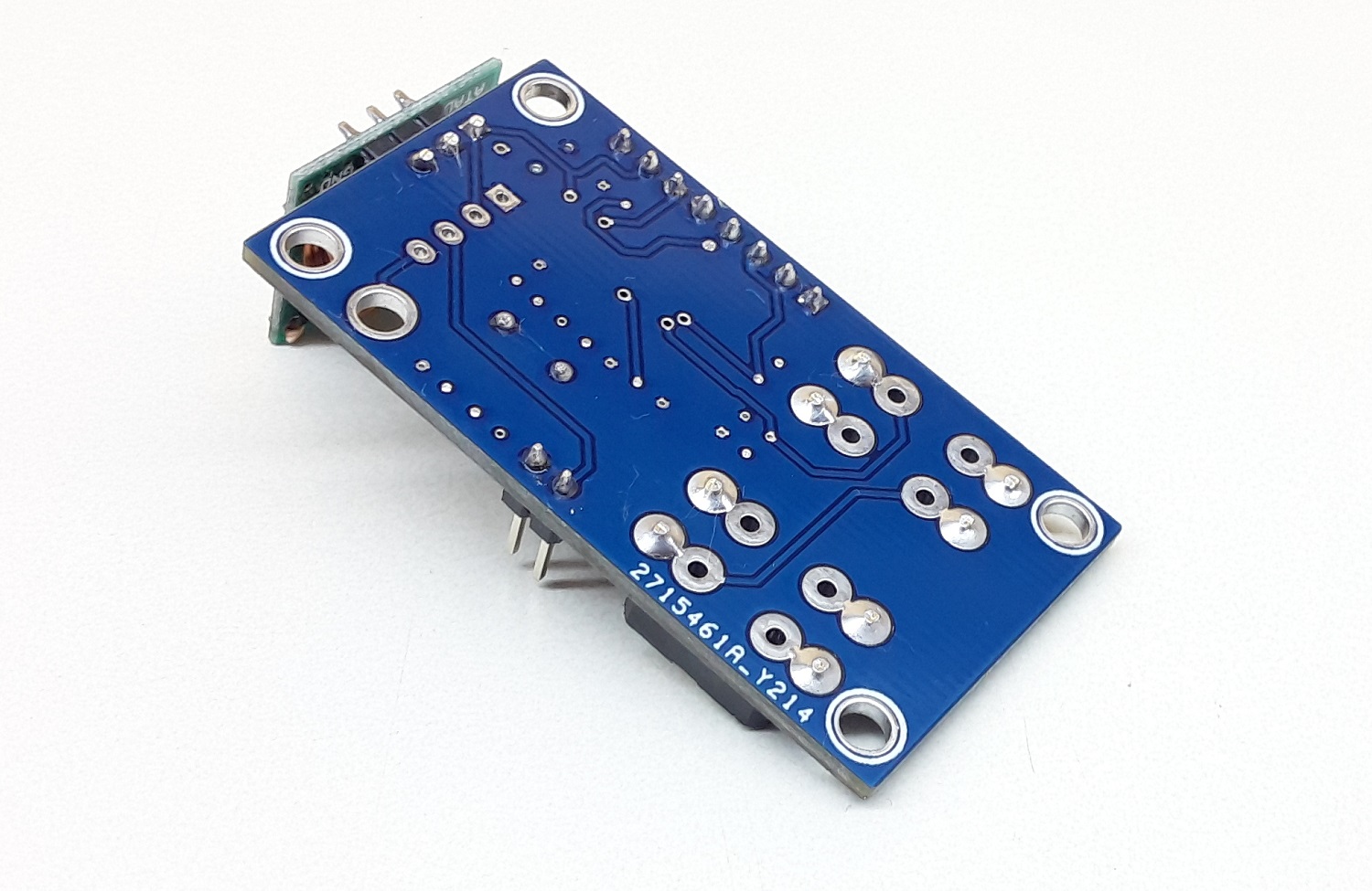
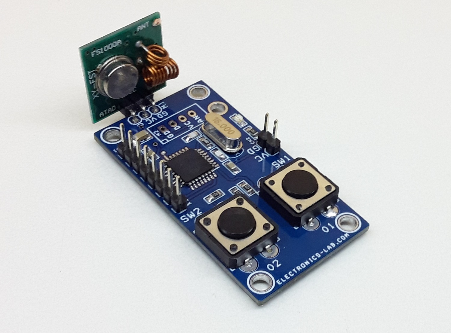
This is a two-channel RF Transmitter unit that consists of, Atmega328 microcontroller, 2 Tactile switches with pull-down resistors, a programming port, and a 315Mhz RF transmitter module. It is an Arduino compatible open-source project that can be used for many RF transmitter applications. It is advisable to use 1 Foot hook-up wire as Antenna to enjoy a maximum range of the transmitter.
Arduino Pins: D3, D4 Tactile Switch and D12 data out for AM transmitter
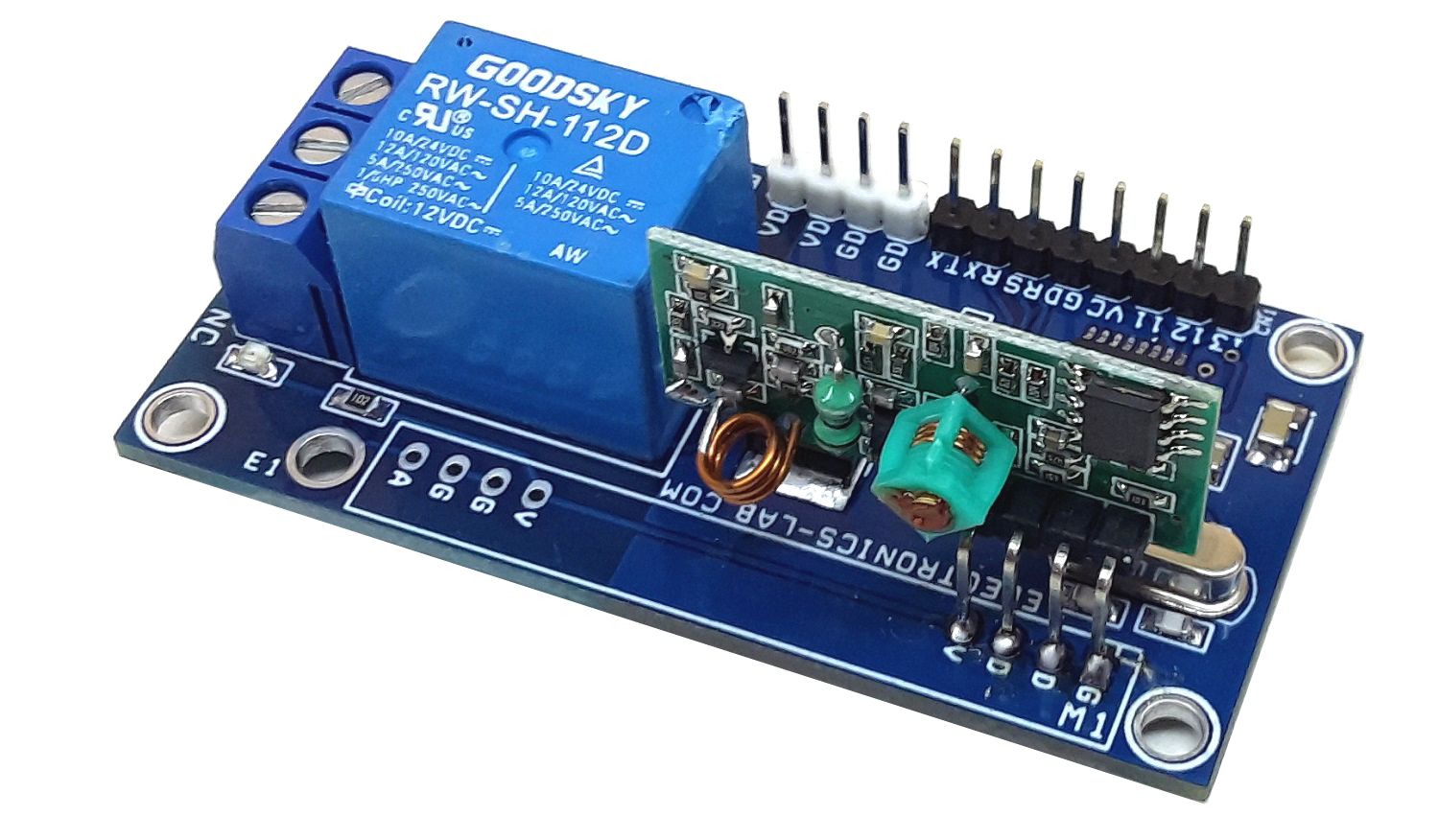
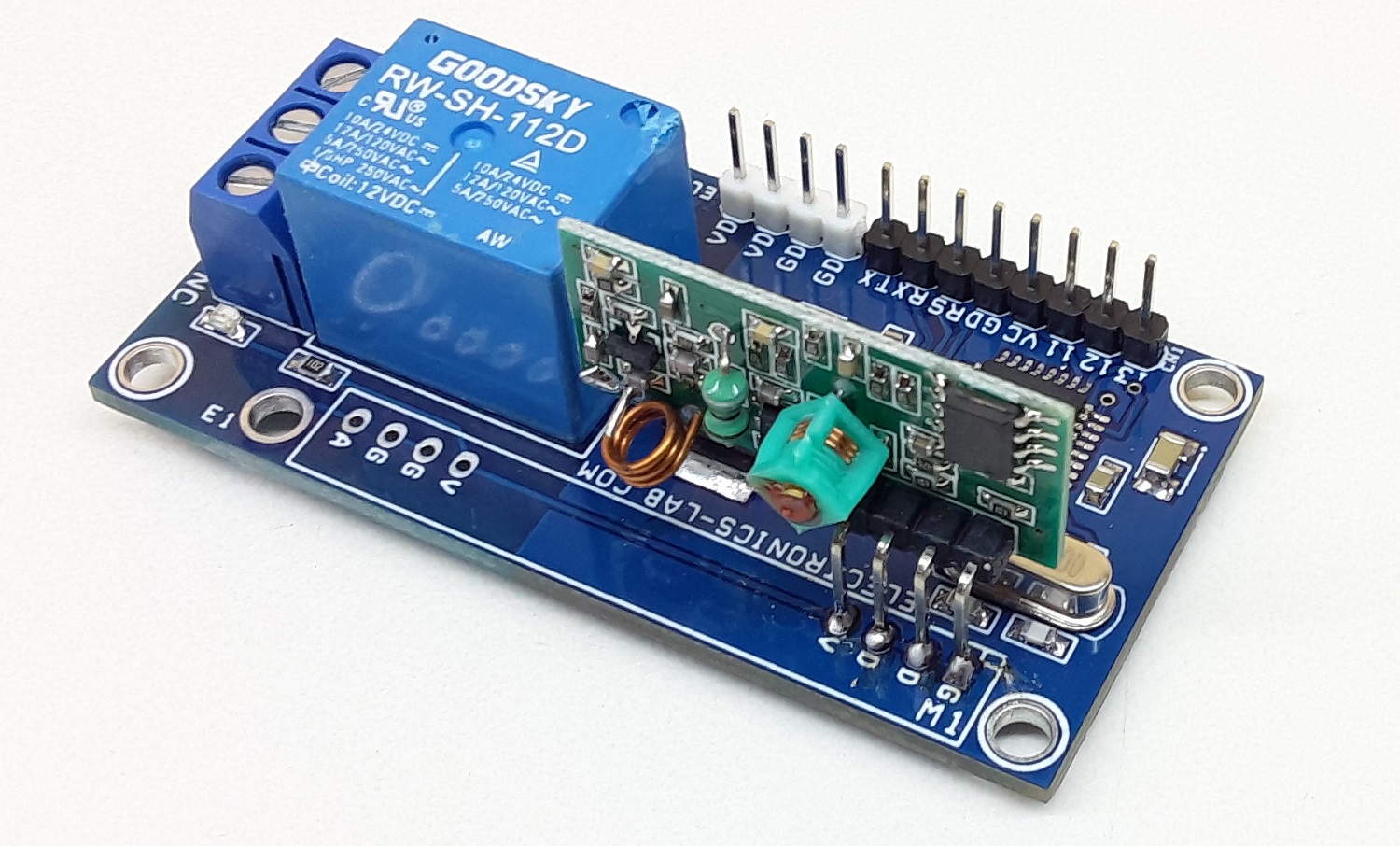
Note1: The PCB is compatible with 2 types of RF modules, 3-Pins or 4-Pins. Use a suitable connector as per module.
Note2: This project is compatible with our 1 channel RF relay board. The Arduino code is available as a download for the transmitter.
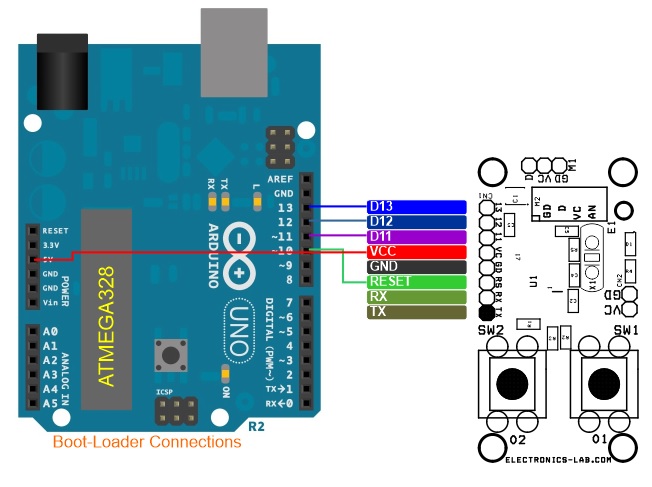
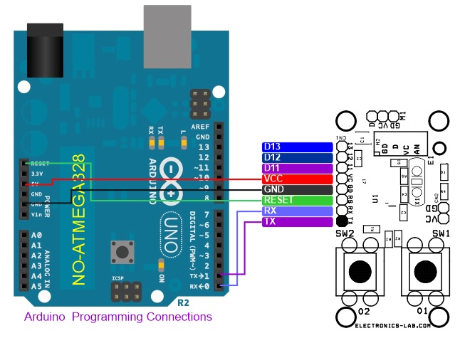
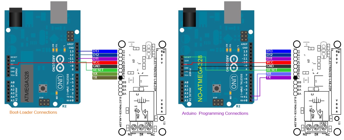
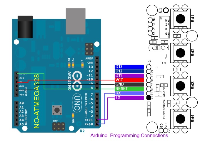
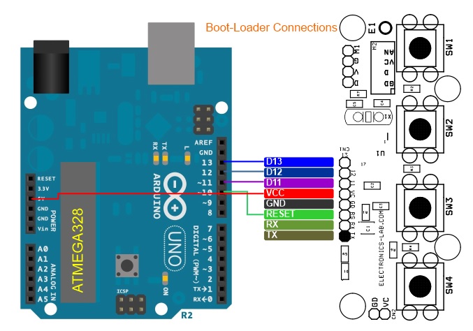
Arduino Code is provided as a download The code works with single SW1, it toggles the Receiver Relay when the switch is pressed. A new Atmega328 chip requires Bootloader and Arduino firmware programming. Please, check the link below to learn more about programming the new Atmega328. Transmitter PCB has an onboard programming port.
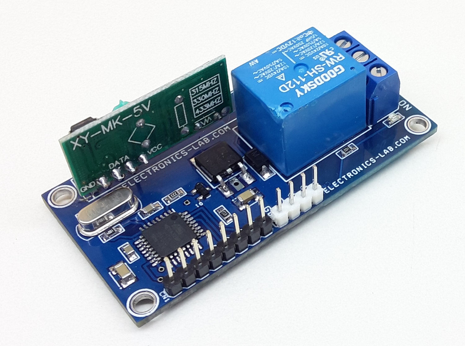
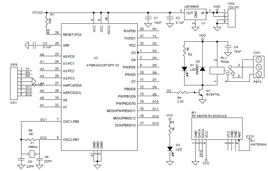
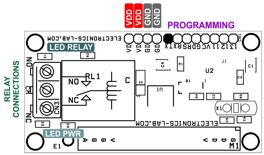
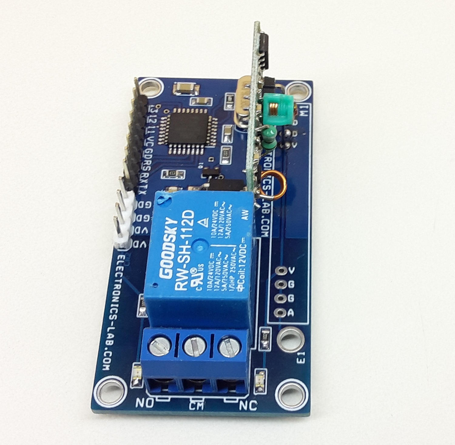
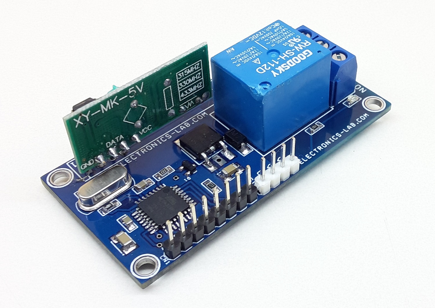
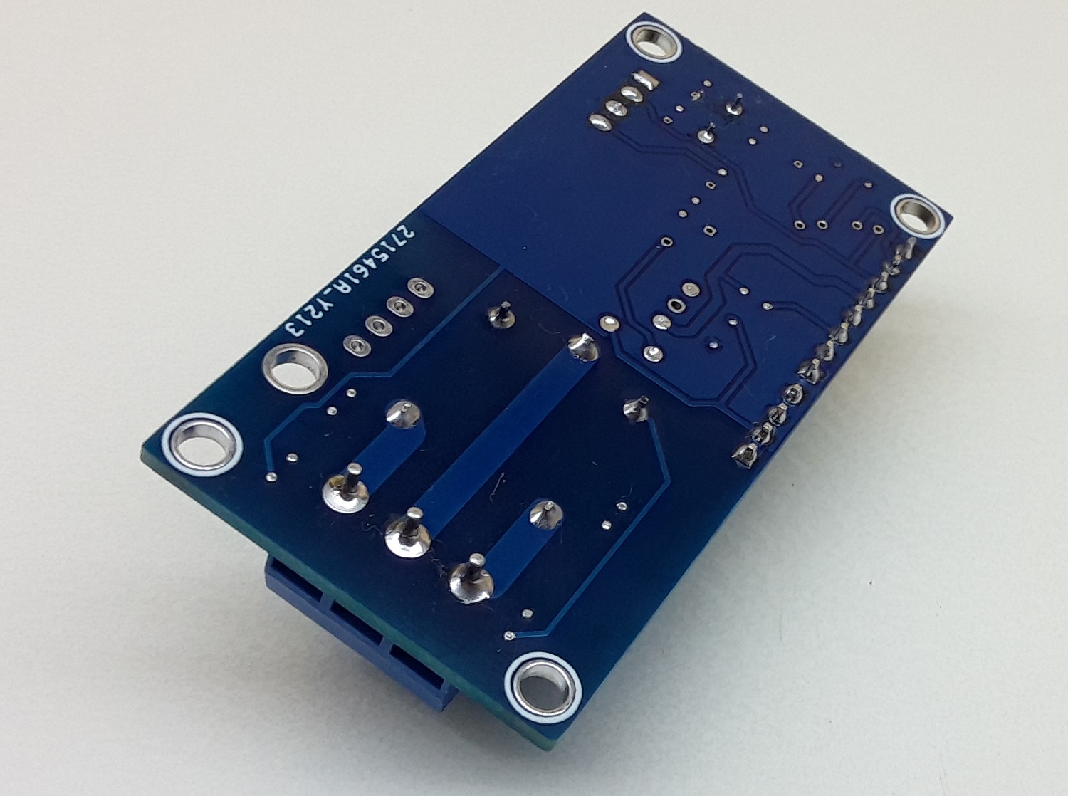
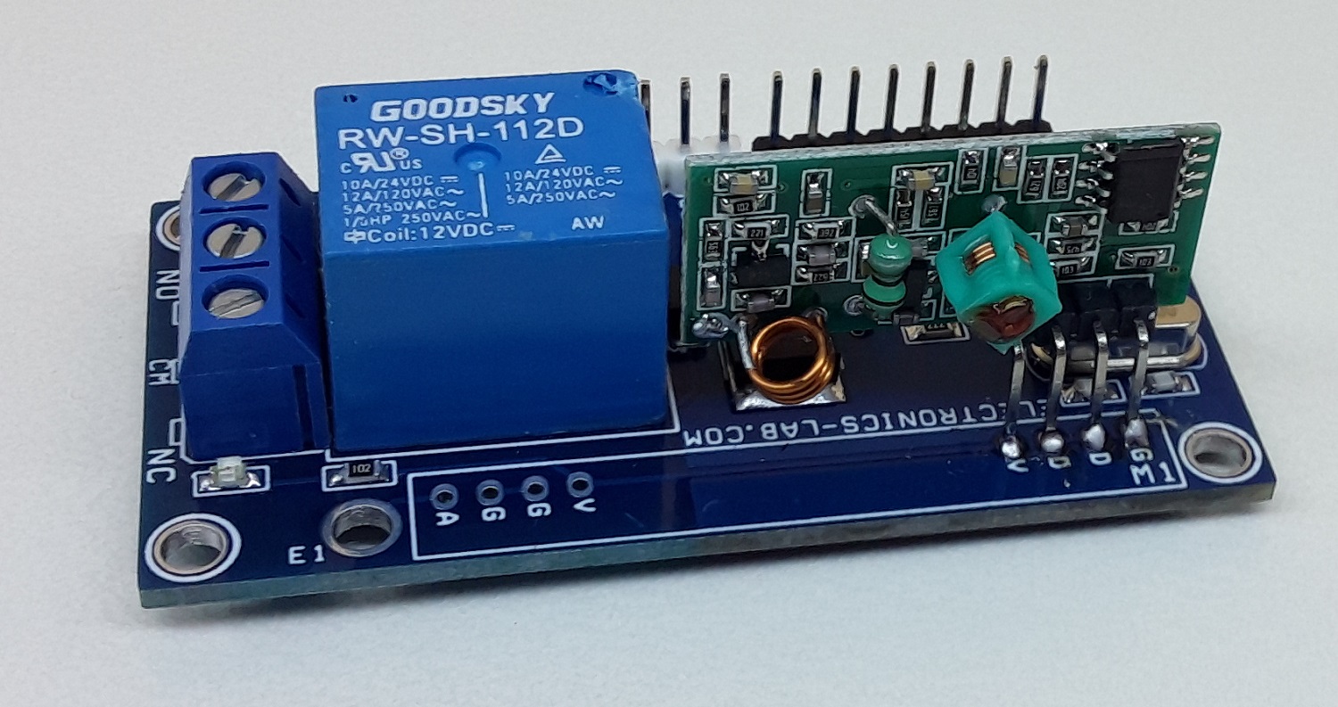
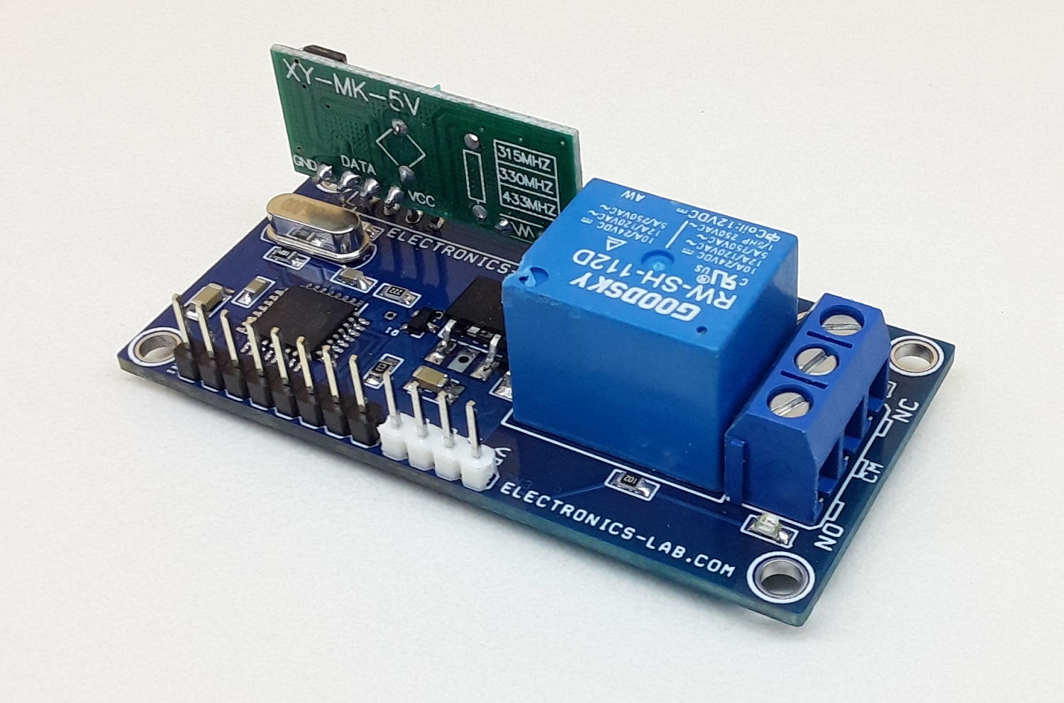
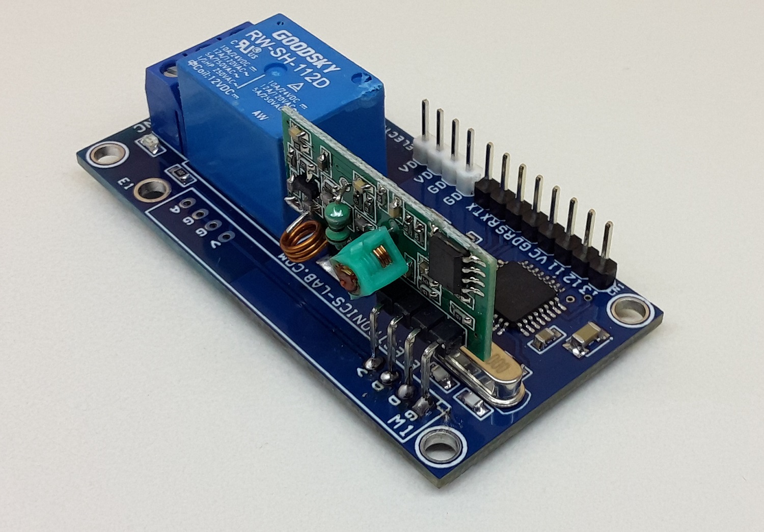
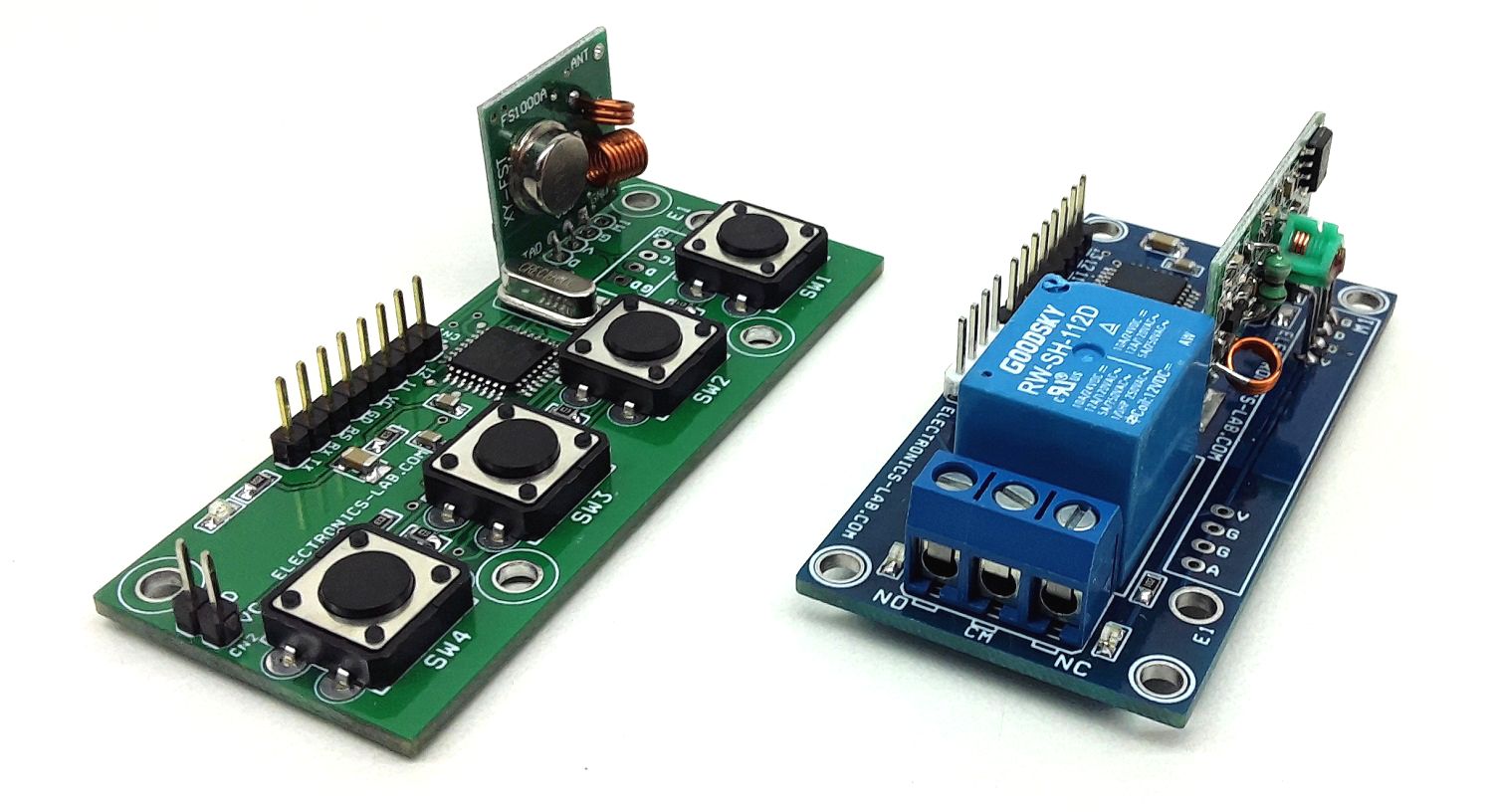
This is one channel RF Receiver with an onboard Relay. The project can be used for ON/OFF control of AC or DC loads using an RF remote. It’s an Arduino compatible Receiver project that consists of, Atmega328 microcontroller, 315MHz RF Receiver, 12v Relay, 5V Regulator, etc.
Arduino Pins Receiver: D3 Relay, D11 Data in from AM 315Mhz Receiver.
Arduino Code provided as a download. The code is compatible with our 315Mhz Transmitter project, it toggles the Relay when the switch is pressed. A new Atmega328 chip requires Bootloader and Arduino firmware programming, check link bellow to learn more about programming the new Atmega328. PCB has an onboard programming port.
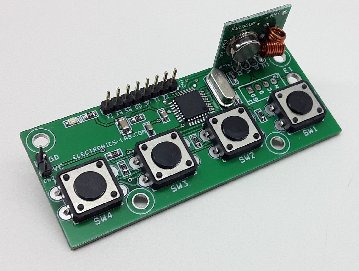
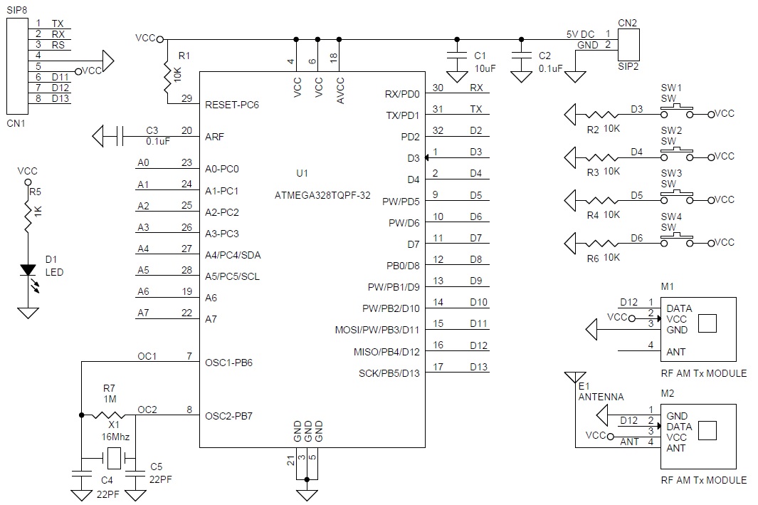
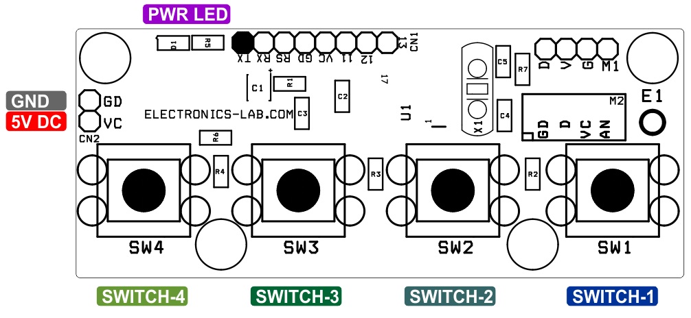
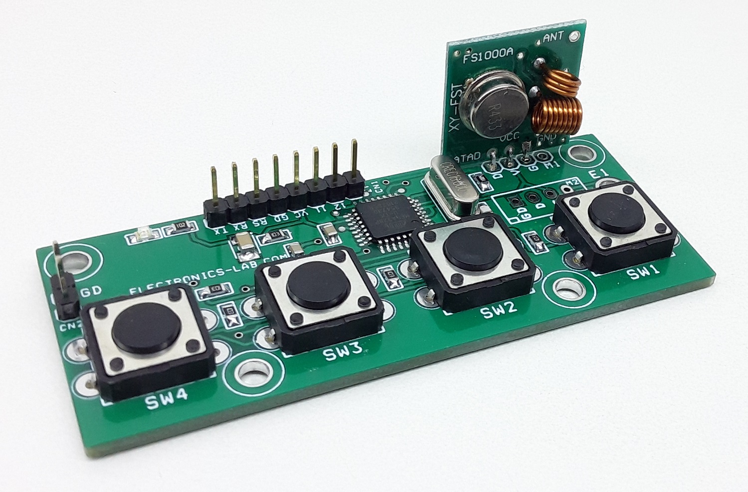
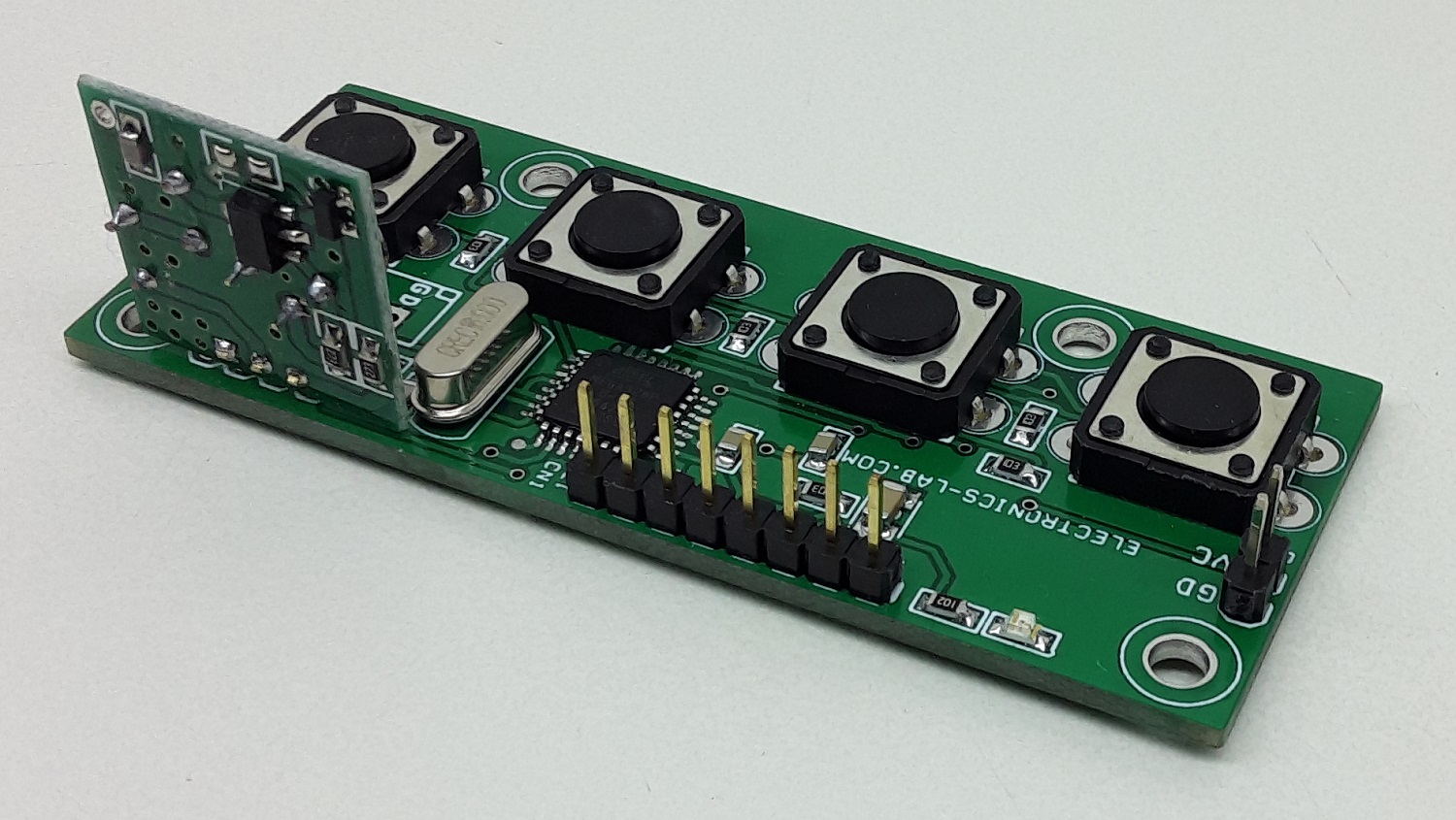
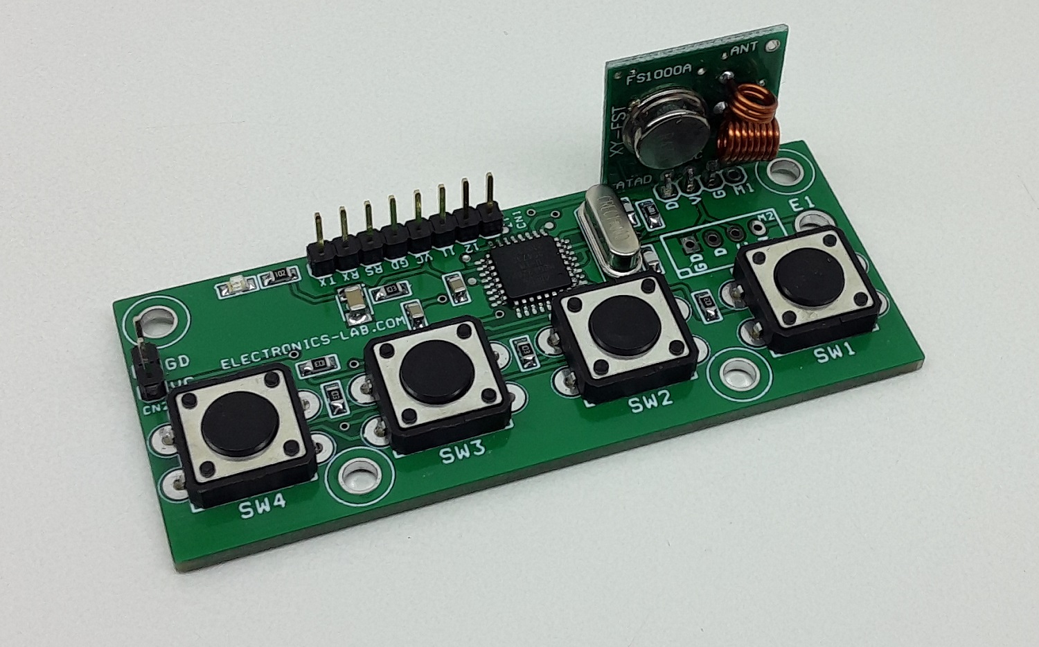
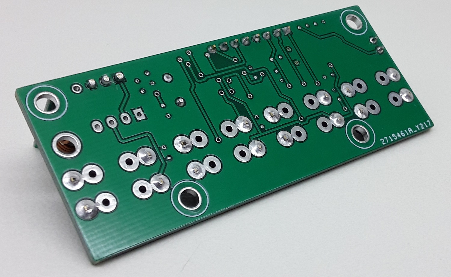
This is a 4 channel RF Transmitter unit that consists of an Atmega328 microcontroller, 4 x tactile switches with pull-down resistors, programming port, and 315Mhz RF transmitter module. It is Arduino compatible open-source project that can be used for many RF transmitter applications. It is advisable to use a 30cm hook-up wire as an antenna to enjoy a maximum range of the transmitter.
Arduino Pins: D3, D4, D5, D6 Tactile Switch, and D12 data out for AM transmitter module.
Note1: The board will work with 2 types of RF modules, 3-Pins or 4-Pins ones. Use a suitable connector as per module.
Note2: This project is compatible with our 1 channel RF relay board. Users may use up to 4 different receivers. Arduino code is available as a download for transmitter and receiver
Arduino Code is available as a download. The code works with a single SW1, it toggles the Receiver Relay when the switch is pressed. A new Atmega328 chip requires a Bootloader and Arduino firmware, check the link below to learn more about programming the new Atmega328.
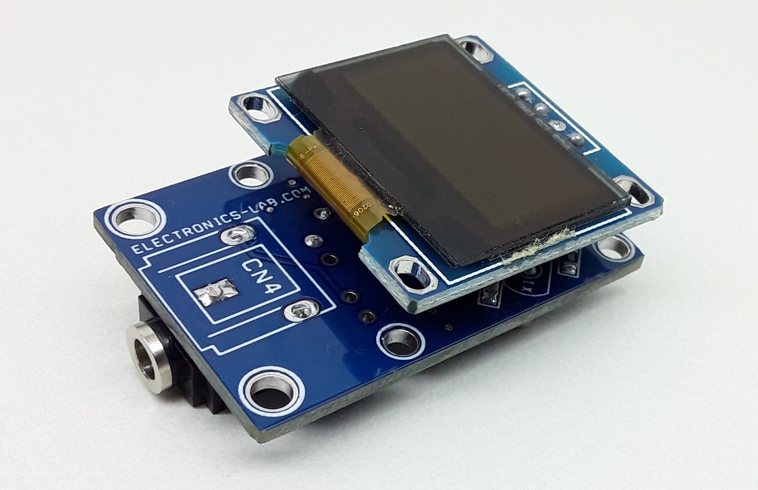
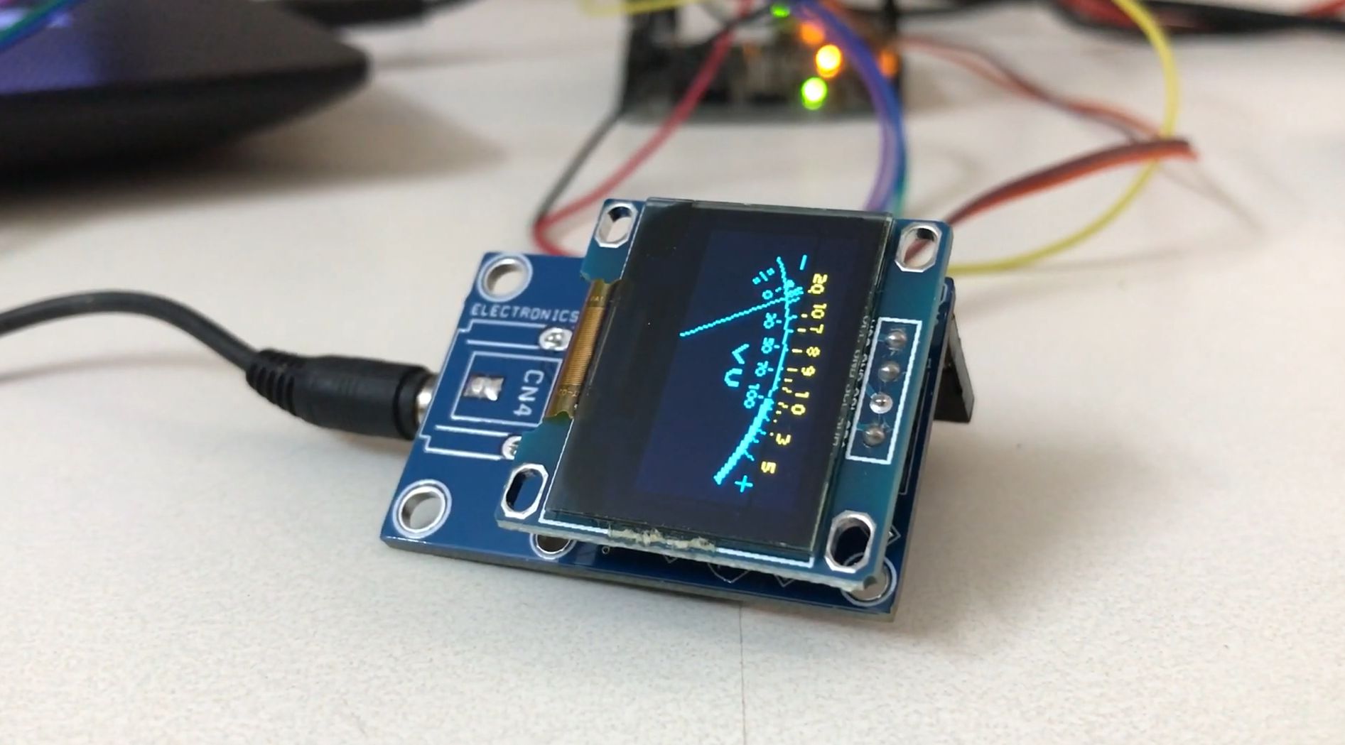
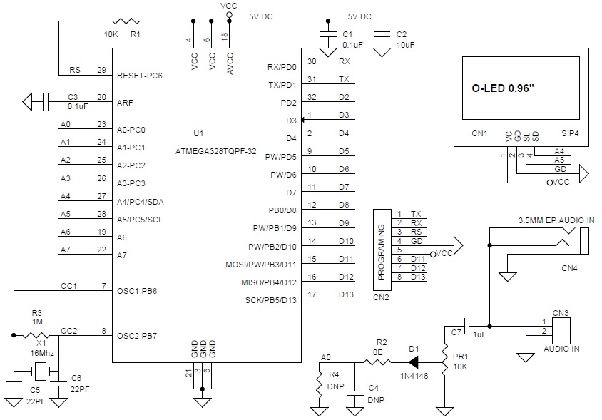
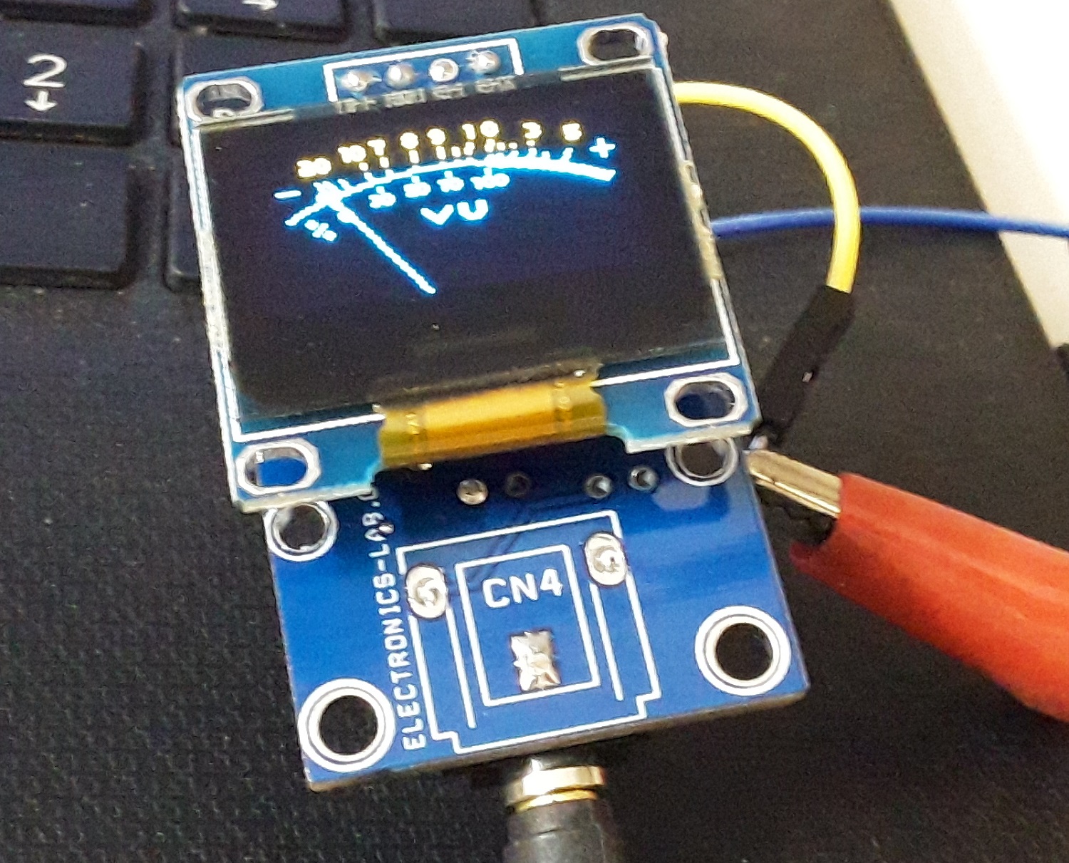
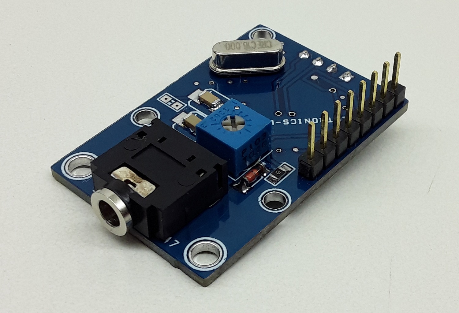
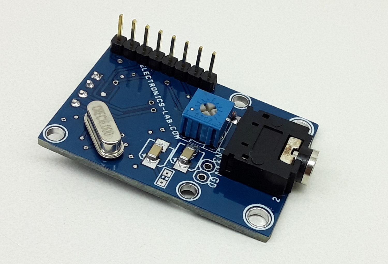
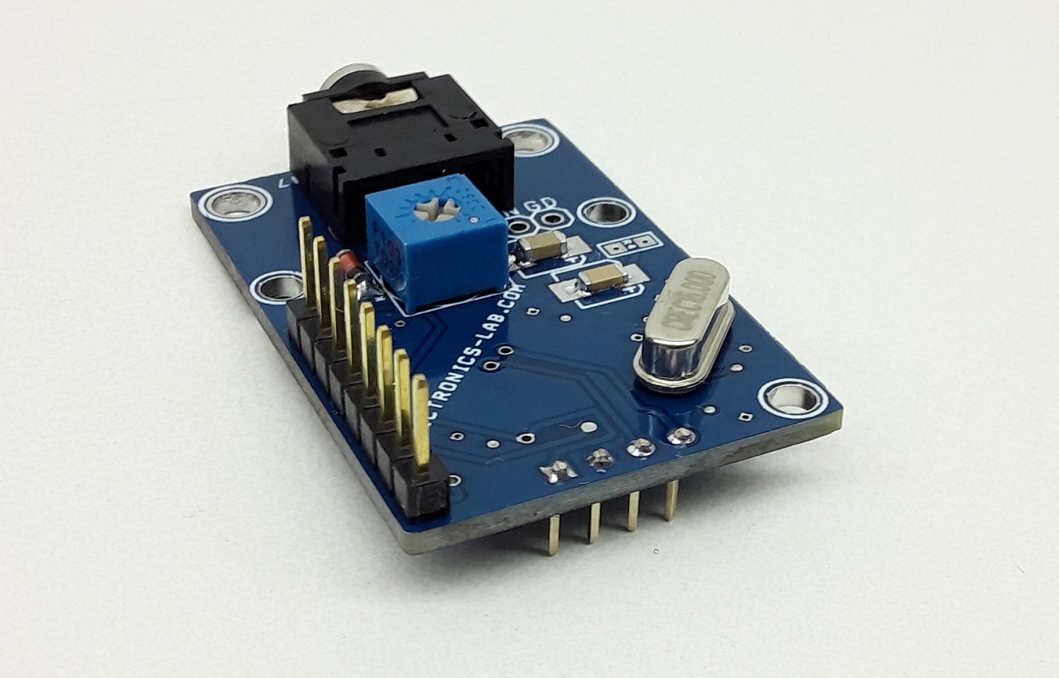
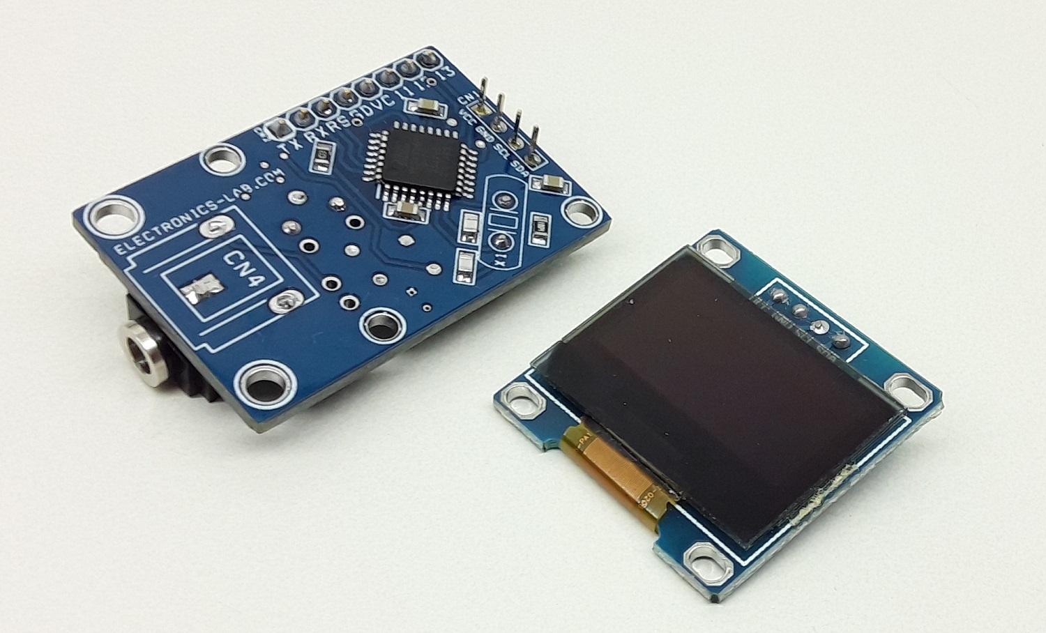
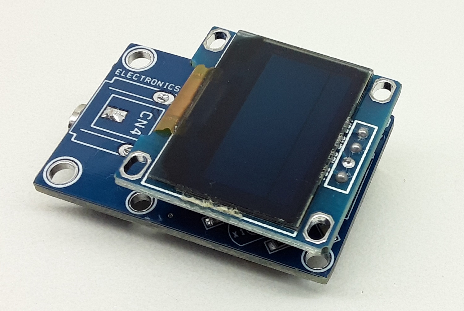
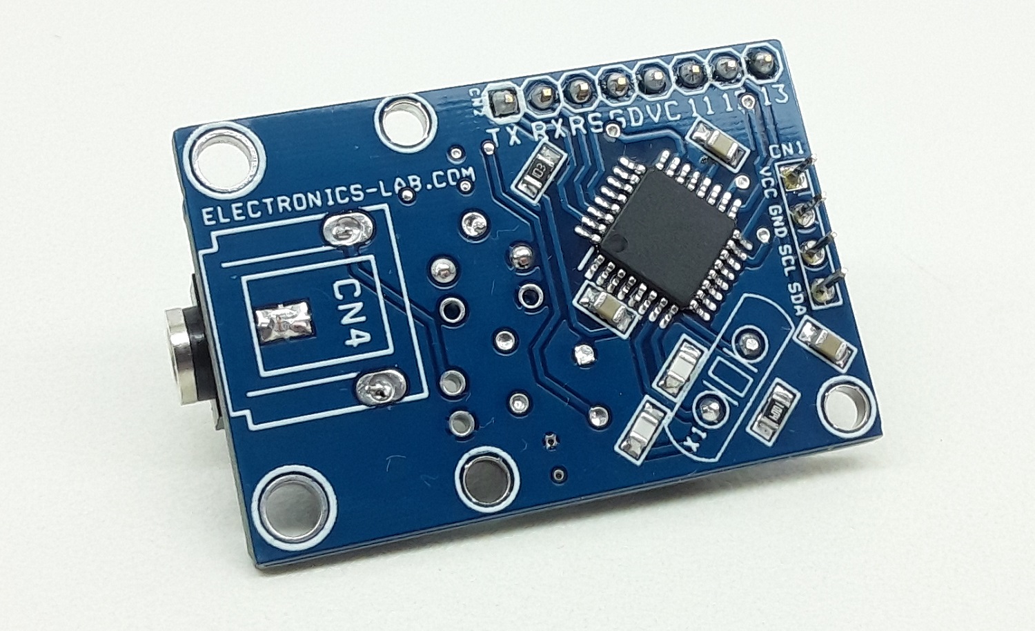
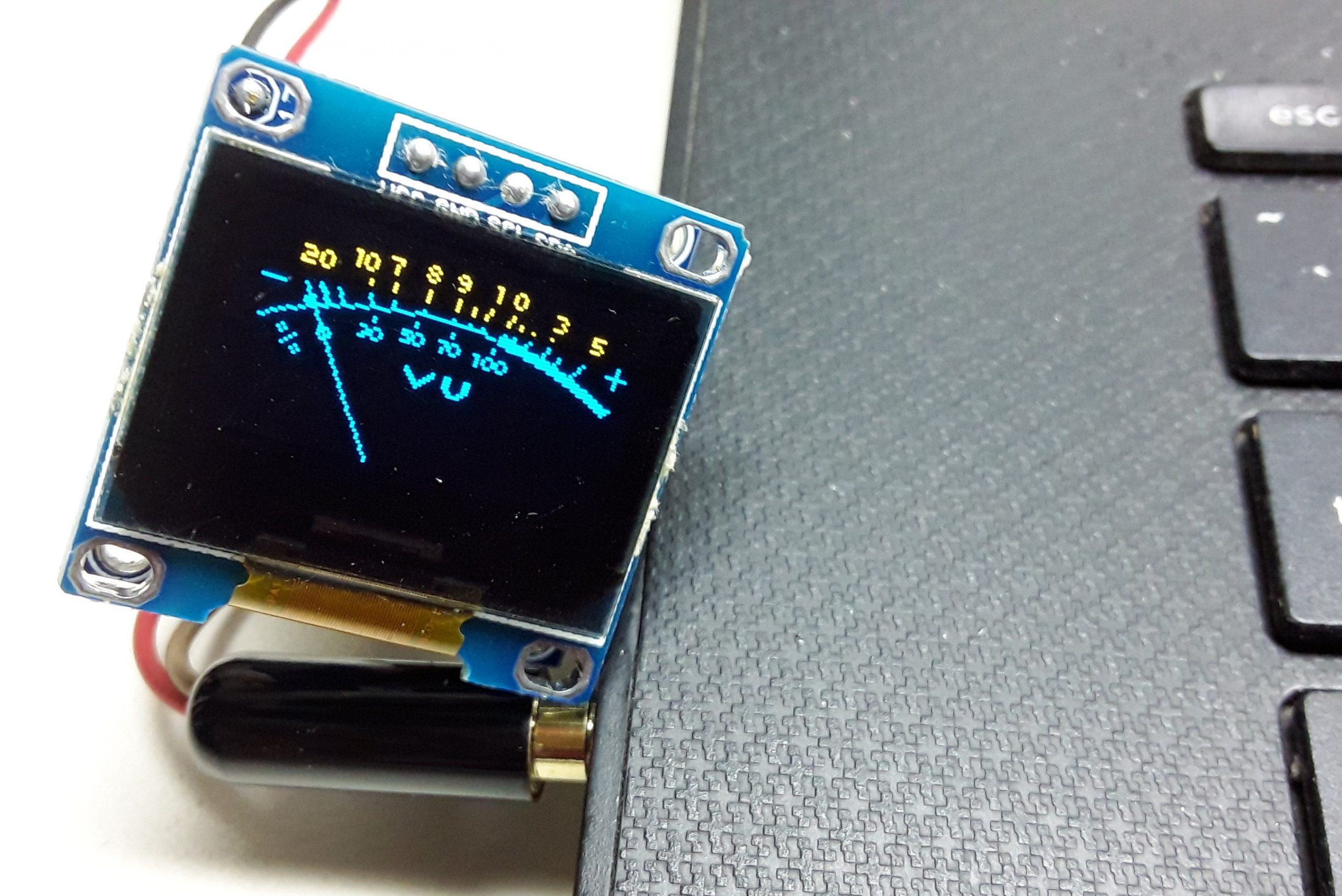
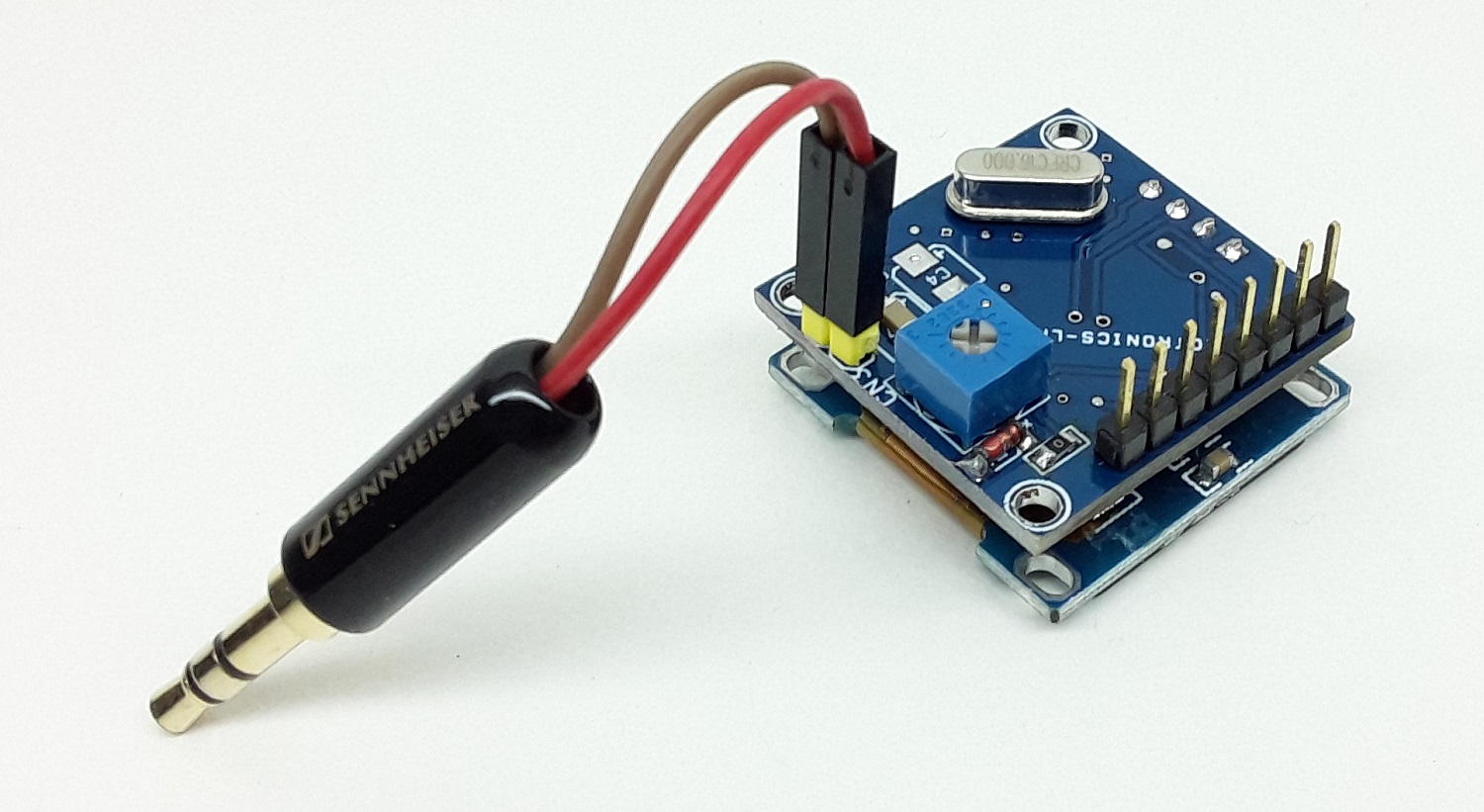
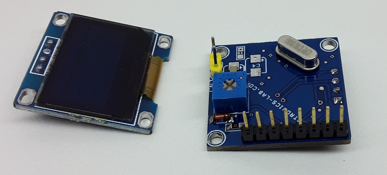
This is an analog-style VU meter on a 0.96″ OLED Display. The project has a 0.96″ OLED display, Atmega328 Microcontroller, 3.5 mm audio EP socket for audio signal input. This Arduino compatible hardware can be program using Arduino IDE. Operating Supply 5V DC.
Specifications
Operating Supply: 5V DC
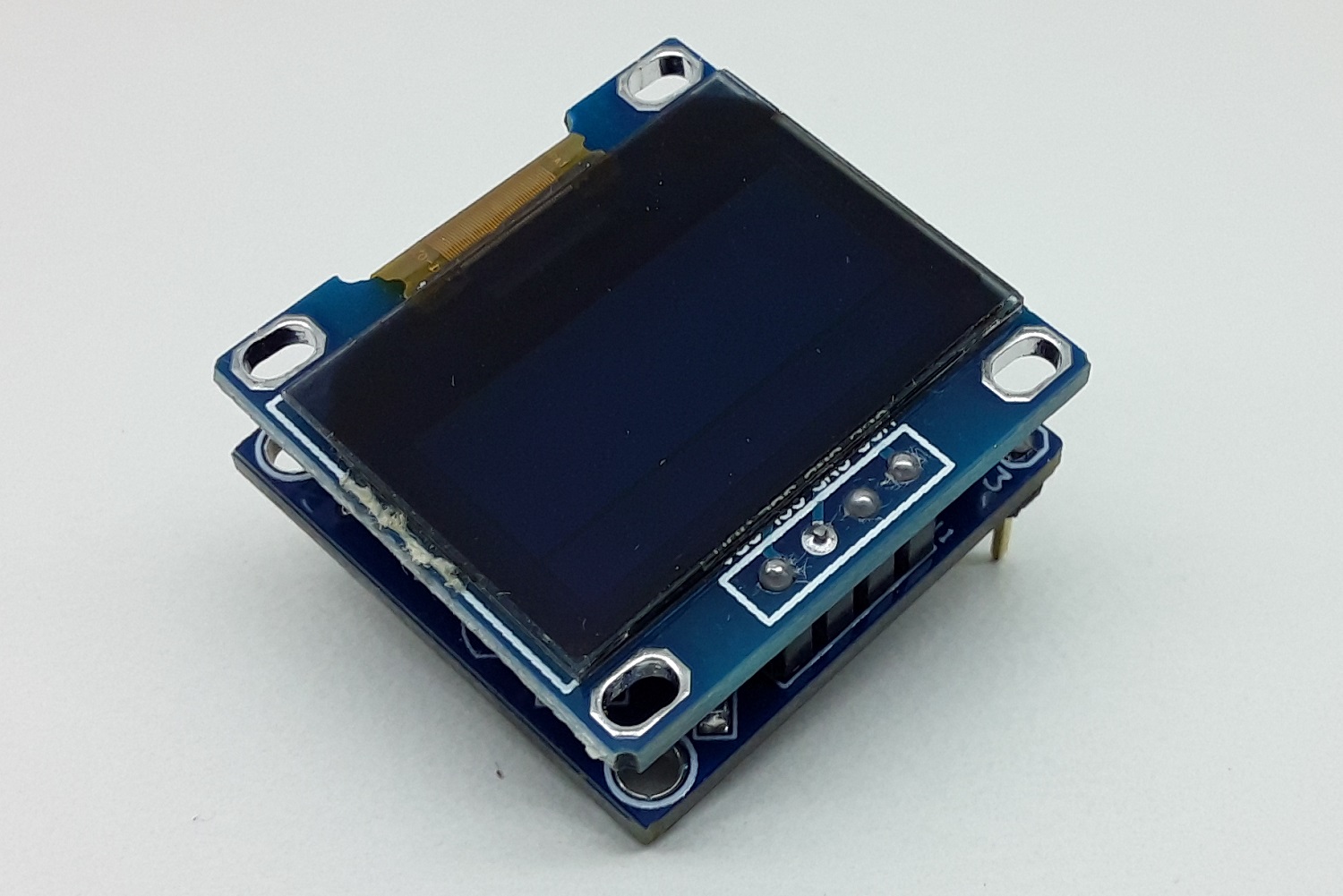
0.96″ OLED display
Arduino Compatible
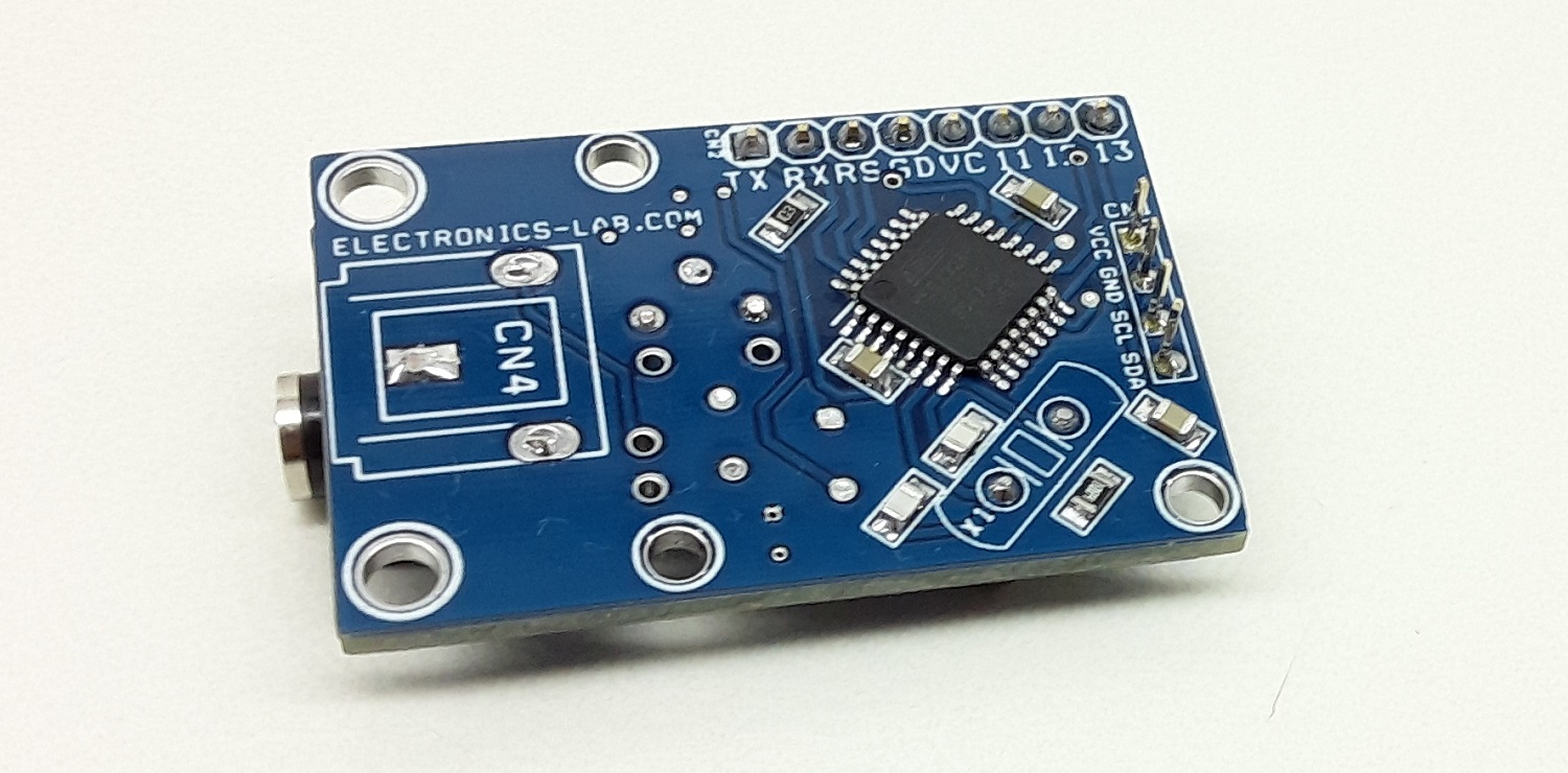
PCB dimensions: 40.48 x 27.31 mm
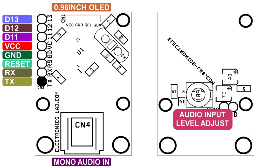
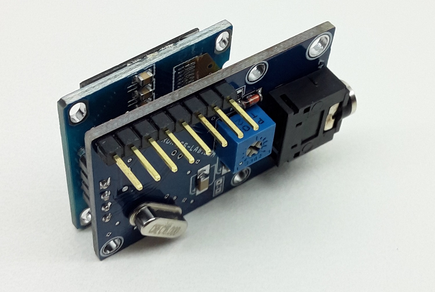
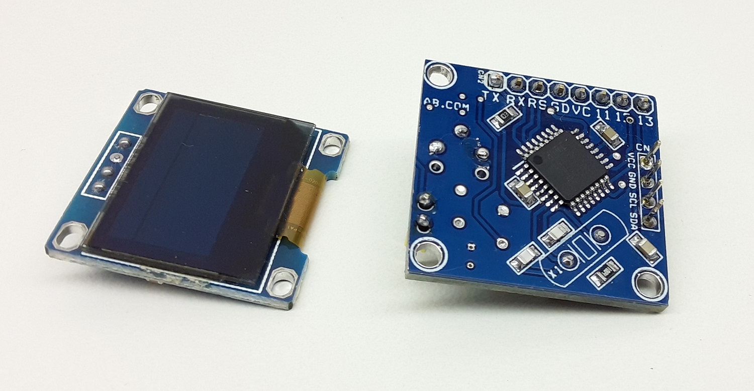
Connections
CN4 or CN3: Audio Signal Input (From Headphone or Audio Signal)
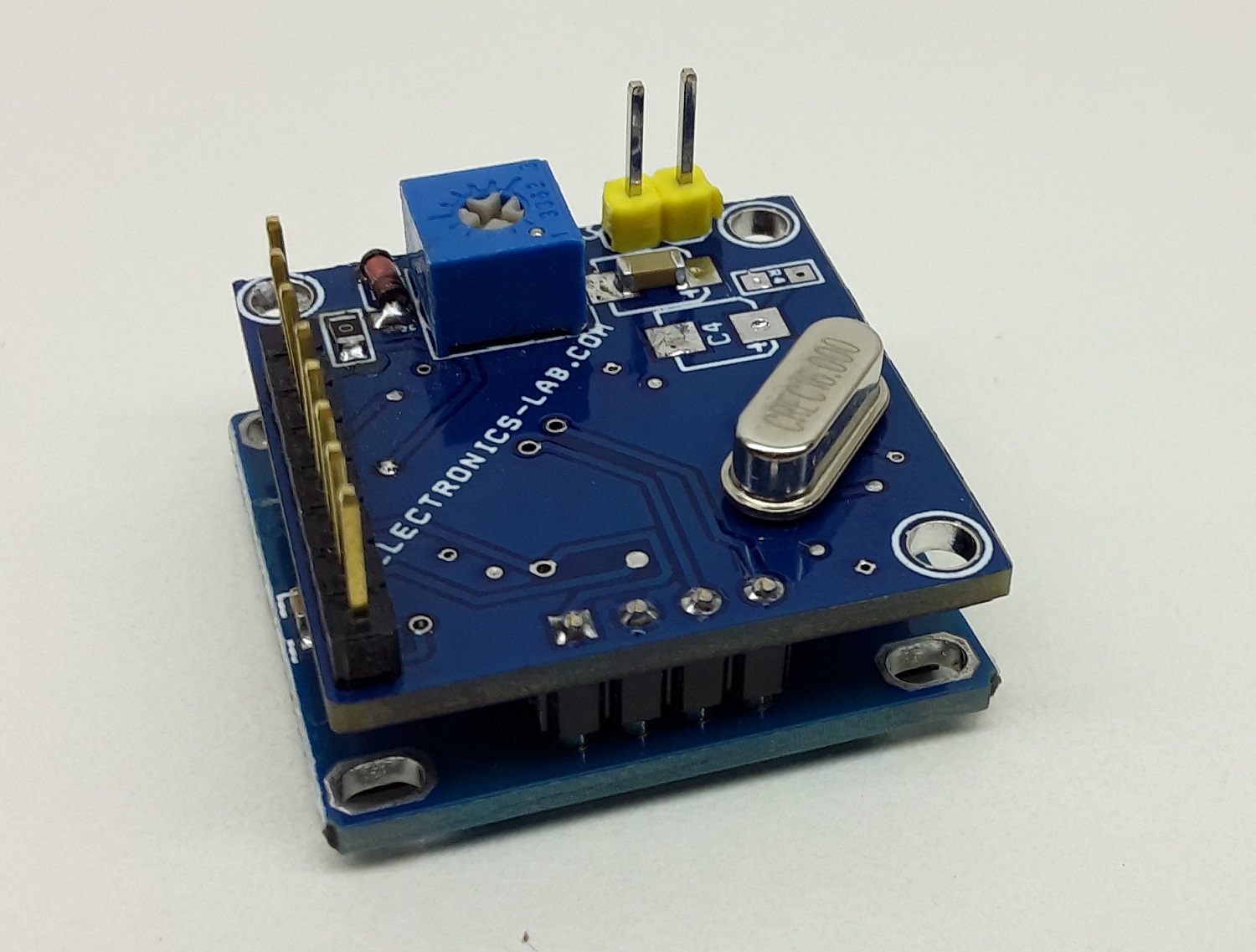
PR1 Trimmer Potentiometer: Audio Signal Level Adjust
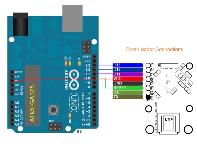
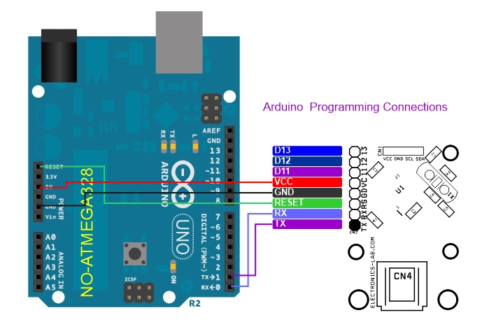
Arduino code is available as a download to test the project. A new ATMEGA328 chip is required to bootloader flashing before programming the microcontroller with Arduino IDE. For more info check the link below:
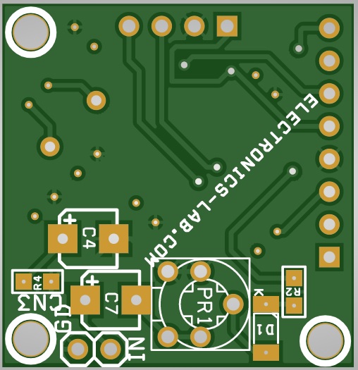
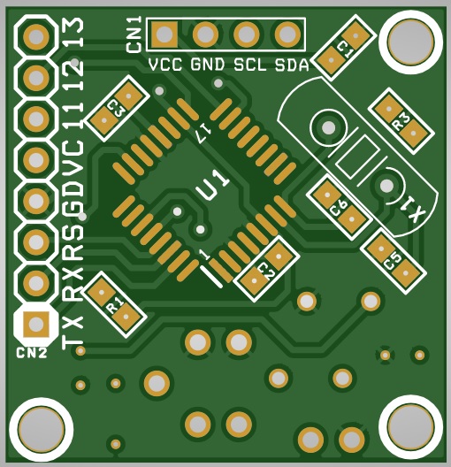
This is Version 2.0 of the above VU meter which the PCB is smaller and audio input is connected to a header connector and not a 3.5 mm female jack. To build this project use Gerbers_V2.0.zip