Sensirion SEK-SFM3119 Flow Meter Evaluation Kit

Sensirion SEK-SFM3119 Flow Meter Evaluation Kit is designed to quickly and easily evaluate the SFM3119 Low Pressure Drop Digital Flow Meter. The kit includes a flow sensor, connector cable, and downloadable SEK-ControlCenter software. The kit requires a SEK-SensorBridge (sold separately). The SEK-SensorBridge enables the connection of the sensors to a computer and works hand-in-hand with the software. The SEK-SensorBridge features two ports, allowing the simultaneous evaluation of two sensors. Users can connect more than one sensor to each port, provided the sensors have different I2C addresses. Sensirion SEK-SFM3119 Flow Meter Evaluation Kit is powered by a USB connection.]

Compact LX2162A SOM From SolidRun Features 16 Cortex-A72 cores and 32GB DDR4 RAM

SolidRun has launched a compact 58 x 48mm LX2162A SOM that offers up to 32GB DDR4 RAM and runs Linux on NXP’s new 16nm fabricated, 23 x 23mm Layerscape LX2162A networking SoC. The new LX2162A system-on-module is said to be a quarter the size of the company’s earlier COM Express Type 7 computer-on-module which is based on NXP LX2160A 16-core Arm Cortex A72 communication processor.

The LX2162A module is equipped with up to 32GB DDR4 (72-bit, 2900 MT/s), but it seems like the company will support special orders with up to 64GB via dual slots. This however is still uncertain as NXP says the SoC tops out at 32GB.

The module is further equipped with 8MB SPI flash, 8GB eMMC, and various Ethernet combinations including 100GbE, 4x 25GbE, 4x 10GbE with built-in PHY, and 8x 1GbE. It is a headless module but you can be sure to get more networking and security features with it than with some of its counterparts.

Here’s a list of some of the key features and specifications of the LX2162A SOM:

  • NXP Layerscape LX2162A communication processor with 16x Cortex A72 cores clocked @ up to 2.0 GHz (there’s also an option for a 12-core LX2122A, or 8-core LX2182A)
  • Up to 32GB DDR4 single channel, with ECC (You can request for a dual-channel 64GB DDR4 if interested)
  • 8GB eMMC flash
  • 8Mbit SPI flash
  • 80-pin Hirose DF40 board-to-board connectors with:
    • 1x SD/MMC
    • 4x SATA III interfaces
    • Support for NVMe SSD
    • 4x 25 GbE or 1x 100 GbE
    • 4x 10GbE with built-in PHY
    • 8x 1GbE
    • Sync-E, 1588-V2 support
    • 1x USB 3.0
    • Up to 8x PCIe Gen3
    • 4x I2C, 2x UART, GPIOs
    • JTAG Header
  • Power supply: 12V
  • Input/Output Voltage 3.3V/1.8V
  • Temperature Range: 0°C to 70°C (Commercial)
  • Humidity (non-condensing): 10% – 90%
  • Dimensions: 58 mm x 48 mm

Application scenarios for the LX2162A module include:

  • 5G base stations
  • High-performance CPEs
  • Storage controller
  • Network security, and,
  • Data routing

We learned that there’s an option for an 8-core LX2082A and 12-core LX2122 processor alongside the 16-core LX2162A processor. There is also information that the company is working on a ClearFog LX2162A half-size mini-ITX carrier board for the module. The carrier board will feature 2x 25GbE SFP28 ports, 2x 10GbE SFP+ ports, 8x Gigabit Ethernet ports, 1x USB 3.0 port, and 1x VGA output.

SolidRun LX2162A supports Linux and can run Debian and Ubuntu operating systems as well. Details on pricing and availability are not available yet, but other useful information can be found on the product page.

Meet ESP32-C3 Board on top of a Rechargeable 16340 Battery

What can be better than ESP8266 and ESP32? Maybe a battery-powered ESP32-C3 board designed to provide lower power consumption.

LILYGO® has just launched an ESP32-C3 board with a rechargeable 16340 battery holder. The new board, aptly named LILYGO TTGO T-OI PLUS consumes lesser power as its SoC single-core RISC-V processor uses 5uA and 130uA in deep and light sleep modes respectively in contrast to its counterparts’ ESP8266 and ESP32 which consume approximately 20uA and 2000uA in deep and light sleep modes respectively.

The TTGO T-OI PLUS is furnished with the capability of charging the LiPo battery attached through its charging circuit. The board’s battery level can be monitored with software with a few lines of code to read the voltage divider signature on its Pin A0. The board also comes with 3 LEDs — Green (indicates communication over UART), Blue (charging indicator) and Red (always-ON power indicator). A GitHub user who made a little tweak with the board said the Red LED can be killed manually by taking it off with a screwdriver. This tweak however lowered the overall deep sleep current from 1mA to 110uA, which undoubtedly is acceptable if one would like to prevent quick battery discharge.

The TTGO T-OI PLUS board also has the same headers pinout with the T-OI ESP8266 board, so it’s safe to say that both have expansion modules that are compatible.


Features and Specifications of the board include:

  • Espressif Systems 32-bit ESP32-C3 single-core RISC-V processor with:
    • 160MHz clock speed
    • 400KB SRAM, 384KB ROM and 8KB SRAM in RTC
    • 2x 12-bit SAR ADCs, up to 6 channels
    • 3 x SPI, 2 x UART, 1 x 12C, 1 x 12S, LED PWM, TWAI, Timers, RMT, full-speed USB serial
    • IEEE802.11b/g/n-compliant, Support stations, SoftAp, SoftAp + station mode
    • Bluetooth 5.0, Bluetooth mesh
  • 2MB or 4MB flash
  • Ceramic antenna and IPEX connector
  • USB-C port for power and programming
  • 2x 8-pin headers with 12x GPIO, 1x SPI, 1x UART, 3x ADC, 5V, 3.3V, GND
  • 4-pin 2.0mm I2C Grove connector
  • Power and charging LEDs
  • Reset button
  • Power switch
  • Power Supply
  • 5V power supply via USB Type-C port
  • Battery holder for 3.7V 16340 LiPo battery plus charging circuit
  • Dimensions: 45.7 mm x 25.8 mm x 15.8 mm

Code for TTGO T-OI PLUS can be found on Github as made available by LILYGO. The code is fully written in C++ though the available documentation was initially written for T-OI ESP8266 and may require a little tweaking to work properly.

LILYGO TTGO T-OI PLUS is currently available and sells on Aliexpress for $4.98 plus shipping.

Convert your Raspberry Pi in an Open Source tablet with the RasPad 3

Introduction

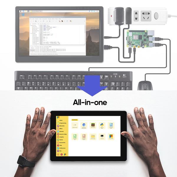
Single-board computers based on the Raspberry Pi are powerful, low-cost, and compact. This makes them excellent for small tasks that require a real computer rather than a low-level microcontroller. However, they have a minor downside in that, they are compact but not easily portable when given as a simple circuit board.

SunFounder offers a consumer-grade portable open-source tablet, RasPad 3. Built around the Raspberry Pi 4 SBC, the tablet provides a touchscreen platform for development and tinkering. It retains all of the Raspberry Pi’s ports, allowing you to take advantage of all of the Raspberry Pi’s features.

RasPad is intended to reduce barriers, allowing you to go right into building your maker’s project. The tablet can be easily assembled in few easy steps. It is a simple tablet interface that lets you program from anywhere. It is an excellent IoT project partner because it allows you to develop millions of applications.

Box Contents

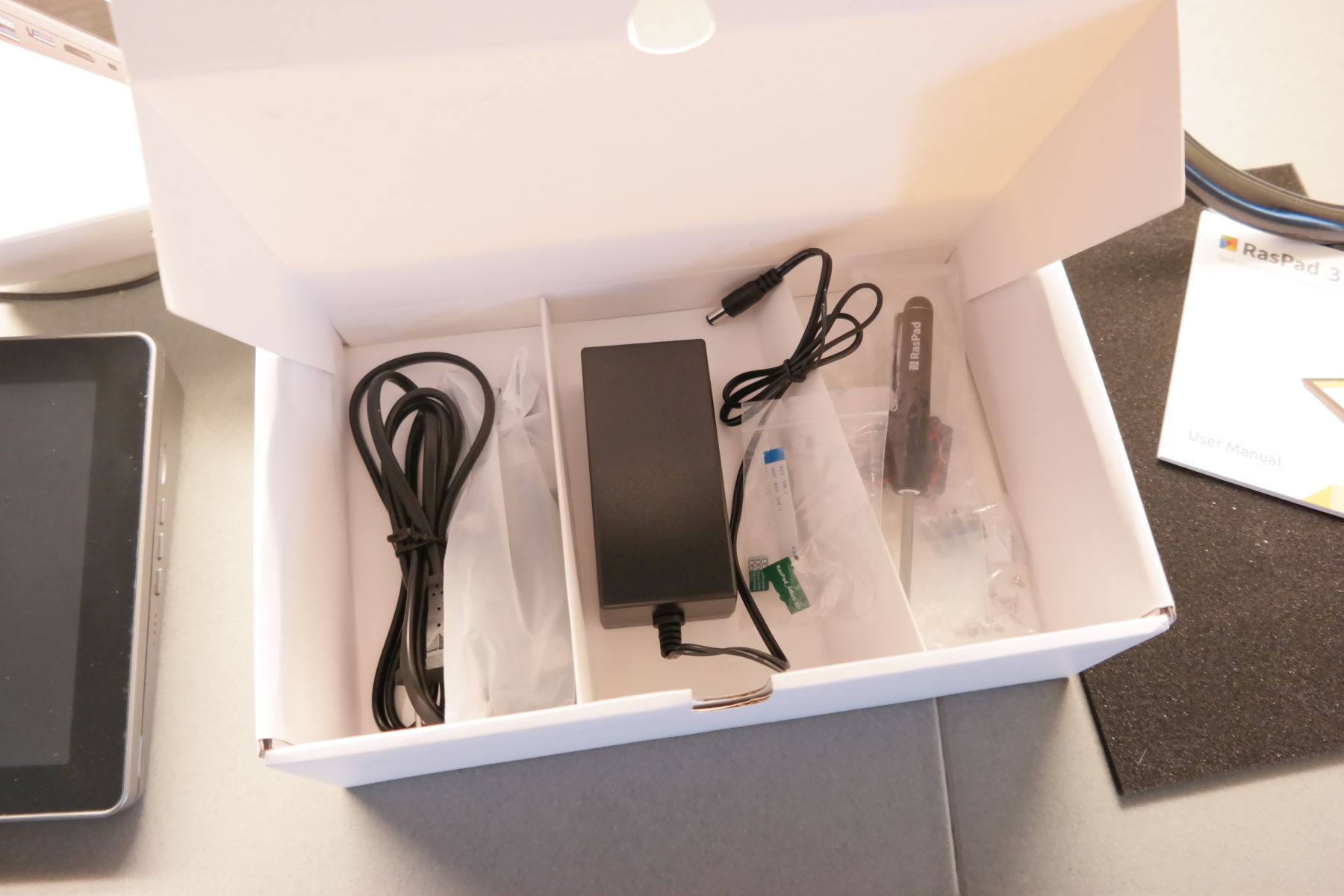
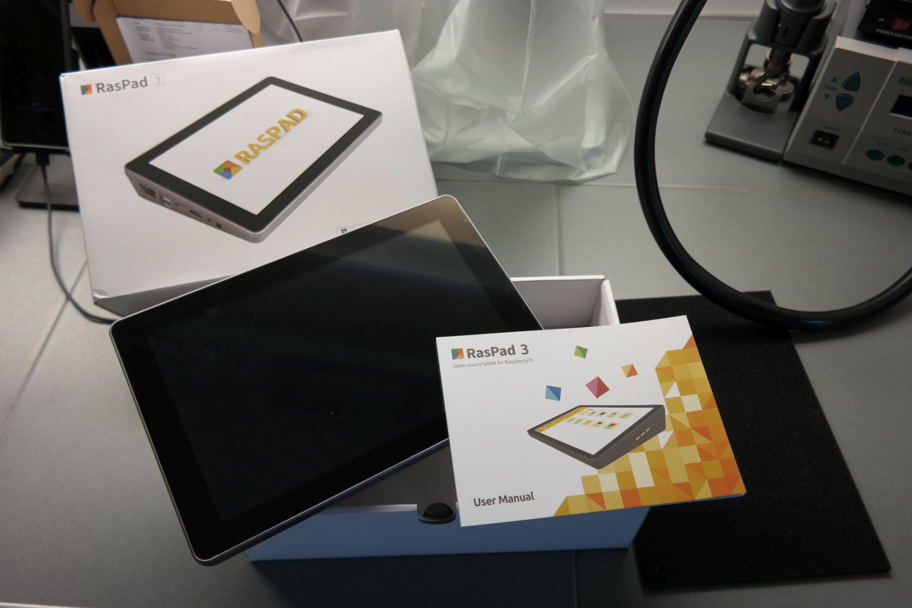
The RasPad 3 comes with everything you need to get started. The box includes all the essential parts and cables to self assemble the tablet. All you need is a Raspberry Pi 4B and a clean SD Card.

  • RasPad x 1
  • Power Adapter x 1
  • Micro SD Card Extension Board x 1
  • Fan x 1
  • FFC Cable x 1
  • Accel SHIM Module x 1
  • Heat Sink x 1
  • M2.5×9 Screw x 1
  • M2.5×4 Screw x 1
  • USB Cable x 1
  • Ethernet Cable x 1
  • HDMI Cable x 1
  • Type C Cable x 1
  • Micro HDMI Cable x 1
  • Power Cable x 1
  • Manual x 1

Assembly

Assembly is done using only a screwdriver and the process is fun and easy. All you have to do is to place the RB4 to its place and connect the provided cables to the daughterboard. This way all ports of the Raspberry Pi are available from the external. Don’t forget to also attach the 3 x small heatsinks to the board and the small fan to the back cover. This is all needed to start enjoying your new RB4 tablet.

Deeper Look at Portable Raspberry Pi Tablet

At 270 x 127 x 47 mm in footprint, the tablet has a 10.1 inch, 1280 x 800, IPS screen with 10-finger touch capability. It may not be the best screen you have seen for RB4, but it would definitely keep your eyes focused while programming or gaming. Thanks to its triangular structural design and a small six-axis acceleration sensor, it may also be put flat or upright on the table. Therefore, while using the Raspad OS, this allows for a rotating screen.

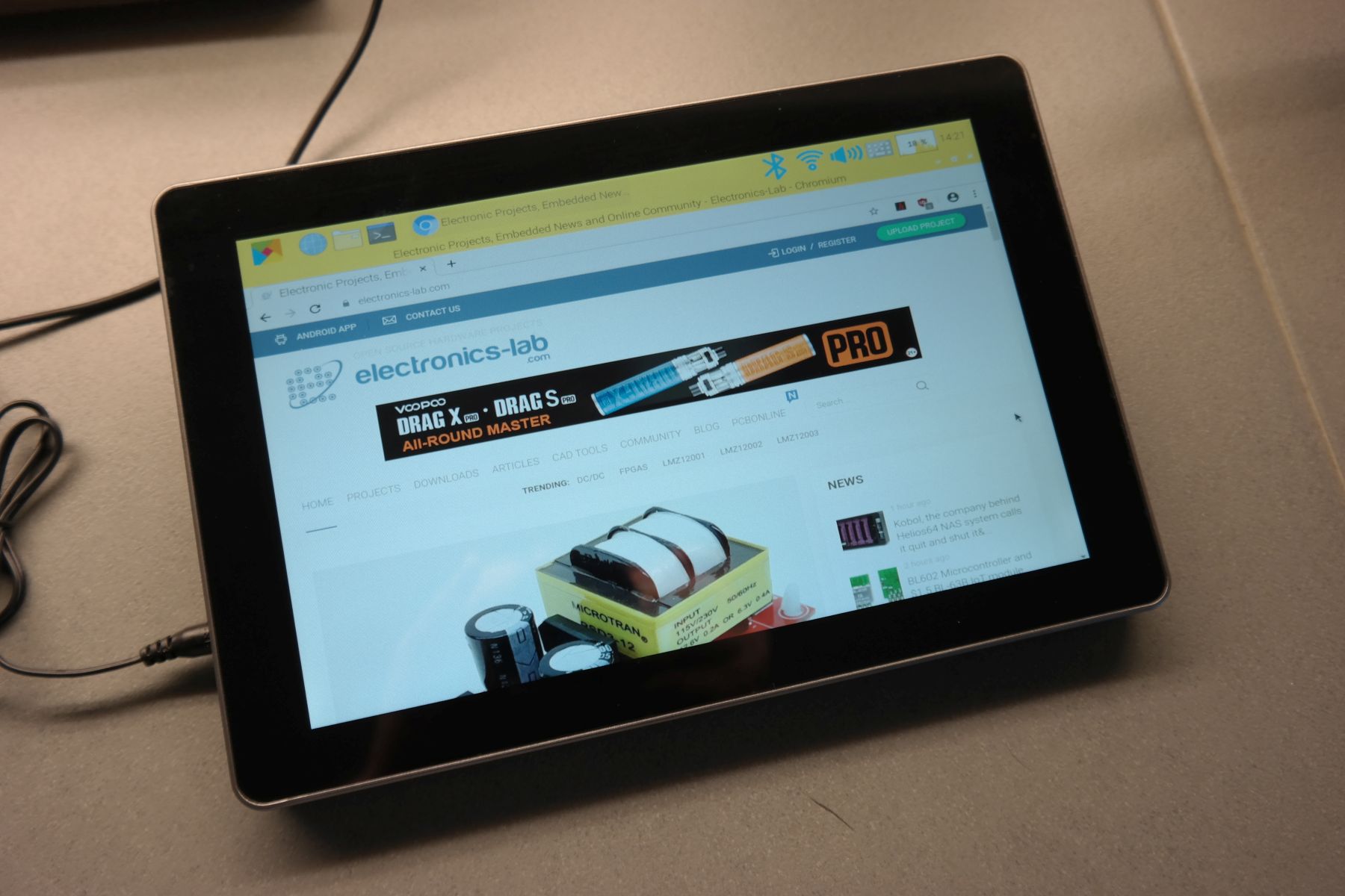
We also noticed that the image on the screen is a bit stretched on the horizontal axis, as this may be due to incorrect display drivers or the resolution of the LCD. You can notice this distortion in the last photo below. Check the electronics-lab.com logo, isn’t it distorted?

To create customized projects the tablet provides you access to all of the Raspberry Pi ports including Ethernet, HDMI, Audio, USB, and Power. In addition to this, RasPad can also be configured to include the Raspberry Pi 40-Pin I/O port for breadboarding and prototyping projects. Thus, like any other computer, you can connect the RasPad with other controllers.

Ports of RasPad 3
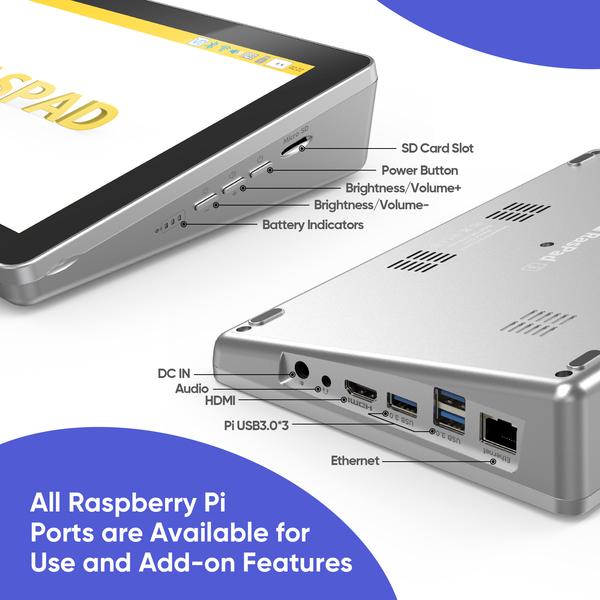
You can also simply extend RasPad with additional displays for enhanced multitasking or display mirroring by using HDMI ports. On the other side of the tablet, a small breakout board includes buttons for power, volume, and brightness control. Along with this, it has onboard LEDs for battery monitoring and an externally accessible microSD slot.

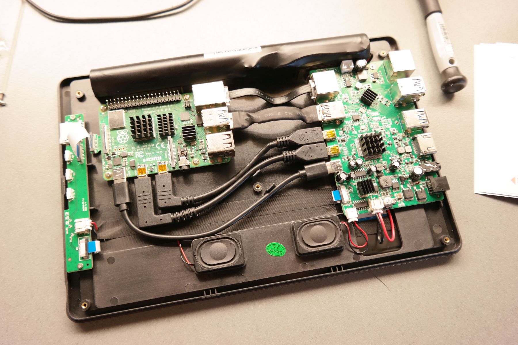
There are two boards inside. One is a custom board that connects the Raspberry Pi to the outside world, and the other is a battery management and On-Screen Display (OSD) control board. The Raspberry Pi 4 is placed between these two daughterboards. It connects to the custom board through three USB 3.0 ports, a USB 3.0 and Ethernet cable for wired networking, and two micro-HDMI cables. The dual micro-HDMI ports are for the onboard display and the external HDMI output, respectively.

Form Factor

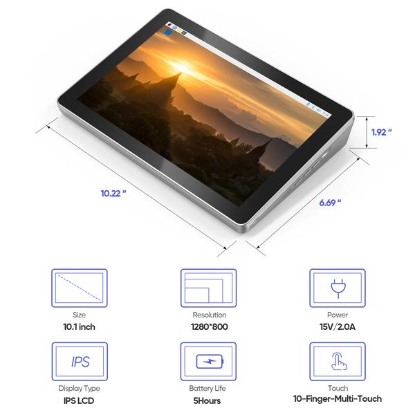
According to SunFounder, the tablet features a three-cell 3000mAh battery with a battery life of up to 5 hours. Although this may be over-rated, it should definitely keep you going for a few hrs, depending on the workload. Furthermore, the board powers the Raspberry Pi 4 through a USB-C connection. The inbuilt 18650 Lithium-polymer batteries or the 15V DC charger can provide the necessary power.

Additionally, the heatsinks are included to provide adequate cooling for most of the applications. According to Tom’s hardware article, the kit provides three heatsinks for the processor, a USB 3.0 controller, and a small accelerometer SHIM. Also, another upgrade over the original RasPad, the new RasPad 3 provides further cooling by a small fan, for additional cooling and if you want to overclock the Raspberry Pi to its limits. Fan proved to be quiet and not annoying at all.

Although the enclosure lacks GPIO pins, a small gap in the casing allows you to feed a ribbon cable through to expand the GPIO header to the outside world. Also, a TF card extension design has been introduced by the firm. Without removing the back cover, you may instantly swap out micro-SD cards to switch between OS.

Software of RasPad 3

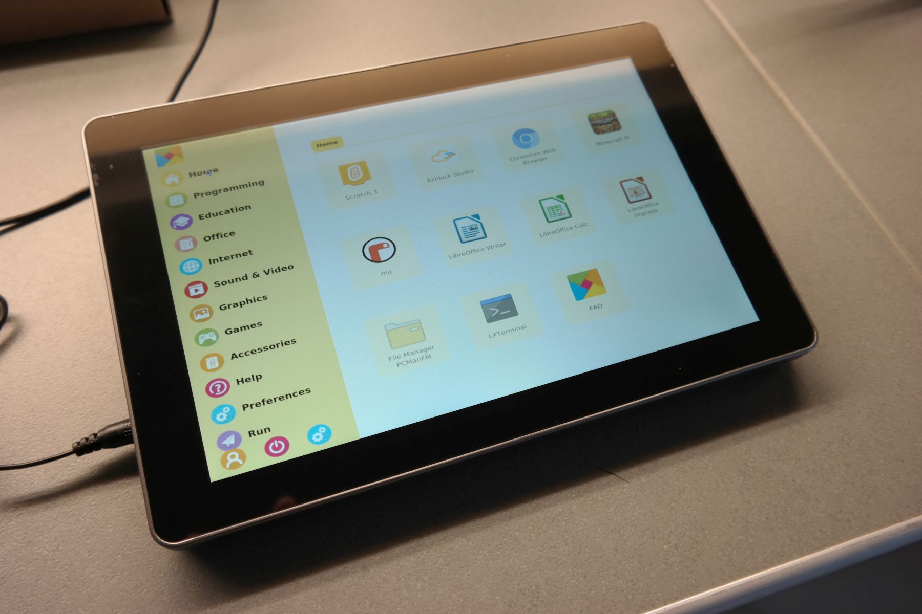
Talking about the software support, RasPad provides a fully customizable operating system environment. It is compatible with various operating systems, including Raspberry Pi OS, Ubuntu Desktop, Chromium OS, Windows, Android, and more. Additionally RasPad can be used as a 3D printer controller, a game console, a programming tablet, or a platform for developing Internet of Things (IoT) projects for smart-home applications.

The default available OS image is RasPad OS which is based on Raspberry Pi OS and is available for download on the official page. As we were informed from the manufacture they are planning to replace RasPad OS with RasPad launcher any time soon.

As you may already notice from the photos above, it integrates a custom user-friendly menu with multiple categories to make the different apps available.

RasPad 3 is available for $219 on the company’s website. For more information visit the product page. Images and technical specifications have been taken from the product page.

Dual Output Adjustable Linear Power Supply +/-1.2V to +/-12V @ 250mA

This project is a solution to power up most devices or projects requiring dual (+/-) adjustable power. The circuit consists of a stepdown transformer, bridge rectifier, DC filter capacitors, LM317 positive and LM337 negative adjustable voltage regulators, 2 x trimmer pot for independent output voltage adjust, and power LEDs.

Parts Explanation

  • Connector CN1 : 230V/115V AC Input
  • Jumper J2 : 230V Selection
  • Jumper J1 & J3 : 115V Selection
  • Transformer T1 : Step Down Transformer 12V-0-12VAC Output, 230V/115V AC Input
  • Bridge Rectifier BR1 : Rectifier Converts DC in to AC Supply
  • Capacitors C3, C5 : DC Filter Capacitors
  • LED D1 : +V PWR LED
  • LED D2 : -V PWR LED
  • Resistor R1, R2 : Current Limiting Resistors For LEDs D1 and D2
  • Regulator U1 : +V Adjustable Regulator
  • Regulator U2 : -V Adjustable Regulator
  • Trimmer Pot PR1 : +V Output Adjust +1.2V to +12V
  • Trimmer Pot PR2 : -V Output Adjust -1.2V to -12V
  • Capacitor C1, C2, C4, C6 : DC Filter Capacitors
  • Connector CN2 : Adjustable DC Output
Note1: This power supply supports 230V AC or 115V AC input, Jumpers are located under PCB for input voltage selection, remove input power cable while changing Jumper selection.
Note 2: This power supply contains hazardous voltage at the input, PCB must be installed in an encloser that prevents accidental contact. Use Plastic screws to mount the PCB
Note 3: Heatsink is a must for regulators U1 and U2 @ full load, the heatsink should be mounted with plastic screws and should not touch the ground plane of the PCB.
Note 4: It is advisable to set the output voltage using PR1 and PR2 before connecting the output to the load.

Input Voltage Selection

  • For 230V AC Input: Close Jumper J2, Jumper J1, and J3 Open
  • For 115V AC Input: Close Jumper J1 and J3, Jumper J2 Open

Other Similar AC to DC Power Supplies

Features

  • Input 230V or 115V AC (Use Jumpers to Select 230V or 115V AC)
  • Output +/-1.2V to 12V DC (Dual Output)
  • Output Ripple Approx. 5mV
  • Maximum Load Current 500mA (250mA + 250mA)
  • 2 X Power LEDs, for +V and -V
  • Screw Terminal for AC Input
  • Screw Terminal for Regulated DC Output
  • PCB Dimensions 91.76 x 43.82 mm

Schematic

Parts List

NOQNTY.REF.DESC.MANUFACTURERSUPPLIERSUPPLIER PART NO
11BR1BRIDGE RECTIFIER W10M MICRO COMMDIGIKEYW10M-BPMS-ND
21CN13 PIN SCREW TERMINAL PITCH 5.08MMPHOENINXDIGIKEY277-1248-ND
31CN23 PIN SCREW TERMINAL PITCH 5.08MMPHOENIXDIGIKEY277-1248-ND
42C1,C610uF/25V SMD SIZE 1206MURATA/YAGEODIGIKEY
52C2,C40.1uF/50V SMD SIZE 0805MURATA/YAGEODIGIKEY
62C3,C51000uF/25V OR 2200/25VPANASONICDIGIKEYP13121-ND
71D1RED LED SMD SIZE 0805LITE ONDIGIKEY160-1427-1-ND
81D2GREEN LED SMD SIZE 0805DIALIGHTDIGIKEY350-2044-1-ND
93J1,J2,J3JUMPER(PCB SOLDER) USE SMD 0-OHM RESISTOR SIZE 1206DIGIKEYPCB JUMPERS
102PR1,PR25K TRIMMER POTBOURNSDIGIKEY3362H-502LF-ND
112R1,R21.5K 5% SMD SIZE 0805MURATA/YAGEODIGIKEY
122R3,R4220E 1% SMD SIZE 0805MURATA/YAGEODIGIKEY
131T1TRANSFORMER 3FD-424TAMURADIGIKEYMT2115-ND
141U1LM317-ADJ TO 220STDIGIKEY497-1575-5-ND
151U2LM337-ADJ TO 220STDIGIKEY497-1585-5-ND
162HEATSINK -TO220 AVIDDIGIKEYHS106-ND
172M3 X 10MM SCREW AND NUT FOR TO220 HEATSINK/REGULATORIO AUDIODIGIKEY1937-IO-M3X10/M3HN-50-ND

Connections

Gerber View

Photos

Video

LM317 Datasheet

Dual +12V/-12V @ 400mA Regulated Linear Power Supply with AC input

The project presented here is a dual output linear power supply. This power supply provides low ripple low noise DC regulated output. It is a very useful tool to power Audio, Video, OPAMP-based circuits, and projects. The circuit provides regulated +/-12V DC output @ 400mA + 400mA. The project supports AC input supply 230V or 115V. On-board jumpers are provided for AC230V or AC115V selection. Besides regulated output, the board also has provisions to output the unregulated supply using CN2.

Parts Explanation

  • Connector CN1: 230V/115V AC Input
  • Jumper J2:  230V Selection
  • Jumper J1, J3: 115V Selection
  • Transformer-Step Down T1: 230/115V AC IN, 12VAC-0V-12VAC 0.83A
  • Bridge Rectifier BR1: Bridge Rectifier
  • Capacitor C2, C5: DC Filter Capacitors
  • Connector CN2: Unregulated DC Output
  • Regulator U1: +12V Regulator
  • Regulator U2: -12V Regulator
  • C1,C3,C4, C6 : DC Filter Capacitors
  • LED D1: +12V LED
  • LED D2: -12V LED
  • Connector CN3, and CN4: +/-12V Regulated Output
  • Resistor R1, R2: Current Limiting Resistors for LEDs
Note1: This power supply supports 230V AC or 115V AC input, remove input power cable while changing Jumper selection.
Note 2: This power supply contains hazardous voltage at the input, PCB must be installed in an encloser that prevents accidental contact. Use Plastic screws to mount the power supply.
Note 3: Power supply also can be used as Dual Regulated +/-15V DC Output. In this case replace U1 LM7815, U2 LM7915

Note 4: Heatsink is a must for regulators U1 and U2 @ full load. The heatsink should be mounted with plastic screws and should not touch the ground plane of the PCB.

Input Voltage Selection

  • For 230V AC Input: Close Jumper J2 Jumper J1 and J3 Open,
  • For 115V AC Input: Close Jumper J1 and J3 Open Jumper J2

Other Similar AC to DC Power Supplies

Features

  • Input 230V or 115V AC (Use Jumpers to Select 230V or 115V AC)
  • Output +/-12V DC (Dual Output)
  • Unregulated Output Approx. +/-17V (CN2)
  • Output Ripple Approx. 5mV
  • Maximum Load Current 800mA (+12V@400mA, -12V@400mA)
  • 2 x Power LEDs, for 12V and -12V
  • Screw Terminal for AC Input
  • Screw Terminal for Regulated DC Output
  • 3 Pin Male Header Provides Unregulated DC Output
  • 4 Pin Male Header for Regulated DC Output
  • PCB Dimensions 99.06 x 58.74 mm

Schematic

Parts List

NOQNTY.REF.DESC.MANUFACTURERSUPPLIER SUPPLIER PART NO
11BR1BRIDGE GBL08 OR GBL06VISHAYDIGIKEYGBL06-E3/45GI-ND
21CN13 PIN SCREW TERMINAL PITCH 5.08MMPHOENIXDIGIKEY277-1248-ND
31CN23 PIN MALE HEADER PITCH 2.54MMWURTHDIGIKEY732-5316-ND
41CN34 PIN MALE HEADER PITCH 2.54MMWURTHDIGIKEY732-5317-ND
51CN43 PIN SCREW TERMINAL PITCH 5.08MMPHOENIXDIGIKEY277-1248-ND
62C1,C40.1uF/50V SMD SIZE 0805MURATA/YAGEODIGIKEY
72C2,C52200uF/25VRUBYCONDIGIKEY1189-3651-ND
82C3,C610uF/25V SMD SIZE 1206MURATA/YAGEODIGIKEY
91D1RED LED SMD SIZE 0805LITE ONDIGIKEY160-1427-1-ND
101D2GREEN LED SMD SIZE 0805DIALIGHTDIGIKEY350-2044-1-ND
113J1,J2,J3JUMPER 2 PIN MALE HEADER PITCH 2.54MMWURTHDIGIKEY732-5315-ND
122R1,R21.5K 5% SMD SIZE 0805MURATA/YAGEODIGIKEY
131T1VPP24–830 TRANSFORMER 12V-0-12VACTRIADDIGIKEY237-1071-ND
141U1LM7812TIDIGIKEY296-50628-ND
151U2LM7912TIDIGIKEYLM7912CT/NOPB-ND
162SHUNTSHUNT FOR JUMPPERS J1,J2,J3SULLINSDIGIKEYS9001-ND
172HTHEATSINK AVIDDIGIKEYHS106-ND
182SCM3 SCREW X 10MM LIO AUDIODIGIKEY1937-IO-M3X10/M3HN-50-ND

Connections

Gerber View

Photos

Video

LM7812 Datasheet

Dual +5 V/-5V @ 200 mA Regulated Linear Power Supply

The project presented here is a dual AC to DC output linear power supply. This power supply provides low ripple low noise DC regulated output. Usually, transformer-based linear power supplies are considered very bulky and inefficient, but this power supply still is very important for sensitive applications such as analog circuits, communications devices, radio devices, audio circuits, OPAMP-based projects etc.

CN1 is AC input, Jumper J2 for 230V AC input, Jumper J1/J3 for 115V AC, Transformer T1-Step down transformer provides 6.3V-0V-6.3V AC Outputs, Bridge Rectifier BR1 converts AC into DC, Capacitor C2/C4 DC filter capacitors, CN2 unregulated DC output approx. +/-9V DC, U1 +5V regulator, U2 -5V regulator, D1 +5 power LED, D2 -5V power LED, R1/R2 current limiting resistors for LEDs, C1/C3/C5/C6 output DC capacitors, CN3 Male header +/-5V regulated output, CN4 screw terminal +/-5V regulated output.

Dual +5 V/-5V @ 200 mA Regulated Linear Power Supply – [Link]

Low Voltage Microphone Preamplifier with Variable Compression and Noise Canceling

This is a complete microphone signal conditioning project. Designed primarily for voice-band applications, this project provides amplification, limiting, variable compression, and noise gate. User-adjustable compression ratio, noise gate threshold, and two different fixed gains optimize circuit operation for a variety of applications.

This is a complete and flexible solution for conditioning condenser microphones for personal electronics and computer audio systems. It is also excellent for improving vocal clarity in communications and the public address systems. A low noise voltage-controlled amplifier (VCA) provides a gain that is dynamically adjusted by a control loop to maintain a set compressions characteristic.  The compression ratio is set by a jumper and can be varied from 1:1 to over 10:1 relative to the fixed rotation point. Signals above the rotation point are limited to prevent overload and eliminate popping.

A downward expander (noise gate) prevents the amplification of background noise or hum. This results in an optimized signal level prior to digitization, thereby eliminating the need for additional gain or attenuation in the digital domain. The flexibility of setting the compression ratio and the time constant of the level detector, coupled with two values of rotation point, make the SSM2167 easy to integrate into a wide variety of microphone conditioning applications.

Low Voltage Microphone Preamplifier with Variable Compression and Noise-Canceling – [Link]

IR Remote Controlled Motorized Potentiometer – Arduino Compatible

This is an Infrared Remote controlled motorized potentiometer controller. It’s an open-source project built on the Arduino platform and compatible with Arduino IDE for custom programming. The project consists ATMEGA328 microcontroller, IR sensor, L293D motor driver, ALPS Motorized potentiometer, a connector for Arduino programming, etc. The L293D H-bridge drives the potentiometer motor, 2 Parallel direction pins are used to change the motor direction which moves the POT in a forward or reverse direction.

IR Remote Controlled Motorized Potentiometer – Arduino Compatible – [Link]

onsemi / Fairchild FAN53526 Programmable TinyBuck® Regulators

onsemi / Fairchild FAN53526 Digitally Programmable TinyBuck® Regulators are switching voltage regulators that provide a digitally programmable output from an input voltage supply of 2.5V to 5.5V. The FAN53526 has an output voltage programmed through an I2C interface capable of operating up to 3.4MHz. The FAN53526 utilizes a proprietary architecture with synchronous rectification delivering 3.0A continuous at over 80% efficiency, maintaining that efficiency at load currents as low as 10mA.

The onsemi / Fairchild FAN53526 Digitally Programmable TinyBuck Regulators have a nominal fixed frequency of 2.4MHz, allowing a reduction of the value of the external components. To improve regulation, additional output capacitance is added without affecting stability. Pulse Frequency Modulation (PFM) operates in Power-Save Mode at moderate and light loads with a typical quiescent current of 50A at room temperature. At higher loads, the system automatically switches to fixed−frequency control, operating at 2.4MHz. In Shutdown Mode, the supply current drops below 1A, reducing power consumption. PFM Mode can be disabled if a fixed frequency is desired.

The FAN53526 is housed in a 15-bump, 1.310mm x 2.015mm, 0.4mm ball pitch WLCSP.

Features

  • 2.4MHz Fixed frequency operation
  • Reduces the number of external components
  • Best-in-class load transient
  • Additional output capacitance can be added to improve regulation during load transients without impacting stability
  • I2C-Compatible interface up to 3.4Mbps
  • Flexible interface
  • 3.0A Continuous output current
  • 2.5V to 5.5V Input voltage range
  • 0.6V to 1.39375V in 6.25mV steps digitally programmable output voltage
  • Programmable slew rate for voltage transitions
  • PFM mode for high efficiency in light-load
  • 50uA (Typical) quiescent current in PFM mode
  • Input Under−Voltage Lockout (UVLO)
  • Thermal shutdown and overload protection
  • 15-Bump Wafer-Level Chip Scale Package (WLCSP)

Typical Application

more information: https://www.onsemi.com/products/power-management/dc-dc-power-conversion/converters/fan53526

TOP PCB Companies