Recent news reaching us is that Helios4 and Helios64 manufacturer, Kobol, has decided to call it quits promising to only give its support to its customers when available.
The three-man company behind the popular open-spec network-attached storage (NAS) devices made this announcement shortly after it returned from a two-month break which it took in April.
“We have decided to stop the adventure here,” says Kobol as they break the news to their customers in a recent statement. “Quite a few reasons made us come up with this difficult decision, but it all comes down to two key points,” they said. “There is still ongoing difficulties to manufacture electronics, to procure parts and mainly to control costs. [And] we made a rookie mistake of stretching ourselves very thin last year with the first delivery of Helios64 while being just a three-men show. We should have brought a few more people onboard sooner, but we waited too long until we were a bit burnt out,” they added.
Helios64 network-attached storage system was first unveiled by Kobol about two years ago as a follow-up to its considerably more blocky Helios4 system. The stylish five-bay open-spec NAS system was initially supposed to be powered by a Rockchip RK3399K processor but was later stepped down to a slower version due to the shortage of components during COVID-19. There were also other issues that came along when the system was finally launched — ranging from a faulty Ethernet port to drive sleds which were slightly too big to fit in the chassis and then to other bigger concerns that possibly came from rushed software updates — which according to guesses were part of what led the three-man team to shut its doors.
Meanwhile, this big decision by the team has left those who have bought a Helios64 with quite an uncertain future, especially as no one knows what the next line of action will be. There is also uncertainty as to when there would be a second production run of the system hardware as well as newer revisions that will see to the fixing of some or all of the design flaws.
Thankfully, they did not completely throw in the towel as the team also said it will try to give its support to its customers when available. It promised to “post on the wiki all the blueprints of Helios64 [to] help people tinker or even troubleshoot their board when necessary.”
We really do not know what’s next for them, but if we get any further tips on this matter, we will be sure to give updates.
Bouffalo Labs BL602 microcontroller is a Wi-Fi and Bluetooth LE-capable microcontroller with a 32-bit RISC-V derived core. The chipset is designed for ultra-low-cost low-power applications and has support for 2.4G radio, Wi-Fi 802.11b/g/n and BLE 5.0 baseband/MAC designs. It also has support for a variety of safety and security features.
The BL602 microcontroller might not be able to stand side by side with the ESP8266 in terms of price but it definitely has more features, more memory, and more storage. We also learned that a Hong-Kong based organization known as Pine64 is currently making some efforts to reverse engineer the microcontroller for a fully open-source blob-free wireless implementation.
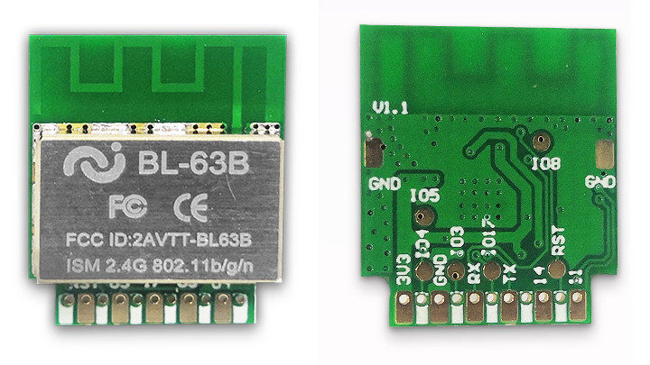
BL-63B IoT Module
Several boards have been built around this BL602 microcontroller like the DT-BL10 development board, the PineCone BL602 board, and the new BL-63B – a more compact module that offers many possibilities at a more favorable price.
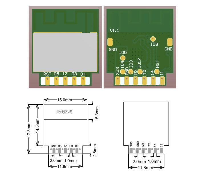
The BL-63B is a highly integrated single-chip low-power 802.11n wireless local area network (WLAN) network controller. It has a low power consumption rate with high performance and support for various safety functions. The 17.3 mm x 15 mm x 3mm module also features a number of configurable general purpose IOs, which are configured as digital peripherals for different applications and control purposes.
Some of the key features and specifications of the BL63B module include:
High performance
Low power consumption
Support for safety functions
Integrates internal memory for complete WIFI protocol functions
Microcontroller: Bouffalo Labs BL60232-bit RISC-V processor running at up to 192 Mhz, with:
276KB RAM
128KB ROM
1 Kbit eFuse,
Embedded flash (optional)
4x DMA channels, and,
Wireless subsystem that contains 2.4G radio, Wi-Fi 802.11b/g/n and Bluetooth Low Energy 5.0 baseband / MAC designs
2MB flash
2.4GHz 802.11b/g/n WiFI 4 1×1 SISO up to 65 Mbps (802.11n) or 26 Mbps (802.11g)
Bluetooth Low Energy (BLE) 5.0
PCB antenna
Up to 5x General Purpose IO (GPIO), UART, ADC, DAC, PWM, I2C, SPI, IR, Reset, 3.3V and GND
2x additional test pads for GND, IO8 and IO5
Power supply: 3.0 to 3.6V
Dimensions: 17.3 mm x 15 mm x 3mm
Operating Temperature Range: -30°C to +85°C
FCC ID: 2AVTT-BL63B
The BL-63B module is currently available and sells for $2.5 per piece on Taobao in China. However, if you are purchasing as many as 1000 pieces, you would qualify for some discounts and be able to purchase one piece for only $1.5. You can also buy this device on the LCSC Electronics page.
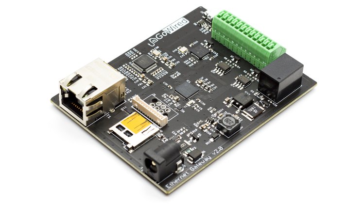
GoWired Multiprotocol Gateway is an evolution of one of our previous boards, the GetWired Ethernet Gateway, with more power, more features, more versatility, and better solutions for wired automation systems. It features powerful ARM M0+ microcontroller with eight times more ROM and 16 times more RAM memory. We doubled the RS485 transceiver to be able to utilize two different communication protocols at once (MySensors, MODBUS, etc.) and added a CAN transceiver, since it is also widely used in home automation. USB obviously must be included too. To ensure reliable Ethernet communication, we utilized a market-leading Wiznet W5500 chip. Microcontroller internal memory can be expanded by an SD card, e. g. for the purpose of gathering debug information.
GoWired Multiprotocol Gateway also features improved power supply circuitry which now can handle voltage ranges from 7-26 VDC. Onboard current and power monitor can regularly share power-related data, along with other information about the status of the device. This information might be displayed using an e-ink screen, for example. All this is designed with reliability and safety in mind, in general, and in terms of power (ESD, overcurrent, overvoltage, reverse polarity protection) and EMC & EMI precautions, specifically. The device fits in a compact, four-slot DIN rail enclosure.
Hardware Specifications
Powerful 32-bit ATSAMD21G18A ARM M0+ microcontroller with 32 kB RAM and 256 kB ROM, 48 MHz
Reliable Wiznet W5500 Ethernet transceiver with hardware TCP/IP stack
Support for three different communication standards (RS485, CAN, USB) and four different protocols in the same time (doubled RS485 transceiver)
Power and current monitoring for all connected devices (if the devices are powered from the Gateway)
uSD card slot for debug and other purposes
Designed with EMC & EMI protection in mind
Protected against ESD, overcurrent, overvoltage, reverse polarity
Extension board with e-ink display, LEDs and buttons mounted on the enclosure
four-slots DIN rail enclosure
Software Features
Compatible with Arduino
Open source, modifiable, configurable, ready to use
Plug & play compatible with most open source home automation controllers (Domoticz, Home Assistant, etc.)
Privacy friendly, can work without internet access, doesn’t require any cloud services
Open Source Software
Our open source software is compatible with Arduino, includes a custom board definition, and can be modified according to the user’s needs. Most importantly GoWired Multiprotocol Gateway is ready to use out-of-the-box and is plug & play compatible with the vast majority of open source home automation controllers (e. g. Home Assistant, Domoticz). We also have plans for extended software versions to be developed in the future. Our software is located on GitHub.
We have witnessed an increase in natural disasters worldwide in recent months. Wildfires, earthquakes, storms, floods and droughts have left many people’s homes in ruins. These extreme natural events often have serious consequences in terms of economic losses, social chaos as well as environmental damage.
Nowadays, enhanced technologies offer innovative ways to address various problems around the world, especially in mission-critical situations. For example, unmanned aerial vehicles (UAVs), also known as drones, can effectively act as mobile sensors in the IoT environment, collecting data and relaying it back to the cloud app or other analytics services. As the drone industry has expanded over the last several years, many sectors has been adopting drones for work for security and emergency response.
UAV Applications in Critical Situation
Natural Disasters
Drones are able to explore and report on locations that may be inaccessible via other means, which has become the key during and after the disasters. To begin with, ordinary modes of transport are often not viable in such cases, and drones will come in handy to help prevent a worst-case scenario. They are able to easily fly over disaster sites and deliver medical supplies such as small aid packages. In addition, drones can also be used to help first responder teams to evaluate the situation of the incidents, such as wildfires and floods, locate injured people and therefore mitigate damage from these natural disasters.
Public Safety
Deploying UAVs in emergency situations enhances the work efficiency for law enforcement teams, helps to improve public safety, increase reliability and decrease response times. Currently drones are used by police forces in a number of applications, including but not limited to surveillance in large open areas, negotiating hostage situations and investigating bomb threats. Compared with helicopters, UAVs are innovative, cost-effective and readily available. More importantly, they enable police officers to handle potentially dangerous situations while protecting their own safety.
Remote Workplaces
The inspection and maintenance of industrial facilities often brings many challenges and health risks to the workers. When in-person inspection is needed, using drones instead of people to collect data can have a huge impact on personal safety. It eliminates the need for employees to be exposed to distanced or potentially dangerous situations, such as inspecting construction sites, boilers, mines, power grids, tunnels and so on. By using sensors and cameras, the drones collect data and transmit it to the inspector in real time. As a fast, safe and economical way, drone helps with the maintenance on infrastructure or device repairs instead of using human resources or heavy machinery.
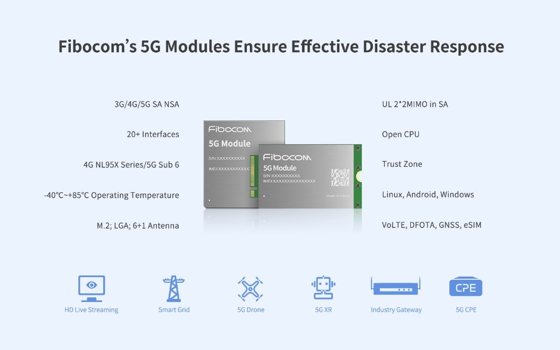
Fibocom Wireless Solutions Empower Drones Industry
Drone technology, combined with robust connectivity solutions, is helping to building a safer future, the realization of which requires high-speed and stable wireless connectivity. Embedded in drones, Fibocom is able to offer wireless communication modules to accelerate the use of drone in mission-critical situations and to establish a smarter, safer society.
Take UAV inspection as an example. UAV inspections are mainly used for grid maintenance through drone cameras to access remote areas easily. With 5G’s high speed and network capacity, Fibocom’s 5G wireless modules enable the data transmission of high-definition (4K/8K) videos which require high bandwidth of over 100Mbps. These devices transmit a crystal-clear view of the maintenance area, making it easier to identify problems in emergency repair scenarios, reducing labor costs and grid downtime.
Fibocom’s 5G wireless communication modules are designed to offer eMBB (enhanced Mobile Broadband), URLLC (Ultra Reliable and Low Latency Communications), as well as mMTC (massive Machine Type Communications). Supporting 5G standalone network (SA) and non-standalone (NSA) network architectures, Fibocom 5G wireless module series supports the Sub-6GHz and mmwave bands, and is compatible with 5G NR, LTE and WCDMA standards. It eliminates customers’ investment concerns at the initial stage of 5G construction, responding to the commercial demand for rapid landing. Meanwhile, Fibocom 5G modules come with a rich set of interfaces including USB3.1 (3.0), USB2.0, PCIe3.0 (2.0), SPI, SDIO, GPIO, UART, etc. It has been certified by various regional operators, industry associations and local regulation, satisfying different deployment requirements for customers worldwide.
Although IoT solutions may not stop disasters, the flexibility and coverage of wireless networks, together with the reliability and resilience of IoT, can create new ways to build a safer community.
Watch how Fibocom is bringing connectivity to more industries, more devices, and more applications:
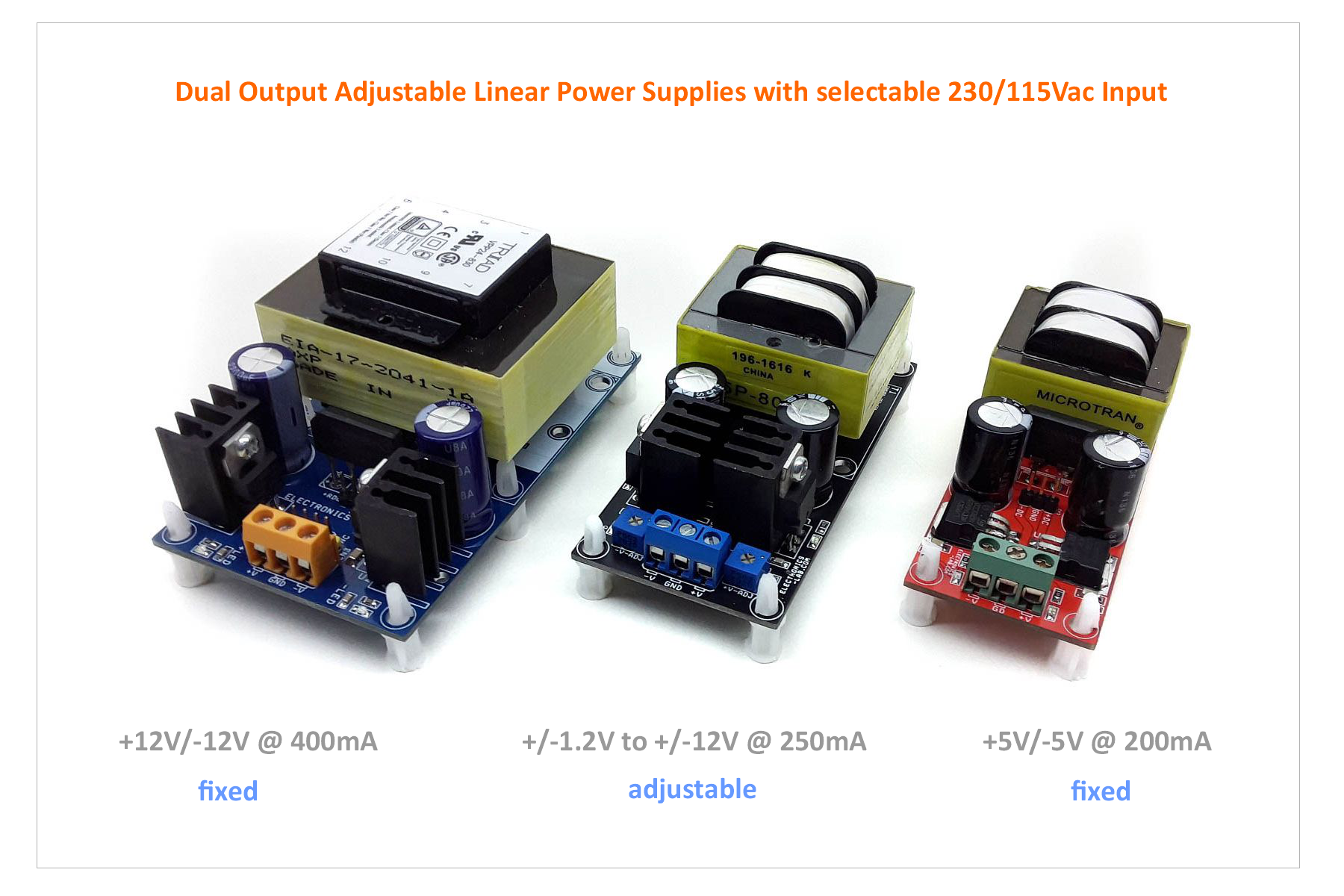
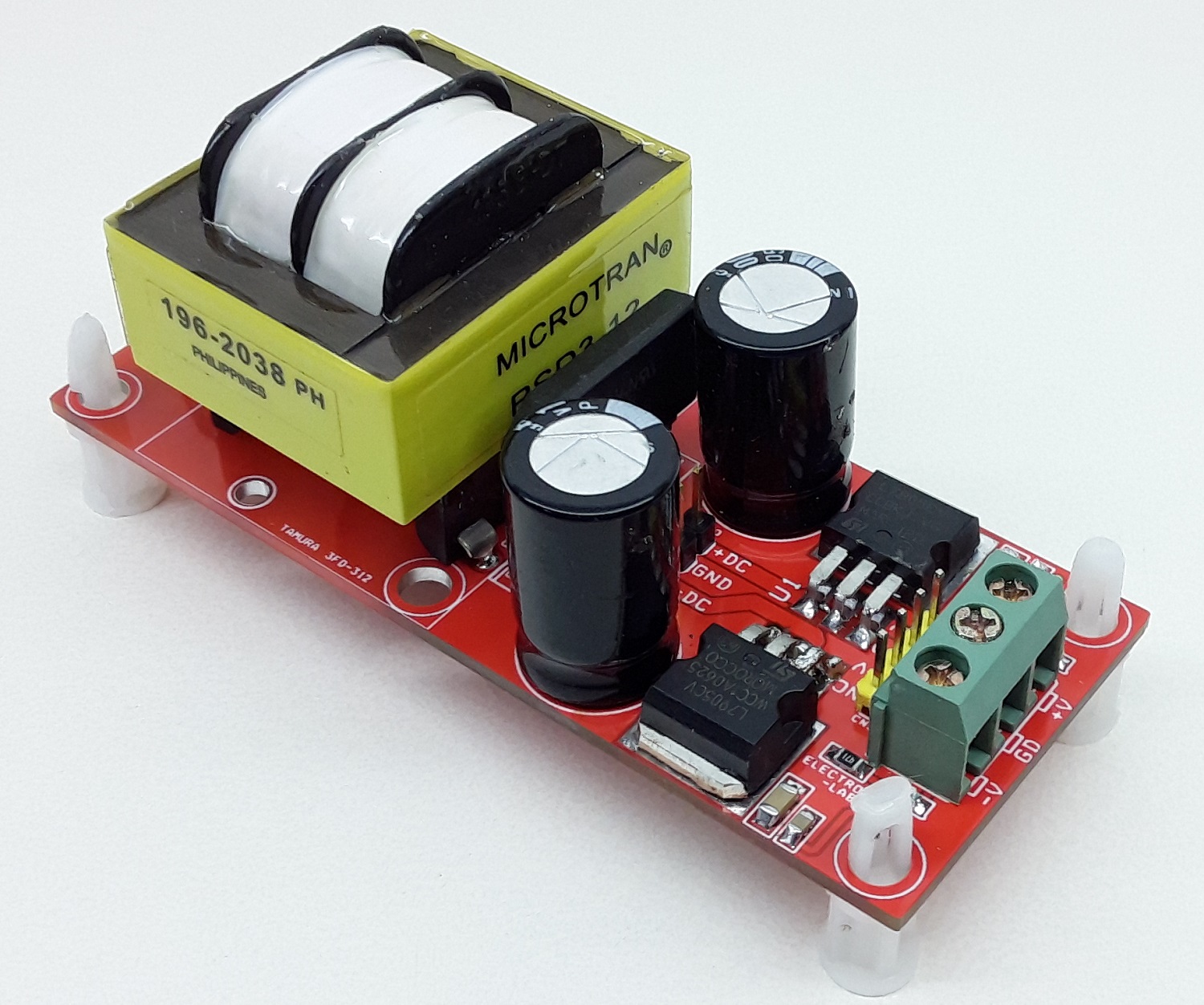
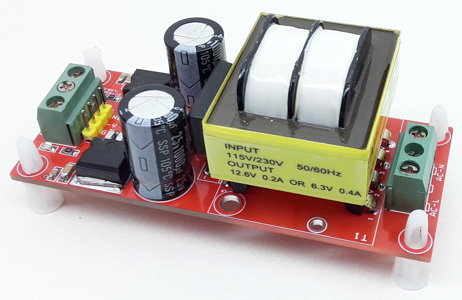
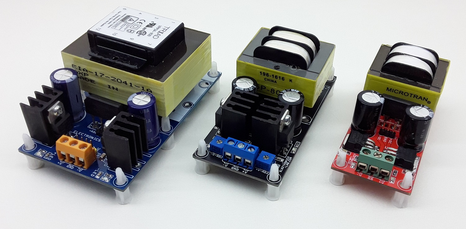
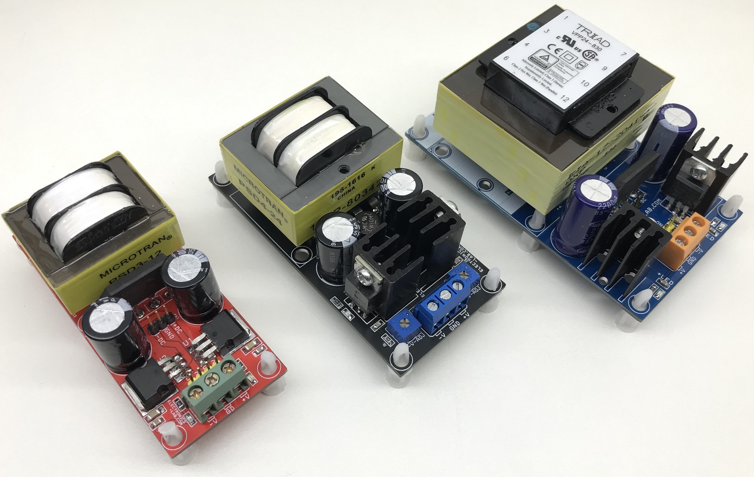
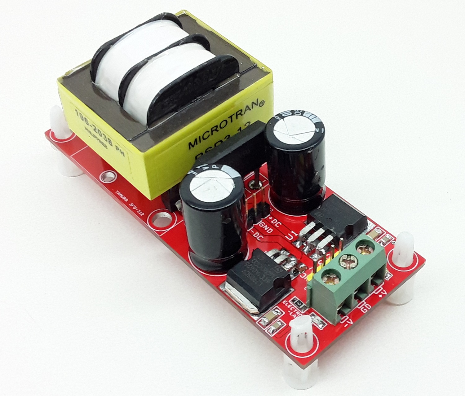
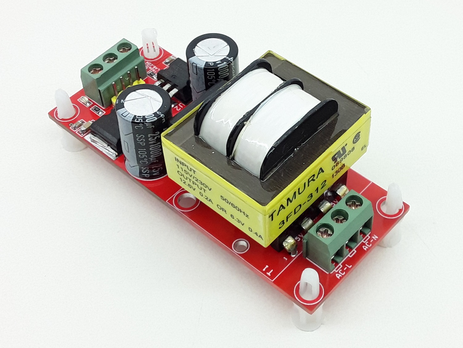
The project presented here is a dual AC to DC output linear power supply. This power supply provides low ripple low noise DC regulated output. Usually, transformer-based linear power supplies are considered very bulky and inefficient, but this power supply still is very important for sensitive applications such as analog circuits, communications devices, radio devices, audio circuits, OPAMP-based projects etc.
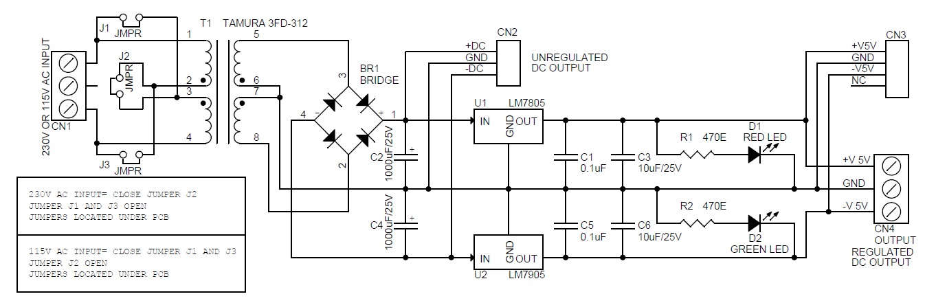
Parts Explanation
CN1 is AC input
Jumper J2 for 230V AC input
Jumper J1/J3 for 115V AC
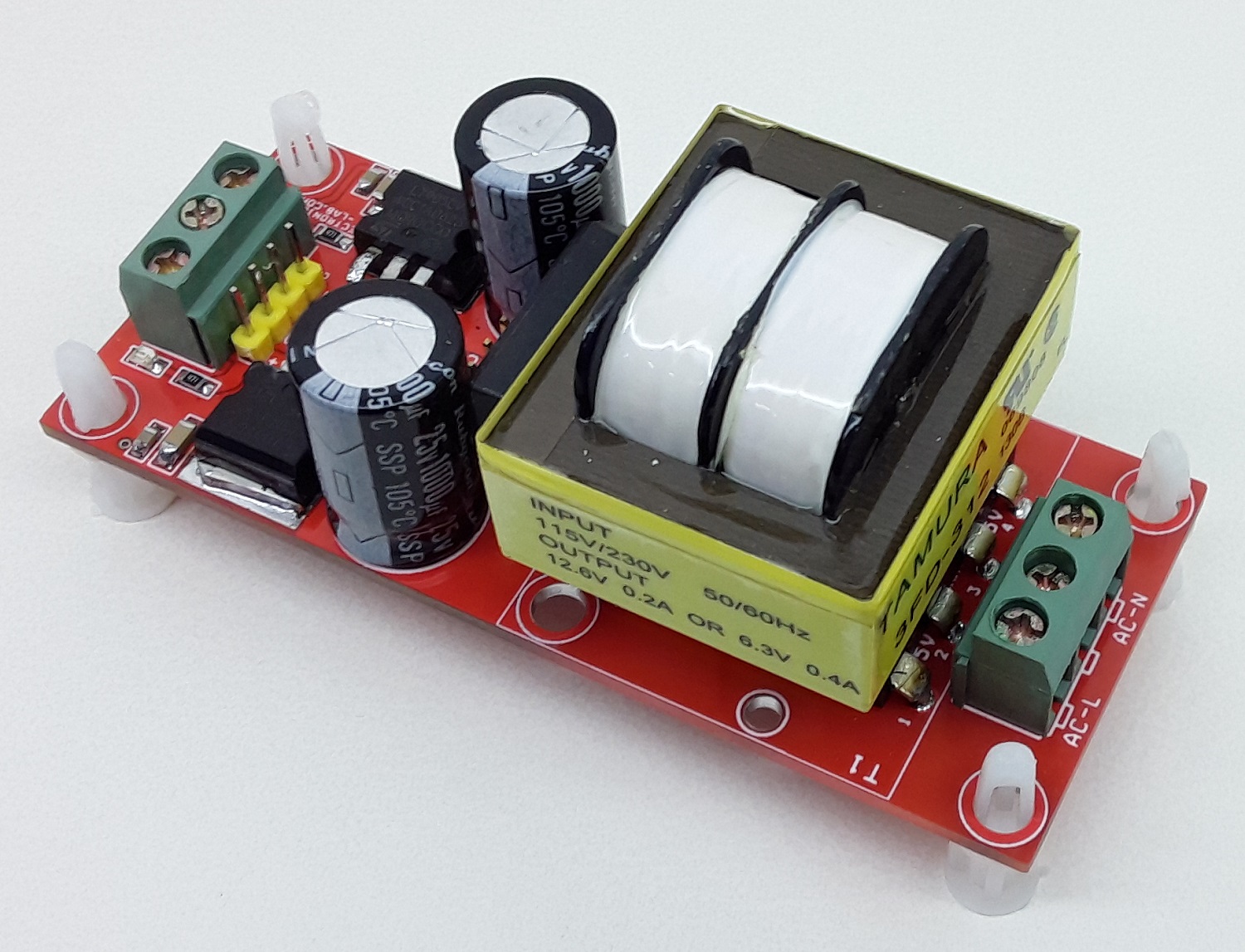
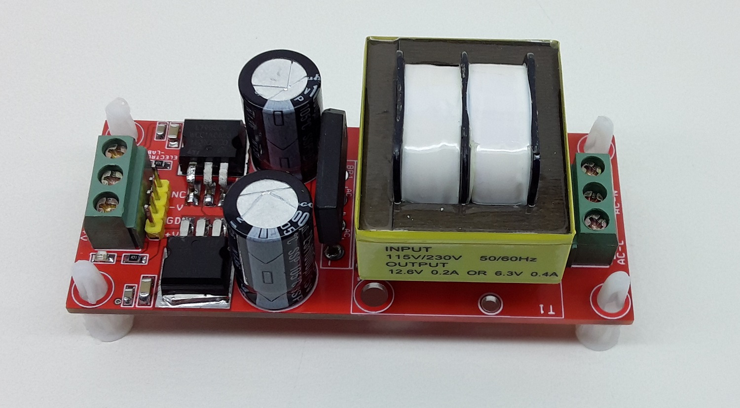
Transformer T1-Step down transformer provides 6.3V-0V-6.3V AC Outputs
Bridge Rectifier BR1 converts AC into DC
Capacitor C2/C4 DC filter capacitors
CN2 unregulated DC output approx. +/-9V DC
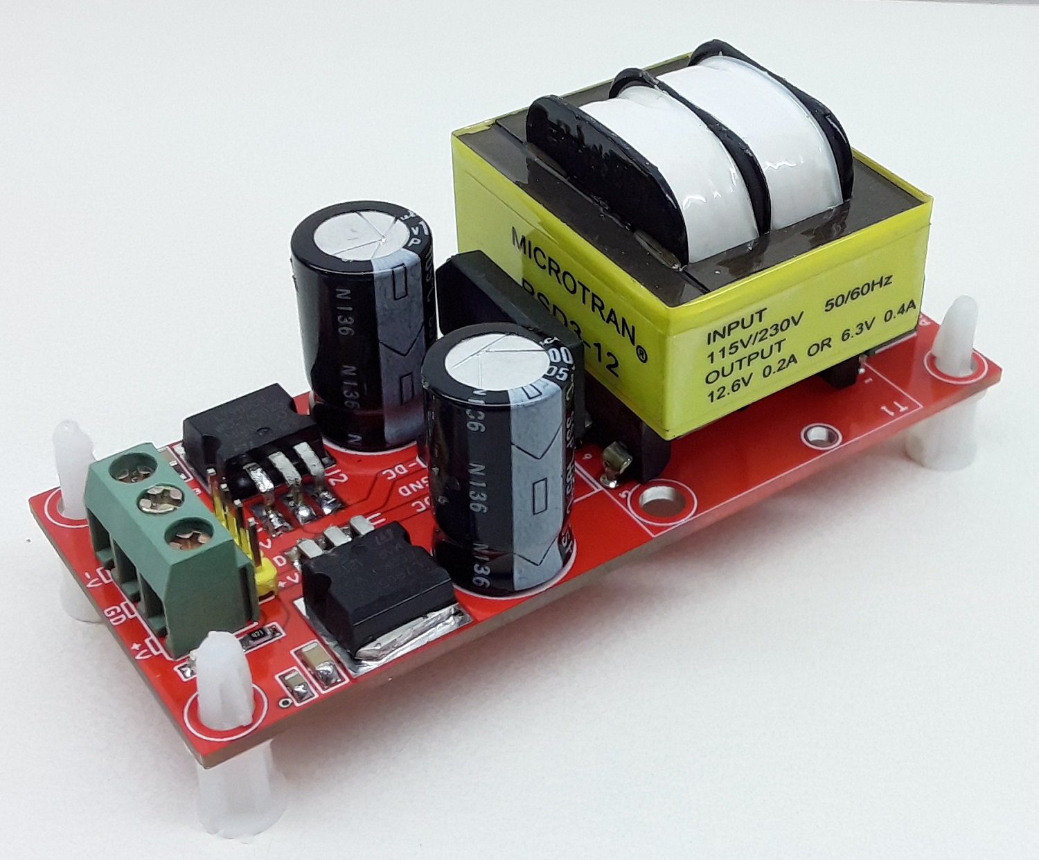
U1 +5V regulator
U2 -5V regulator
D1 +5 power LED
D2 -5V power LED
R1/R2 current limiting resistors for LEDs
C1/C3/C5/C6 output DC capacitors
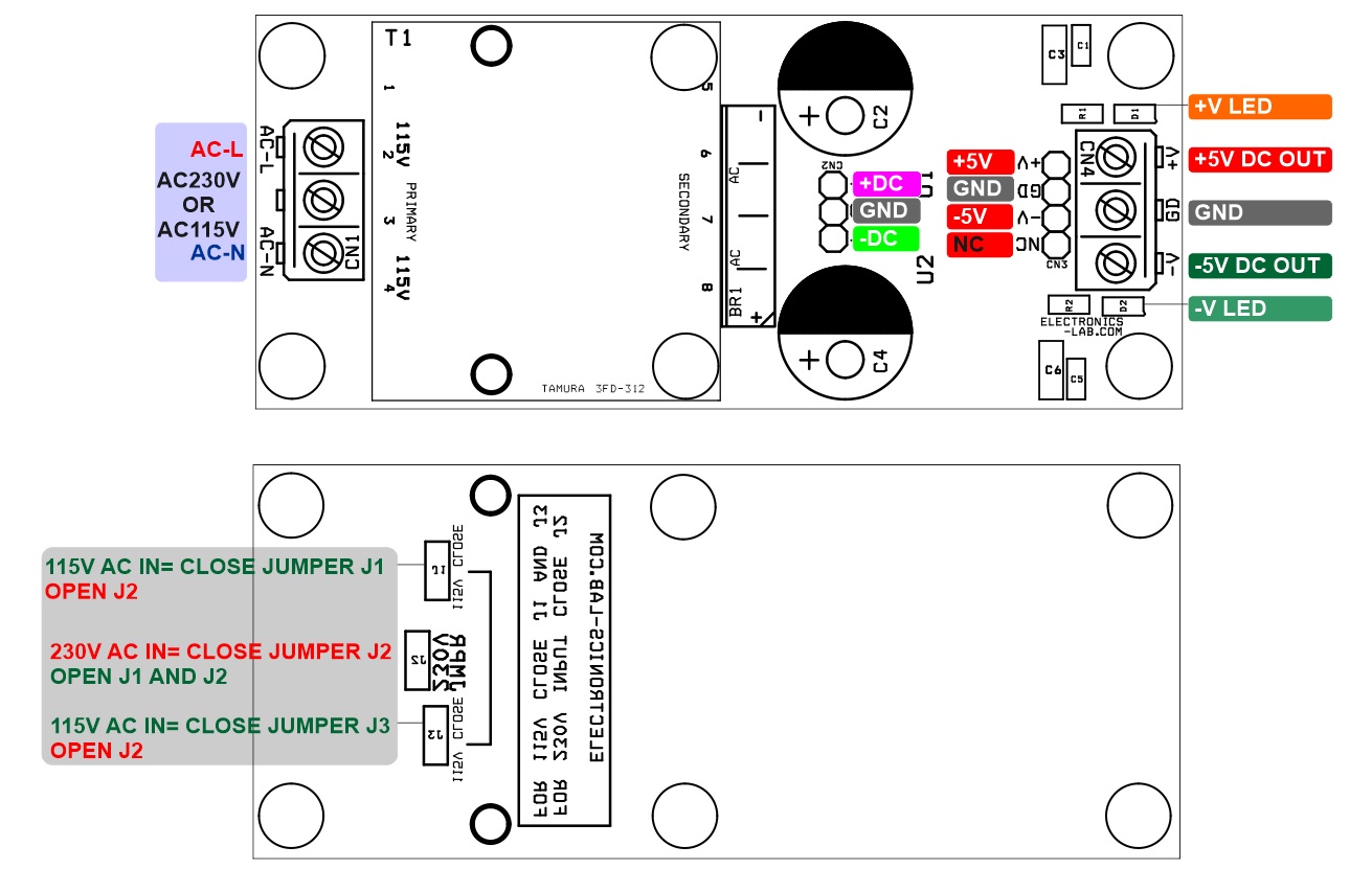
CN3 Male header +/-5V regulated output
CN4 screw terminal +/-5V regulated output
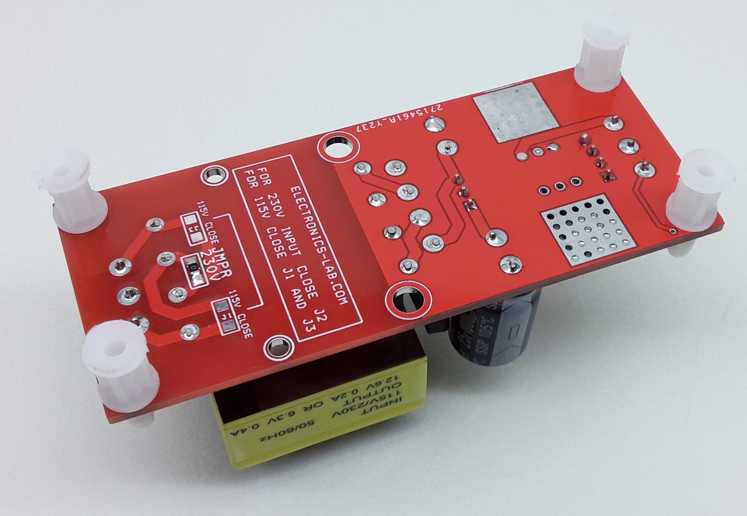
Note1: Power supply supports 230V AC input and 115V AC input. Jumpers are located under PCB for input voltage selection, remove input power cable while changing Jumper selection.
Note 2: This power supply contains hazardous voltage at the input side, PCB must be installed in an encloser that prevents accidental contact. Use plastic screws to mount this power supply PCB.
Input Voltage Selection
For 230V AC Input: Close Jumper J2 and Jumper J1, and Open J3
For 115V AC Input: Close Jumper J1 and J3, Open Jumper J2
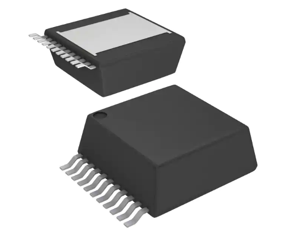
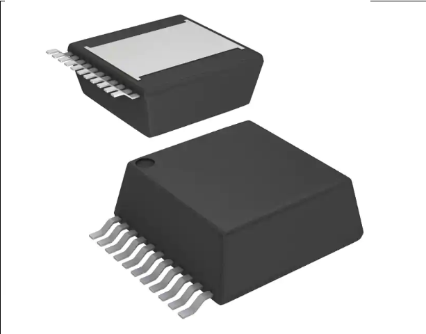
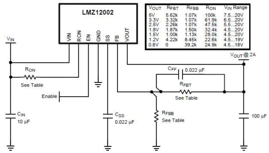
Texas Instruments LMZ120xx SIMPLE SWITCHER® Power Modules provide easy-to-use step-down DC-DC solutions with exceptional power conversion efficiency, output voltage accuracy, line and load regulation. LMZ12001 / LMZ12002 / LMZ12003 SIMPLE SWITCHER® Power Modules can accept an input voltage rail between 4.5V and 20V and deliver an adjustable, highly accurate output voltage as low are 0.8V. These TI power modules have either 1A (LMZ12001), 2A (LMZ12002), or 3A (LMZ12003) output current and offer efficiency of up to 92%. The LMZ12001, LMZ12002, and LMZ12003 have a -40 to +125°C junction temperature range and provide fast transient response for FPGAs and ASICs. These TI devices are ideal for use in point of load conversions from 5V and 12V input rail, time critical, space-constrained high thermal requirement, and negative output voltage applications.
Features:
Integrated shielded inductor
Simple PCB layout
Fixed switching frequency (350kHz)
Flexible startup sequencing using external soft-start, tracking and precision enable
Protection against inrush currents and faults such as input UVLO and output short circuit
Single exposed pad and standard pinout for easy mounting and manufacturing
Fully enabled for WEBENCH® Power Designer
High efficiency reduces system heat generation
Low radiated emissions (EMI) complies with EN55022
Only 7 external components
Low output voltage ripple
No external heat sink required
Specifications
Applications:ITE (Commercial)
Current – Output (Max):8A
Efficiency:92%
Features:UVLO
Mounting Type:Surface Mount
Number of Outputs:1
Operating Temperature:-40°C ~ 125°C
Package / Case:TO-PMOD-11, Power Module
Size / Dimension:0.59″ L x 0.59″ W x 0.23″ H (15.0mm x 15.0mm x 5.9mm)
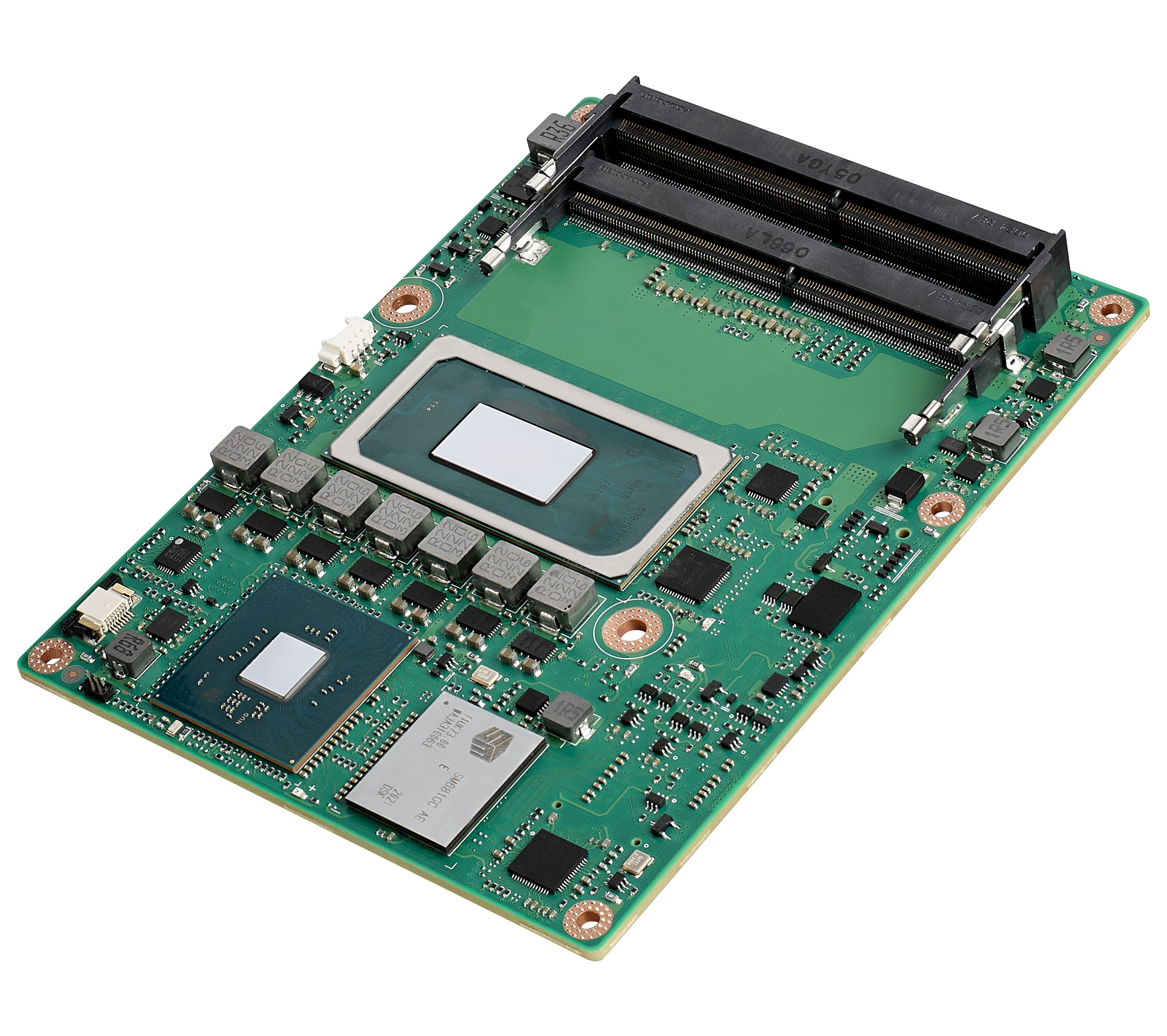
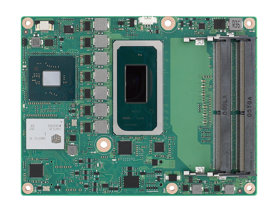
Advantech, a leading embedded and AIoT solutions provider, has released the new SOM-5883 Computer-on-Module for high-performance edge computing applications. SOM-5883 is a COM Express Basic Type6 Module, with integrated 11th Gen. Intel® Core™ processors (formally called Tiger Lake-H). It offers octa-core computing performance under TDP 45Watt, with excellent Intel Iris Xe graphics and ready-to-use Edge AI Suite software toolkit, making SOM-5883 an ideal solution for medical imaging and AI applications.
To resolve the heavy workload of image processing applications, SOM-5883 is designed to support up to 128GB DDR4 3200 SODIMM, with high capacity and high-frequency memory technology paired with ground-breaking computing and graphics performance. In addition, there are numerous super speed I/O interface including PCIe Gen4(16GT/s) and USB3.2 Gen2(10Gbps), 2.5Gbase-T for enhanced system expansion. With optional NVMe SSD and TPM2.0 onboard design, -40~85oC operating temperature and 8.5~20V power input, SOM-5883 is more reliable and delivers greater security for edge computing requirements.
Breakthrough Performance: Octa-Core 11thGen. Intel Processors and QFCS
Equipped with 11th Gen. Intel Processors, SOM-5883 is the first COM Express Type6 module that supports up to 8 Core processors and 128GB DDR4 memory. The SOM-5883 offers a 1.7X computing performance growth and 1.5X 3D graphics upgrade. Advantech provides Edge AI Suite containing Intel Open VINO and more than a hundred AI models to help customers quickly find the right SKU of target AI performance. SOM-5883 has four independent displays up to 4K over three DisplayPort 1.4/HDMI 2.1, optional eDP or LVDS, and VGAl, and it is configurable up to two ports 8K HDR outputs.
Moreover, this product boasts excellent power efficiency ensuring outstanding computing performance while keeping the same 45-Watt CPU TDP as former generations, making it an ideal update on existing systems. With Advantech’s unique QFCS (Quadra flow cooling system) thermal technology, SOM-5883 can release 100% CPU power and deliver optimal performance. The thermal solution design is not only efficient in heat dissipation but also thin, quiet and light, so customers can easily integrate into a 1U height slim chassis.
Next Gen. I/O Interface: x16 PCIe Gen4, 2.5GbE with TSN, and USB4
SOM-5883 is the first COM Express Type6 module offering x16 PCIe gen4, while its bandwidth is double to 16GT/s allowing 31.5GB/s throughput via 16 PCIe lanes. With this, graphics-driven applications such as ultrasound can achieve much more accurate diagnosis by the combination of native graphics engine and external expansion for system configuration. At the same time, SOM-5883 supports multiple cutting-edge I/O technologies. It enables super speed data transmission with improved bandwidth of 2.5G LAN and an NVMe SSD onboard, with the capability to transfer huge data between AIoT applications. The 2.5G LAN equipped with TSN (Time Sensitive Networking) is the ideal choice for automation or edge applications requiring low-latency. This technology fulfills the demand of real-time traffic, prioritising critical data in the communication process, such as transferring command, actions or safety information on time. It also supplies extraordinary USB4, which can be configured as DisplayPort, Thunderbolt, USB 3.2, and USB 2.0 in a slim USB-Type-C connector. Advantech also offers USB4 reference design documents and SOM-MZ10 development board, to help its partners accelerate the implementation of new I/O technology.
Key Features
COM Express R3.0 Basic Type 6 Module
11th Gen. Intel® Xeon, and Core™ i7/i5/i3/Celeron™ Processors
Up to 128GB DDR4 3200MT/s with ECC support
Four independent displays with 3x DDI, eDP/LVDS or VGA.
1 PCIe x16 Gen 4, 8 PCIe Gen 3, 4 USB 3.2 Gen 2, 2.5G LAN w/TSN, 2 SATA3 Ports
Supports Advantech iManager, Edge-AI Suite and WISE-DeviceOn
Operating Temp: Standard: 0 ~ 60 °C (32 ~ 140 °F), Extended: -40 ~ 85 °C (-40 ~ 185 °F)
Reliable Design and Easy Management for Edge Computing
As well as its excellent performance, the new SOM-5883 boasts an optimized design to adapt to diverse applications. It features ECC memory for the error correct function, TPM2.0 chip onboard to prevent cyber-threats, 8.5-20V wide range power input, and -40o~85oC wide operating temperature; the NVMe SSD soldered down design makes it more robust and resistant to vibration when operating in harsh environments, especially in edge computing applications. Beyond the hardware, SOM-5883 also supports BIOS storage protection, security boot, BIOS power-management, plus WISE-DeviceOn for remote hardware monitoring and OTA (over-the-air) software update to prevent system malfunction.
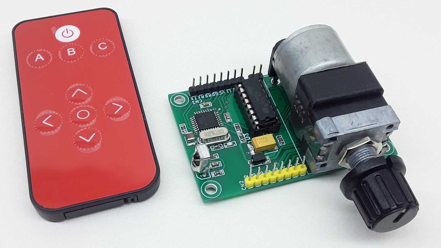
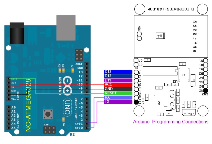
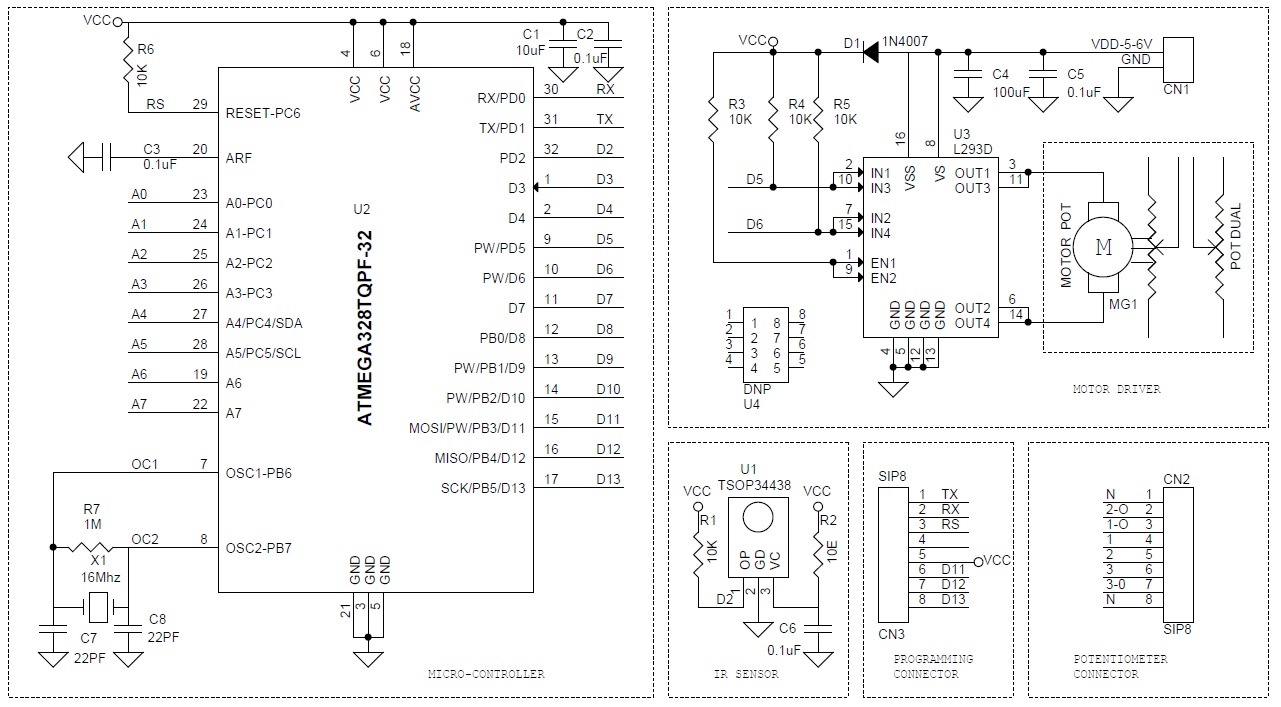
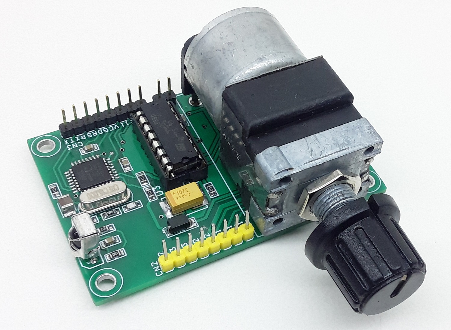
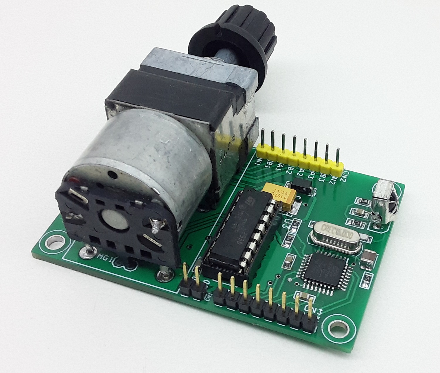
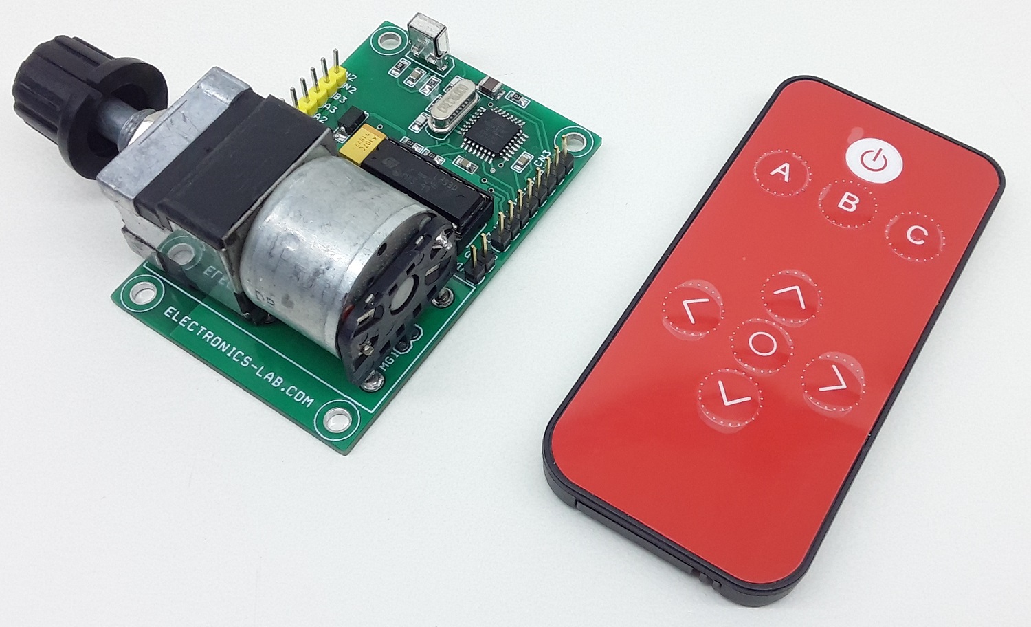
This is an Infrared Remote controlled motorized potentiometer controller. It’s an open-source project built on the Arduino platform and compatible with Arduino IDE for custom programming. The project consists ATMEGA328 microcontroller, IR sensor, L293D motor driver, ALPS Motorized potentiometer, a connector for Arduino programming, etc. The L293D H-bridge drives the potentiometer motor, 2 Parallel direction pins are used to change the motor direction which moves the POT in a forward or reverse direction.
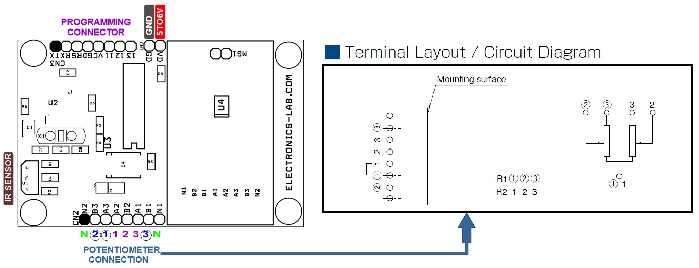
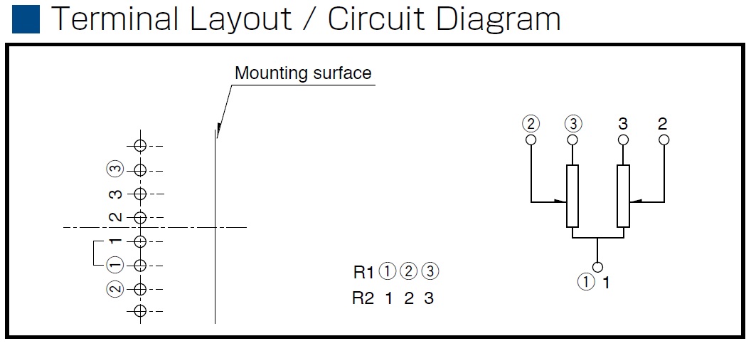
Note: Motorized Potentiometers are built with a highly reliable linear potentiometer, with a slip clutch, geartrain, and motor in a single panel mount assembly which can be manually adjusted.
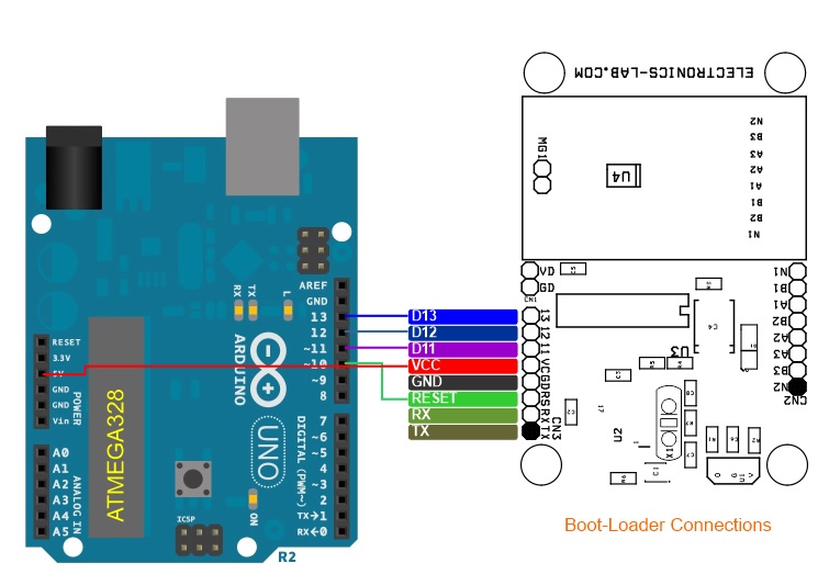
Arduino Pins
Digital Pin D2 >> IR Sensor,
Digital Pin D5 >>Motor Direction IN1+IN3,
Digital Pin D6 >> Motor Direction IN2+IN4
Components
U1 IR Sensor
U2 ATMEGA328 Micro-controller
U3 Motor Driver
CN3 Programming Connector
CN2 Potentiometer Connection
CN1 Power Input 5 To 6V
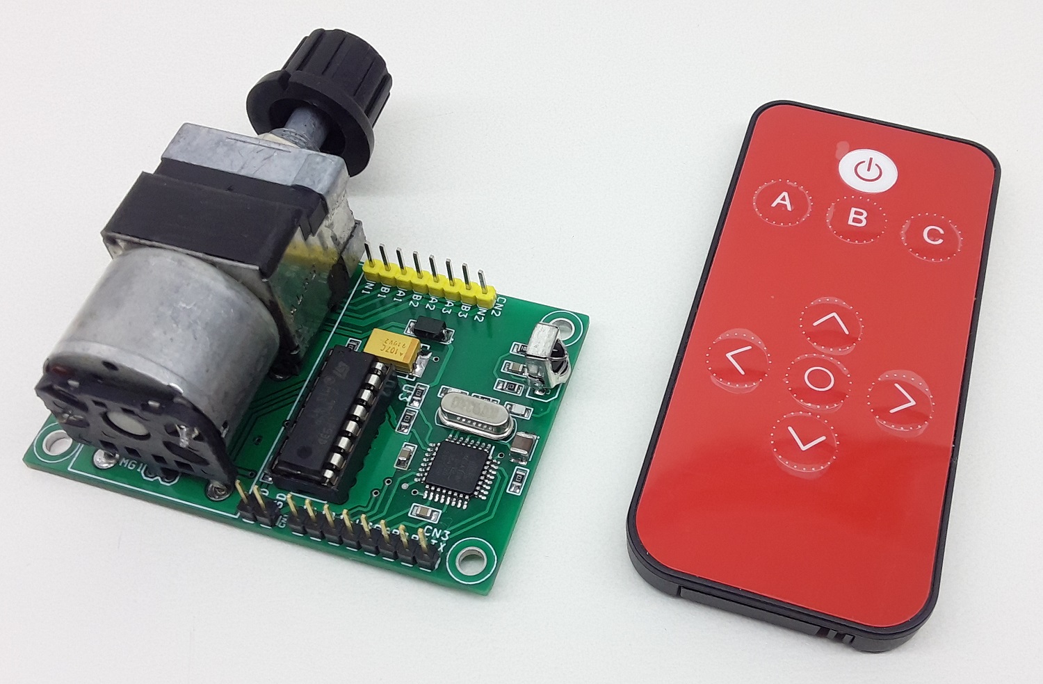
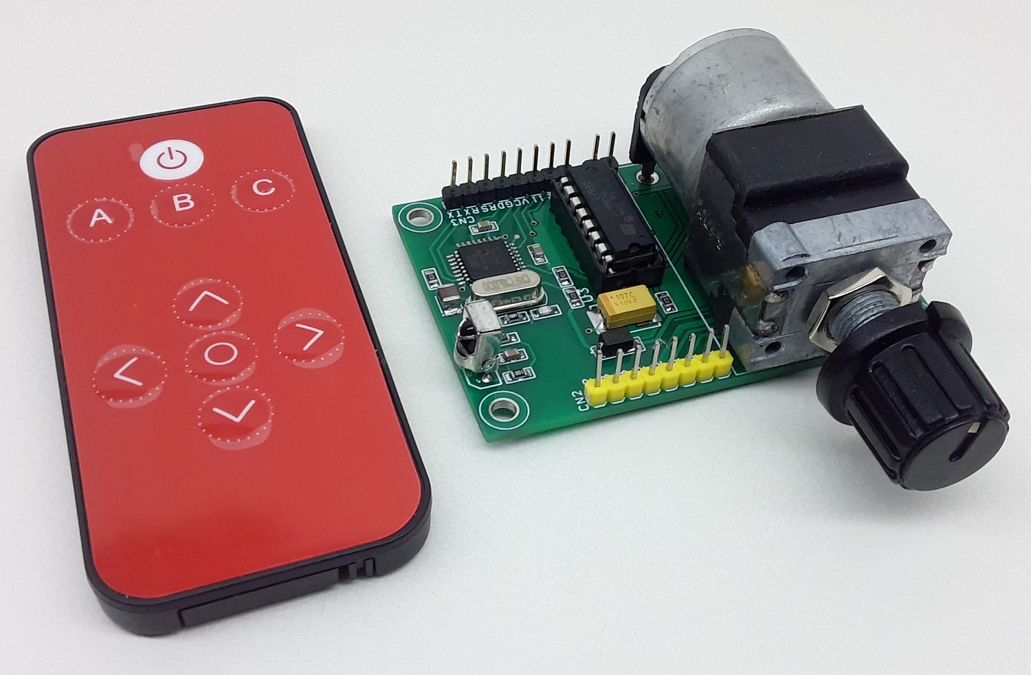
Arduino Code and IR Remote
Arduino Code is available as a download below
Switch A and Switch C of IR Remote Controls Motor Direction.
User May modify this code as per requirement
The project is compatible with Spark fun IR Remote COM-1489.
Any IR Remote with 38Khz frequency will work with this project
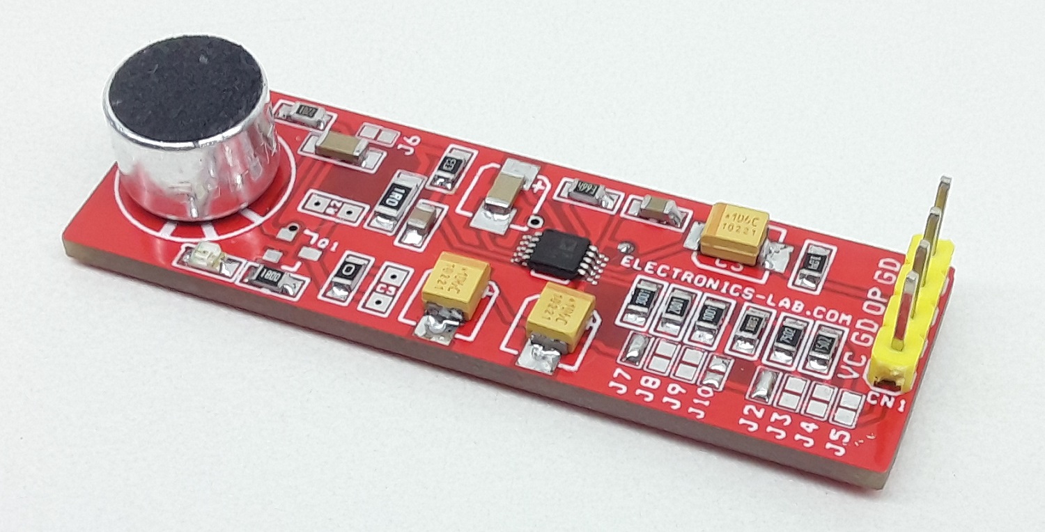
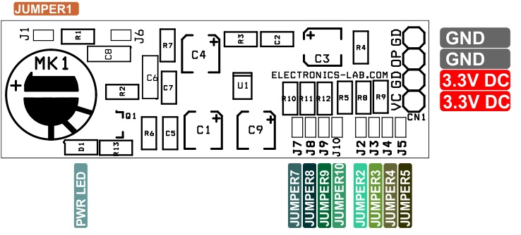
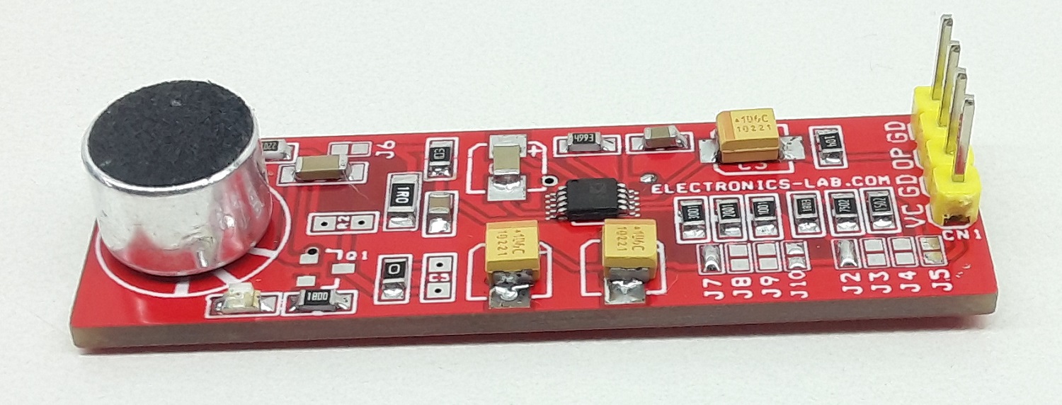
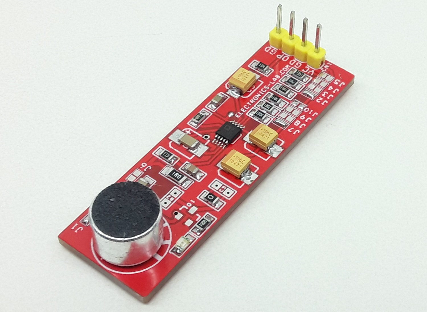
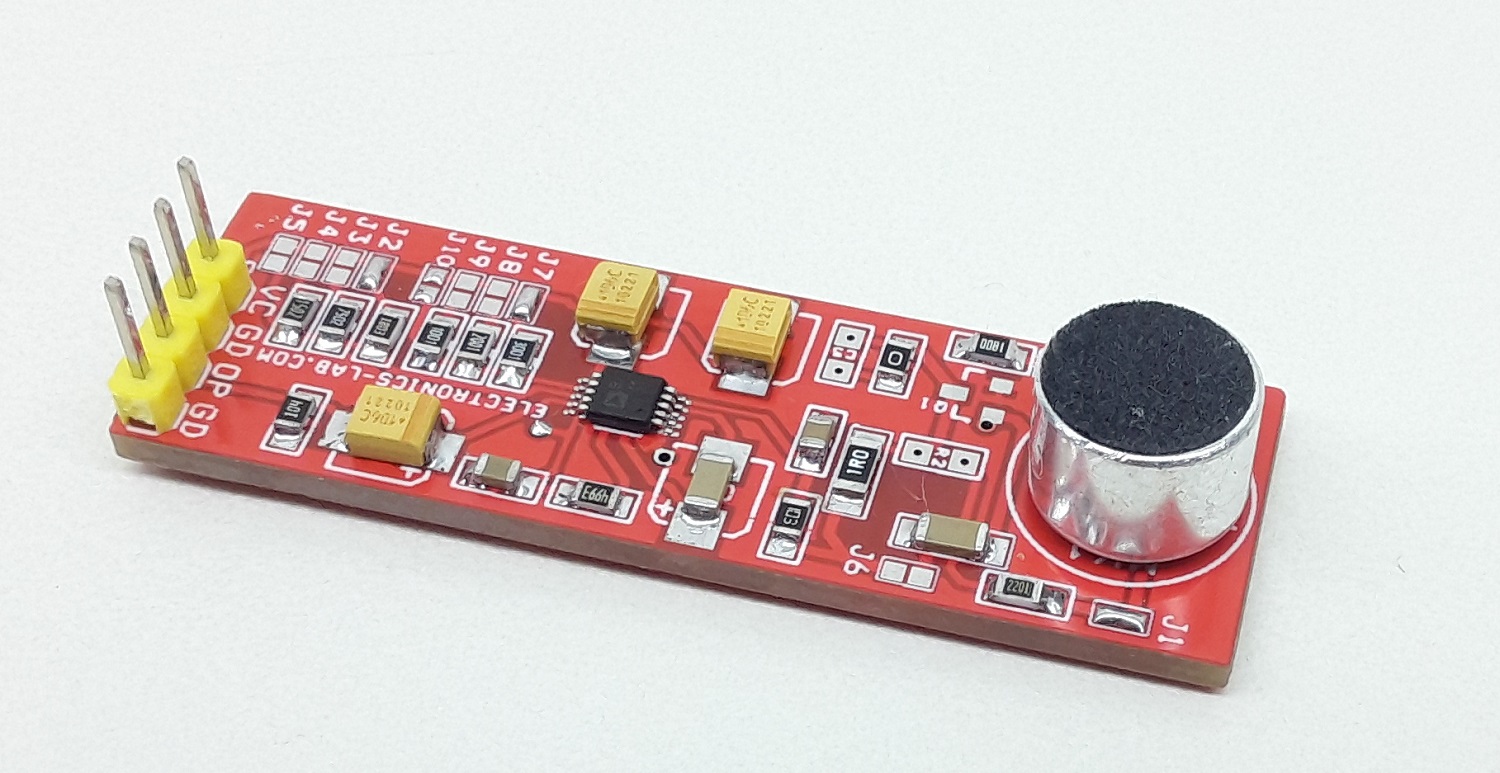
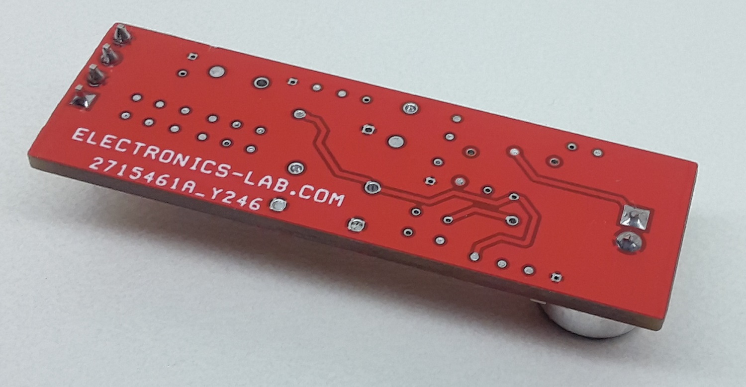
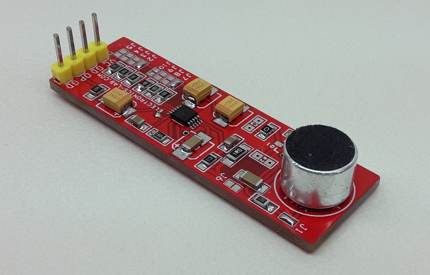
This is a complete microphone signal conditioning project. Designed primarily for voice-band applications, this project provides amplification, limiting, variable compression, and noise gate. User-adjustable compression ratio, noise gate threshold, and two different fixed gains optimize circuit operation for a variety of applications.
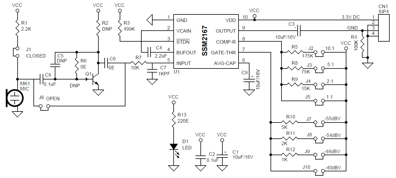
This is a complete and flexible solution for conditioning condenser microphones for personal electronics and computer audio systems. It is also excellent for improving vocal clarity in communications and the public address systems. A low noise voltage-controlled amplifier (VCA) provides a gain that is dynamically adjusted by a control loop to maintain a set compressions characteristic. The compression ratio is set by a jumper and can be varied from 1:1 to over 10:1 relative to the fixed rotation point. Signals above the rotation point are limited to prevent overload and eliminate popping.
A downward expander (noise gate) prevents the amplification of background noise or hum. This results in an optimized signal level prior to digitization, thereby eliminating the need for additional gain or attenuation in the digital domain. The flexibility of setting the compression ratio and the time constant of the level detector, coupled with two values of rotation point, make the SSM2167 easy to integrate into a wide variety of microphone conditioning applications.
Compression Ratio
This project provides four different settings for the compression ratio in the same manner as the noise gate threshold. Experiment with different compression ratios to determine what sounds best in a given system, starting with 2:1 is recommended. A high compression ratio exaggerates the effect of the noise gate because the compression ratio determines the gain at the noise gate. Compression of 10:1 only in systems where the noise floor is well below the noise gate. Most systems require between 2:1 and 5:1 compression for best results. The compression ratio keeps the output steady over a range of source to microphone distances.
Note 1: Do not install Q1, R2, C5, they are optional components, can be used when very low input signal is applied.
Electret Microphone or Dynamic Microphone (Project Supports Electret Microphone and Dynamic Microphone)
Open Jumper J1 and Electret Microphone to Connect Dynamic Microphone or self-power microphone.
Close Jumper J1 for Electret Microphone
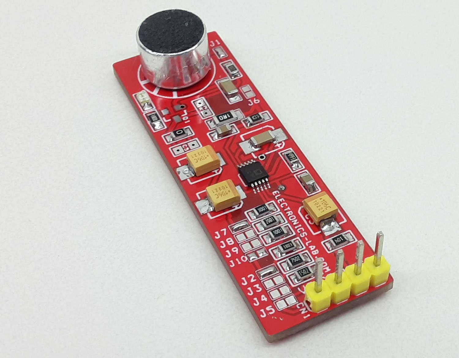
Setting The Compression Ratio (PCB Solder Jumper) Jumper J2 Compression Ration 10:1
Jumper J2 Compression Ration 10:1
Jumper J3 Compression Ration 5:1
Jumper J4 Compression Ration 2:1
Jumper J5 Compression Ration 1:1
Setting The Noise Gate Threshold (PCB Solder Jumper) Noise gate keeps the background sounds subdued.
Jumper J7 Noise Gate (dBV) -55
Jumper J8 Noise Gate (dBV) -54
Jumper J9 Noise Gate (dBV) -48
Jumper J10 Noise Gate (dBV) -40
Features
Operating Supply 3.3V DC
On Board Condenser Microphone
On Board Power LED
Jumpers to Set Various Noise Gate (J7, J8, J9, J10)
Jumpers to Set Various Compression Ratio (J2, J3, J4, J5)
Jumper J1 for Biasing Voltage to Microphone, Open if Biasing Supply not Required
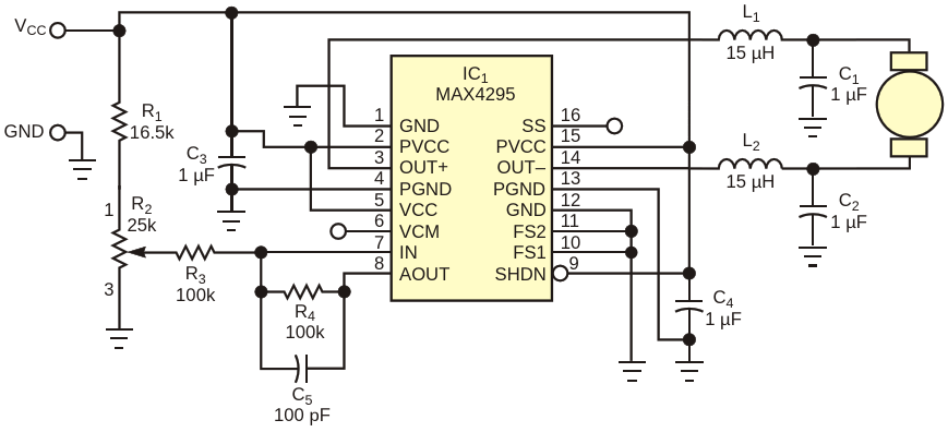
Class D audio amplifiers provide a dual benefit for battery-powered portable devices (Figure 1). They enhance battery life, and they produce much less power dissipation than do their linear cousins. Those features make Class D amplifiers ideal candidates for controlling speed and direction in small electric motors.
The standard application circuit for a Class D audio amplifier, IC1, requires only slight modifications. In place of the usual audio-signal input is a variable dc voltage that potentiometer R2 generates. Resistor R1 biases the potentiometer to match the input range of IC1. Full-counterclockwise rotation of the potentiometer corresponds to maximum-speed reverse rotation of the motor. Midscale on the potentiometer corresponds to motor off, and full-clockwise rotation of the potentiometer produces maximum-speed forward rotation in the motor. The characteristics of a given motor may allow you to eliminate the amplifier’s output filter, which comprises L1, L2, C1, and C2. But, unless the control circuitry is near the motor, you should include the filter to reduce EMI.