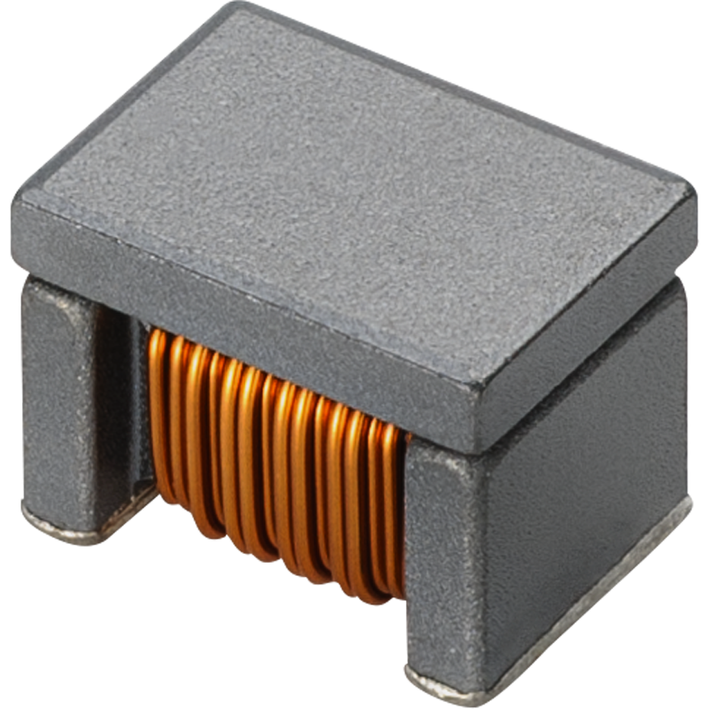
Measuring 1812 inch, Murata’s new broadband inductors for Bias-T circuits provide high inductance of 22 μH and high current of 700 mA in vehicle-mounted PoC used in SerDes interfaces. These new inductors use Murata’s original ceramic materials and coil structures to offer high performance.
The new LQW43FT_0H series ensures high-impedance performance over a broad range in the low frequency band from several MHz to 100 MHz. The product can be used in combination with existing Murata products LQW32FT 0H Series (1210 inch size) and LQW21FT 0H Series (0805 inch size) to reduce the number of parts and mounting space required for PoC. This can help to reduce the size and weight of devices installed in vehicle-mounted cameras.
Key Features of LQW43FT_0H Series Inductors
Small-Size: 1812 inch size inductor for Bias-T circuits that provides both a high inductance of 22 μH and a high current of 700 mA.
Ideal for use as inductors for vehicle-mounted PoC used in SerDes interfaces.
Product lineup supports a wide inductance range (10 μH to 22 μH).
The mass production of LQW43FT_0H series is scheduled to begin in September 2021.
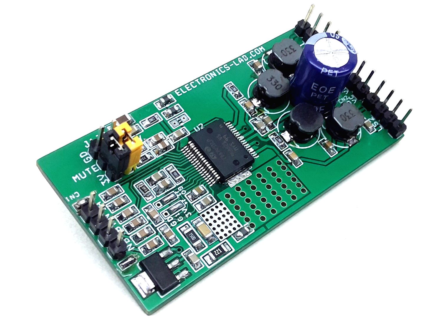
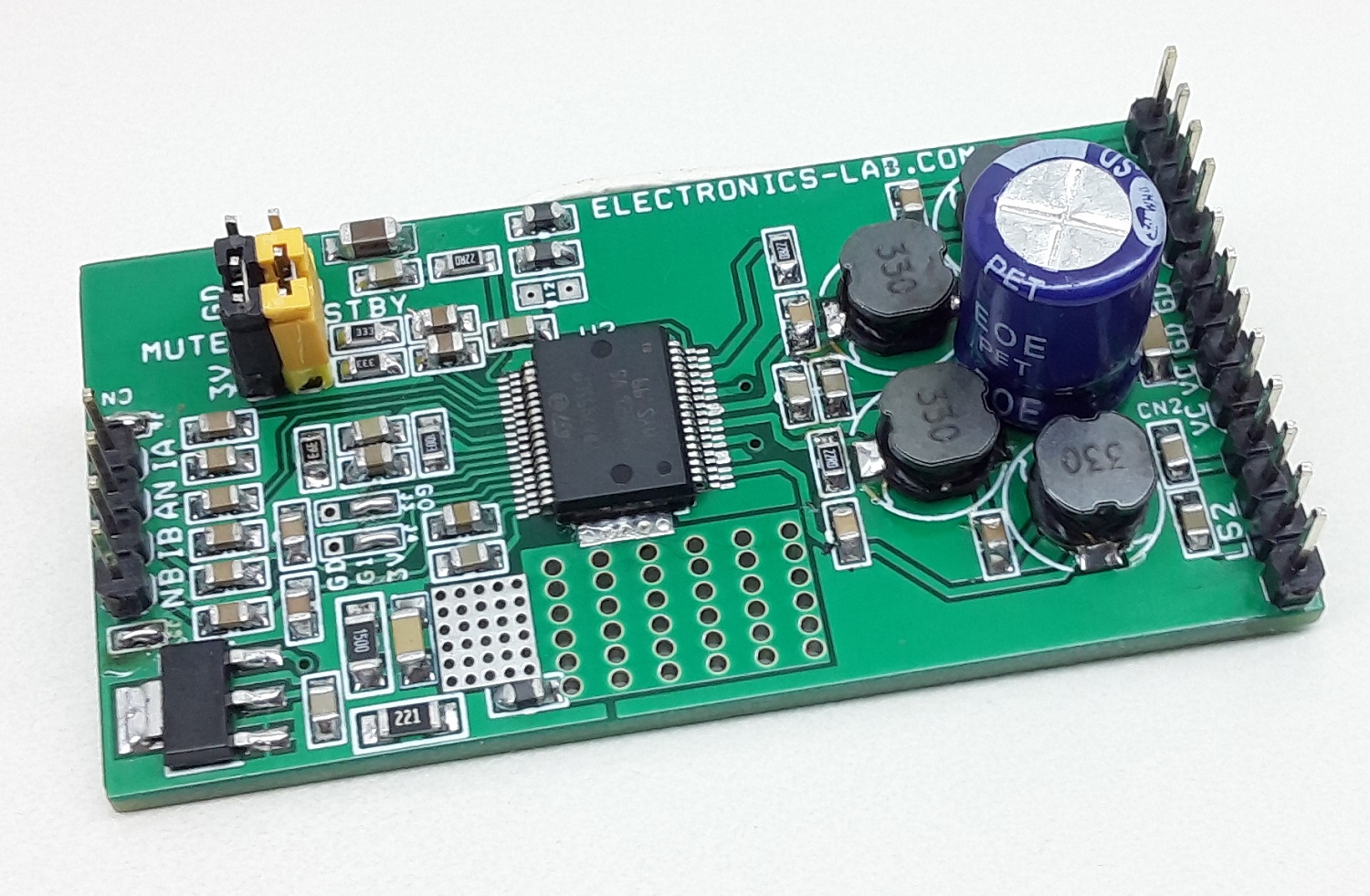
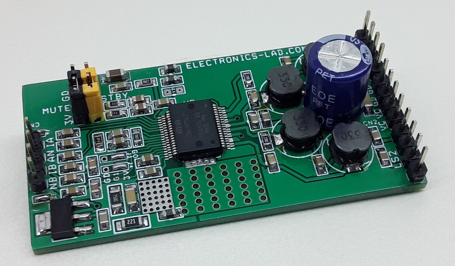
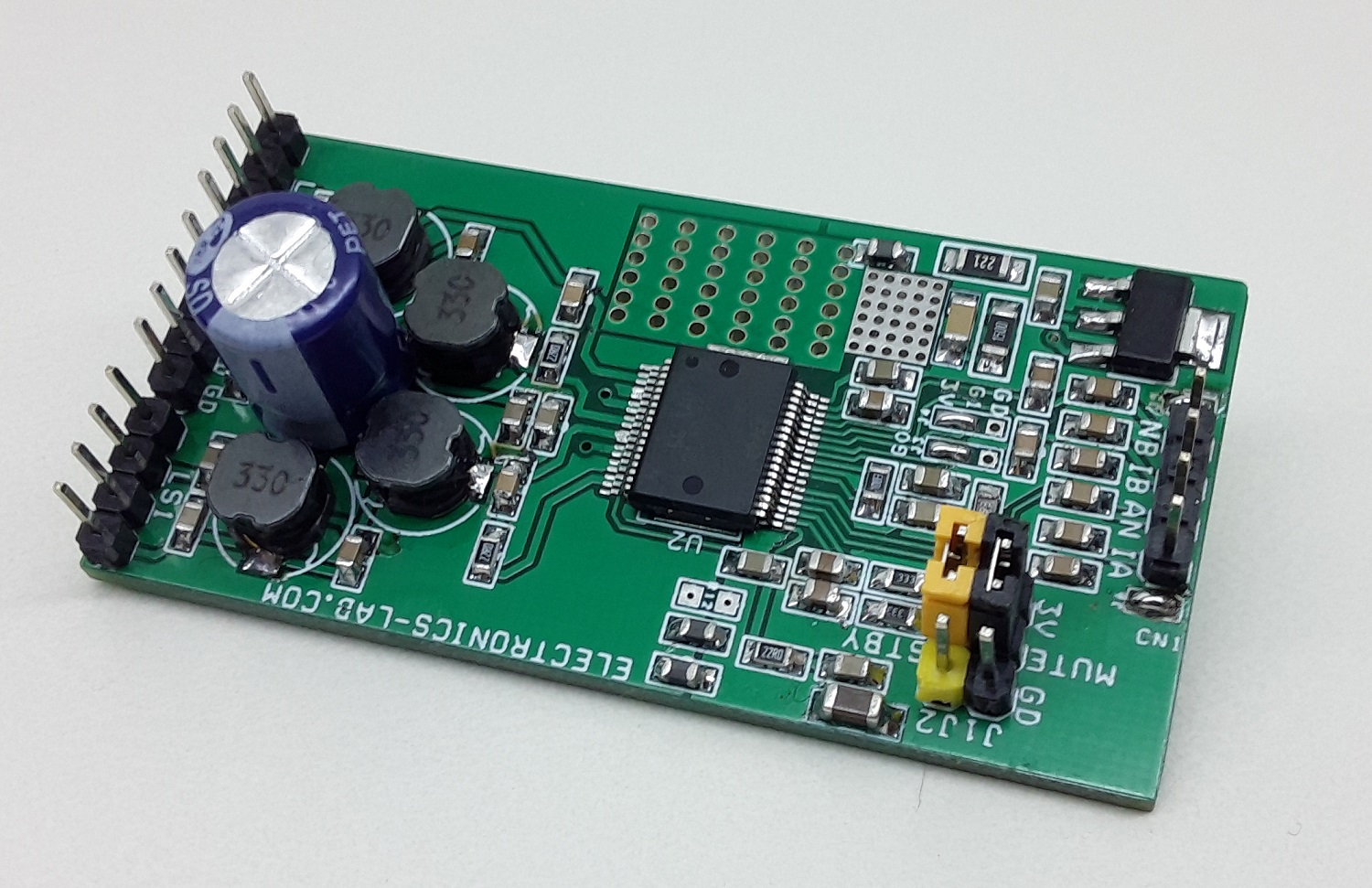
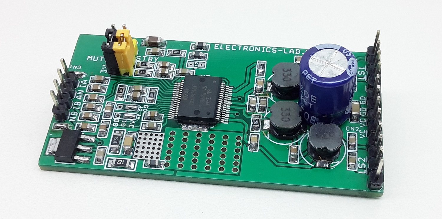
The project described here is a high-efficiency dual BTL class-D audio amplifier with single supply operations. The project was built using TDA7491LP13TR from ST. The low profile PCB design can fit in a small area, operating power supply 9-12V DC, Project supports single-ended or differential audio signal inputs. Jumpers are provided to set the various gains, standby, and mute functions.
5 W + 5 W Dual BTL Class-D Audio Amplifier – [Link]
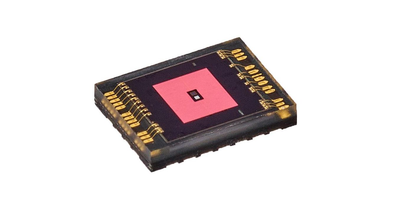
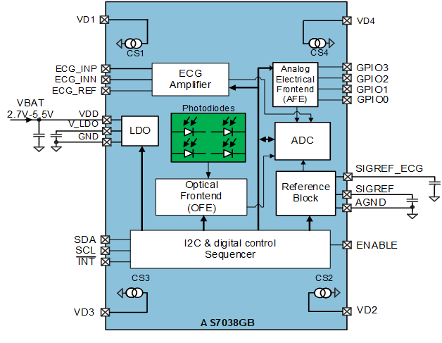
ams’ biosensor solution is based on photoplethysmography and electrocardiogram
The operation of the ams AS7038RB is based on photoplethysmography (PPG) and electrocardiogram (ECG). PPG is the most used HRM method, which measures pulse rate by sampling light modulated by the blood vessels, which expand and contract as blood pulses through them. PPG is also used to measure blood oxygen saturation (SpO2). ECG is the reference for any measurement of the biopotential generated by the heart. Embedded ECG analog front end satisfies IEC 60601-2-47 requirements.
The solution includes LED drivers, photo-sensor, analog front-end (AFE), sequencer, and application software. In addition, the device also enables skin temperature and skin resistivity measurements by providing interfaces to external sensors.
Compare to ams’ previous generation, AS7038RB has a 250% larger photodiode with lower LEDs driving current to achieve the high PPG performances. The AS7038RB’s low-power design and small form factor are particularly well suited to application in earbuds, fitness bands, smartwatches, sports watches, and smart patches in which board space is limited and in which users look for extended, multi-day intervals between battery recharges. The thin package dimension makes the AS7038RB suitable for height constrained solution likes earbuds or smart patches. The photodiode filter centered on red and infrared wavelengths and embedded ADC make the AS7038RB suitable for disposable pulse oximeter solutions.
Features
Address all skin types
Allows smallest application size, e.g., narrow HRM measurement band
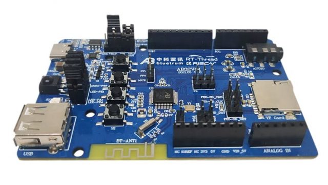
Bluetrum, a Chinese chip manufacturer known for its high-performance Bluetooth speakers and headsets, has designed an audio player microcontroller for audio applications and other general purposes. The new device named AB32VG1 is an Arduino Uno – like development board with a high-performance 32-bit core that relies on IP based on the RISC-V instruction set created by Bluetrum. The Bluetrum Bluetooth AB5301A RISC-V MCU is said to have a frequency of 120 MHz and is overclockable up to 192 MHz.
The AB32VG1 development board is a great competition for ARM-based development boards, no doubt. It comes with a USB port, a microSD card slot, and various GPIO headers that make interfacing with other devices possible. It is quite small in size but it has all the necessary feature that makes developing with it easy.
Here are some of its features and specifications:
High-performance 32-bit RISC-V MCU that can be clocked up to 120 MHz and overclockable up to 192 MHz
192KB RAM
1MB flash memory of 1MB flash
MicroSD card slot
Wireless communication through Bluetooth 5.0 and Bluetooth Low Energy (BLE).
Onboard PCB antenna designed for FM radio applications
Power: 5V via USB Type-C or Vin pin on the expansion header
Audio
3.5mm audio jack
Audio code with 16 bit stereo DAC and 2-channel 16 bit ADC
4-channel stereo analog MUX
2-channel MIC amplifier input
Stereo audio ADC with 90dB SNR
Stereo audio DAC with 95dB SNR
Support for flexible audio EQ adjust
Temperature:
Operating Temperature: -40 °C to +85°C
Storage Temperature: -65°C to +150°C
Dimensions: 9 cm x 6 cm
Operating System
The AB32VG1 development board also runs on the popular RT Thread, an open-source embedded real-time operating system that is used for several applications. The OS comes in two versions: the standard version (consists of a kernel layer, components and service layer, and IoT framework layer) and the nano version (which has a very small footprint and refined hard real-time kernel). It can be programmed using the RT-Thread Studio IDE, and there are several tutorials online that can help with this, in case you are interested.
Bluetrum’s AB32VG1 is currently available and can be purchased from Tabao for 79.90 Yuan, approximately $12. Other useful details on the board including the datasheet and schematic can also be found on their official product page.
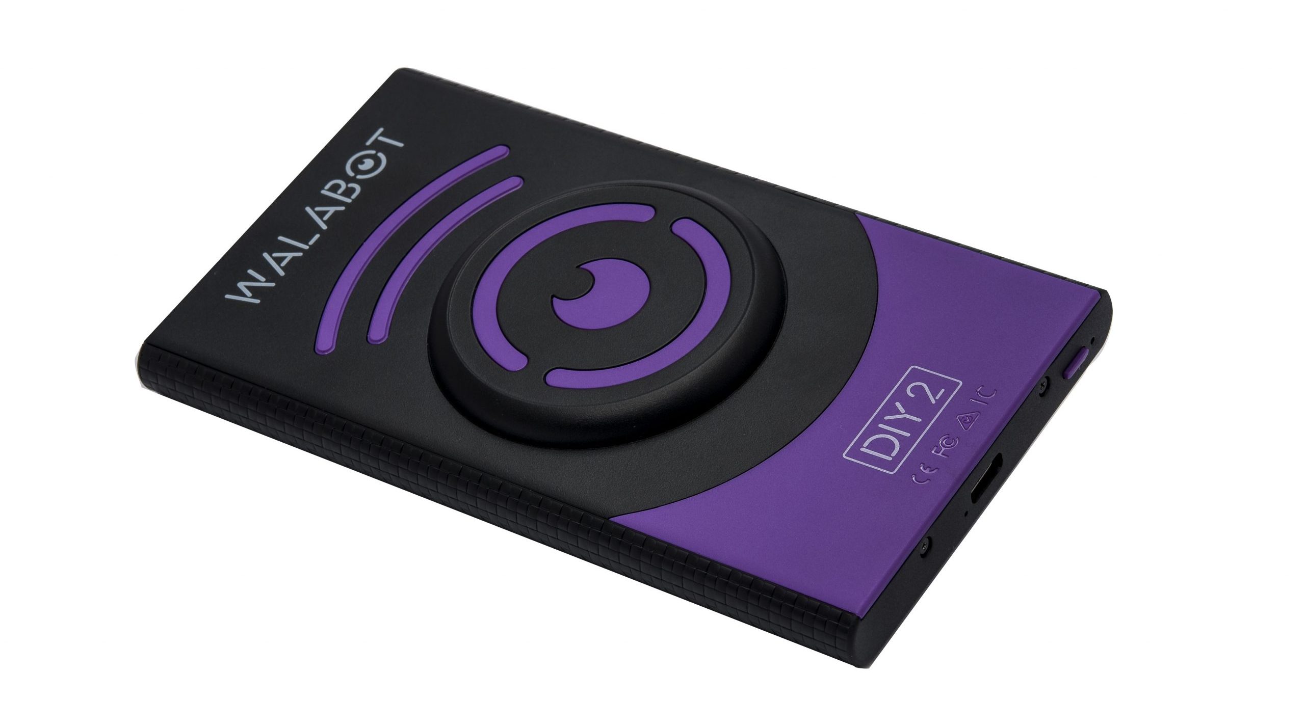
4D Imaging has always been a significant functionality from the perspective of B2B products. Also, the usage of microwave and radio technology highlights the complexity and necessity of such features in a product. But Vayyar Imaging has developed a Visual Stud Finder product specifically for domestic DIYers and hardware enthusiasts. Thus launching the Walabot DIY 2 featuring the 4D Imaging technology for the consumer market.
Walabot DIY 2 is the succeeding version of the previous Walabot products by Vayyar Imaging. The series of Walabot products are wall scanners for finding studs using 4D radio-frequency for imaging. The Walabot DIY 2 comes with Wi-Fi functionality, thus enhancing the device’s connectivity and overpowering the previous versions of Walabot.
Vayyar’s Walabot Products
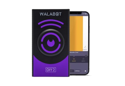
The older versions of Walabot only supported the Android OS, which limited the product’s reach. But Walabot DIY 2 is compatible with iOS and Android, thus increasing the consumer base to Apple users as well. The ideology behind the iOS support might be to capture the US mobile markets, as 60% of the market is constituted by Apple users.
Demand for devices like Walabot DIY2 has further increased due to the ongoing pandemic as household activities are restricted to the in-house members. So, using DIY products for carrying out necessary activities seems like the most viable alternative. Additionally, it gives you the flexibility to use it any time you require without waiting for an external professional to complete the job.
Zeev Lissack, Head of Walabot DIY said “We’ve received tens of thousands of requests from iPhone users. We are thrilled to deliver Walabot DIY 2 which is loaded with our most advanced and intuitive wall scanning technology and features. Most other stud finders use audio beeps or LEDs, which can be confusing for users, creating a fear of drilling. Our mission is to allow everyone to look before they drill and renovate with confidence.”
Walabot connects with your phone and offers a user-friendly interface for finding the dead center of every stud in the target area. It ensures that the internal wirings and pipes inside the wall are not affected by any external activity. Hence, the device’s essential utility acts as a see-through scanner for any solid surface or object. It also avoids any additional expense caused due to the destruction of vital components on the target surface or object.
Demo Video of Walabot DIY 2
Talking about depth sensing, Vayyar’s sensors have always been exclusive in terms of imaging and sensing as safety applications are one of their major target systems. Hence, sensing technology using the 4D radio frequency is very much reliable for many applications and use cases. So, Walabot DIY 2 using Vayyar’s 4D Imaging technology can measure up to 4 inches or 10 cm deep inside the surface.
Walabot DIY 2 is available at $167.92 in the Walabot store. For more information, you can visit the official product page and the press release.
Efficient routing applications require effective bandwidth management, reduced network management cost, flexible function selection, friendly management interface with a fast boot time amongst other features which are usually tedious with hard routers. This is why a Shenzhen, China-based hardware manufacturer, Seeed, recently launched a new mini router based on the Raspberry Pi CM4 for soft routing applications to meet these demands.
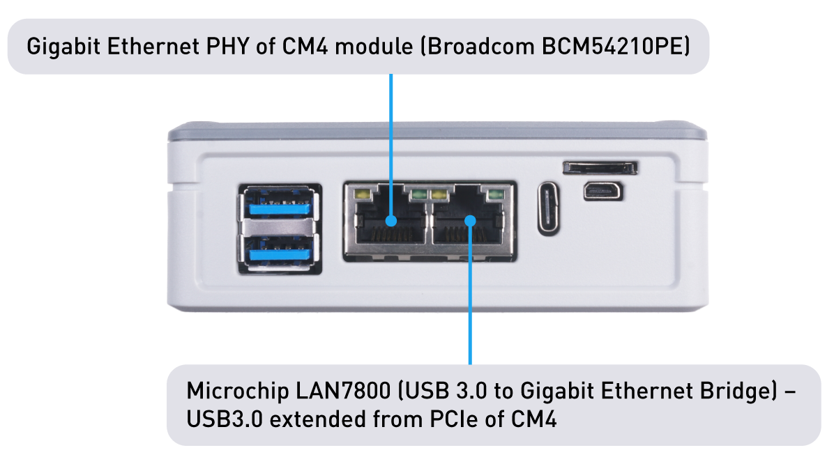
The Carrier board is wired with 4GB RAM and 32GB eMMc for a fast boot-up time and an enhanced user system experience. The board offers flexibility to users as its pre-installed CM4 is replaceable with any other CM4. The dual Gigabit Ethernet ports (RJ45) can support system processing speed up to 1Gbps. With one port connected to the Gigabit Ethernet PHY of the CM4 Broadcom BCM54210PE base module, the other Gigabit Ethernet port is connected to LAN7800 of microchip, a USB 3.0 to Gigabit Ethernet bridge (Gbe). The USB 3.0 interface is the extension from the PCIe interface of the CM4 module.
The Dual Gigabit Carrier board is a perfect standard for Raspberry Pi Users, designers, and developers – HTPC makers, software router enthusiasts, Linux developers, and others alike.
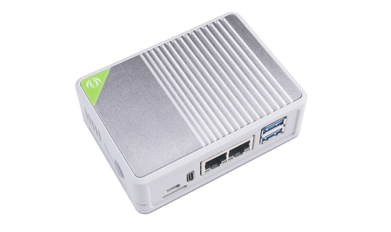
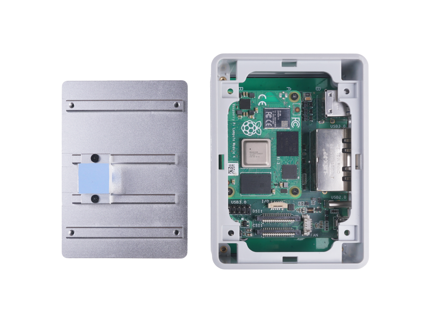
It is suitable for industrial applications as it is packed in a PC/ABS case with a large aluminum alloy sink on top to cool down the CM4 at extreme temperatures arising from heavy loading. This fabrication provides it with better protection.
Key features and specifications include:
Powered by Raspberry Pi Compute Module 4
4GB RAM/ 32GB eMMC
Dual Gigabit Ethernet connectors
Pre-installed OpenWrt firmware
MIPI CSI, MIPI DSI, and micro-HDMI interfaces
2x USB 3.0 with 1x USB 3.0 9-pin header
1x MicroSD Card slot
More Expandability via FPC Connector
1x Fan power connector
Power via USB Type-C
Aluminum alloy top with large heat sink
PC/ABS case with better protection. Case has long rubber feet for better stability
Keyhole slot wall mount
DIN rail mount support with mounting holes
Dimensions: 75mm x 64mm x 21mm
Additionally, the Compute Module 4 comes with OpenWrt firmware pre-installed out – of – the – box. This makes it easy to fix it to the existing home network by simply unboxing the package and making the right connections with the board. OpenWrt is an open-source Linux operating system compatible with and executable on embedded devices such as routers with enhanced functionalities, performance, and even security in contrast to ordinary routers. It has a package management system that supports the flexibility to suit User’s applications and a writable filesystem.
Input/Output Peripherals
The board has MIPI CSI, MIPI DSI, Micro -HDMI to connect displays (cameras), a standard 9 – pin USB 3.0 header for more USB expansion. It also has a micro-SD slot to load system images for non – eMMc versions of CM4 and an FPC connector for more expandability as input and output peripherals.
Applications
The Dual Gigabit Carrier Board offers infinite possibilities to a variety of applications in software router, IoT, smart home, and camera projects.
Mounting/Deployment
The case can be either mounted using a keyhole slot on its rear to hang it to the wall or using the 3 mounting holes provided on its back to fix it to a DIN rail. The device’s casing is furnished with long rubber feet to ensure stability when fixed to a flat surface.
Further Details
More useful information on both the carrier board and Compute Module can be found on the Product page on Seeedstudio
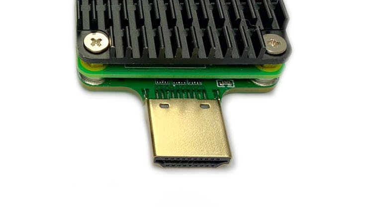
Recent times have shown that an increased number of portable home entertainment streaming technologies with non – region specific circuitry have made access to TV shows, movies, and games easier and more exciting. With HDMI port and high computing performance of one of such devices like the much-celebrated Raspberry Pi 4B, direct connection to a monitor or TV is now a matter of seconds, and this has made the Raspberry Pi 4 range of boards one of the most sought after for several applications involving a television. However, having a slightly high form factor is still an issue with these boards as it is not too easy to hide them behind a TV. To address this problem, MBS decided to create a new system on chip (SoC) carrier board that turns a Raspberry Pi Compute Module 4 into a TV Stick.
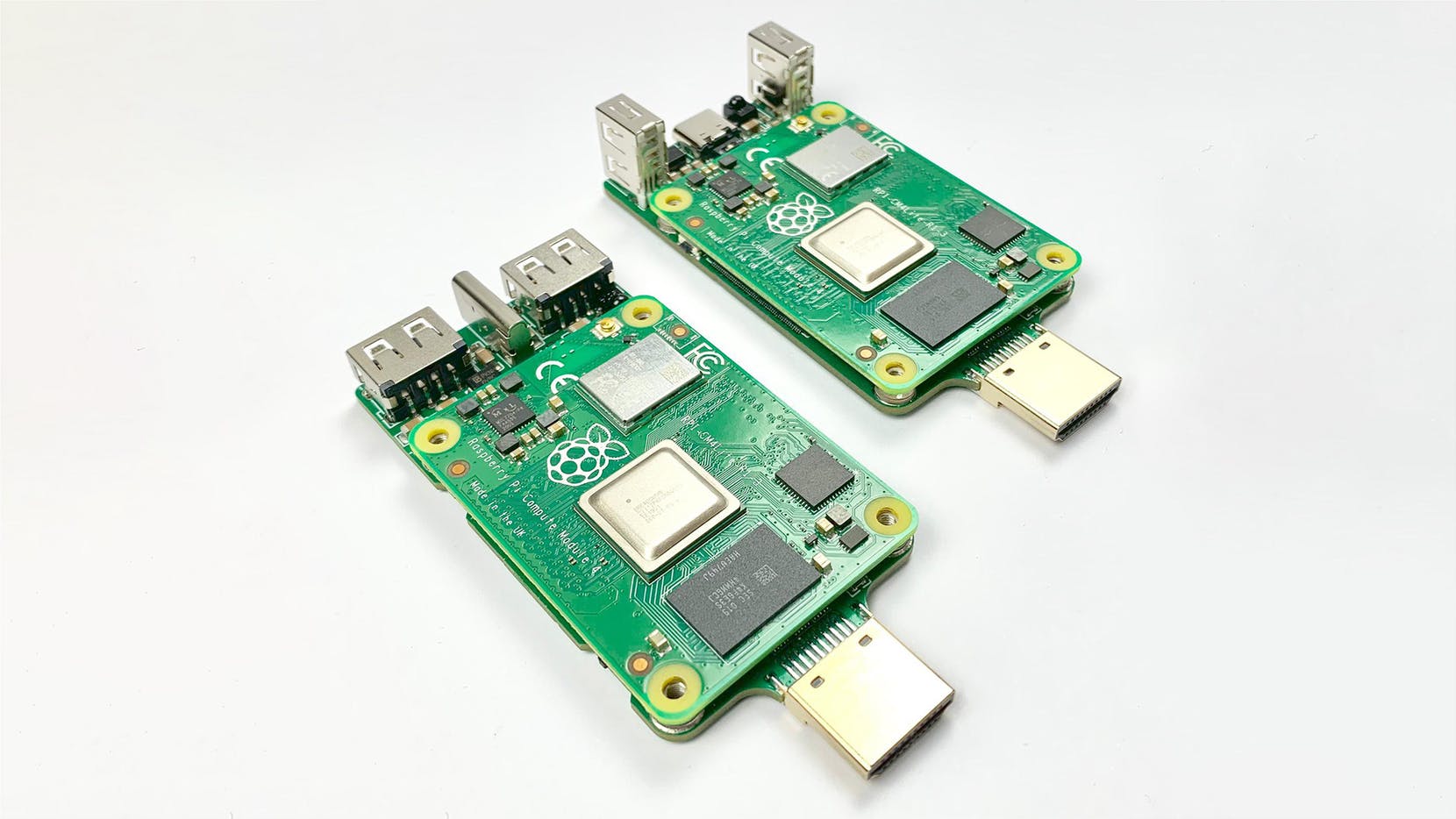
The Raspberry Pi CM4 TV Stick allows users to connect to a TV/monitor directly with an HDMI plug while powered via a USB-C connector. Despite its small size, the CM4 TV Stick features high-density connectors that allow you to attach them to application-specific carrier boards. The carrier board also has a user button that acts as a boot select for eMMC flashing, and a micro-SD card connector that allows the chipset to load system images for non-eMMC versions of CM4 as well. In addition to the super light, flexible, and movie features that should make the TV stick endearing to users, it also offers more entertainment allowing users to turn their monitor or TV into a smart TV with Kodi applications, and a gaming console for retro games with retropie.
Features and Specifications include:
High-compatibility with Raspberry Pi CM4 eMMC
No-eMMC
1x HDMI plug
1x microSD card connector
USB multiplexer selector switch that enables two USB-A ports or CM4 USB device mode
1x USB-C connector
2x USB 2.0 USB-A connectors
1x IR receiver
1x user button
Power and Act LEDs
14x GPIOs, with GND, 5V and 3.3V solder pads
Slim Heatsink with fasteners
Weight: 46g
Size: Has a really small form factor that makes it easily transportable without the need for an HDMI extender.
MBS has made a successful test of the carrier’s radio communication with control while its receiver is behind a TV and facing the wall. Thanks to its IR receiver. The board has also been tested with eMMC CM4 for flashing and MBS is also considering adding pins for Ambilight setup to its board.
The board is currently in the testing, modification, and standardization stage of its production and will be available for sales in September for $35.
The project described here is a high-efficiency dual BTL class-D audio amplifier with single supply operations. The project was built using TDA7491LP13TR from ST. The low profile PCB design can fit in a small area, operating power supply 9-12V DC, Project supports single-ended or differential audio signal inputs. Jumpers are provided to set the various gains, standby, and mute functions.
Key Features
5W + 5W Continuous Output Power, 10% THD, (8 Ohms Speaker) at 9V DC
Single Supply Operation 9V to 12V
Four Selectable Fixed Gains Settings of nominally 20dB, 26dB, 30dB, 32dB Using Jumpers
Differential Inputs Minimize Common-Mode Noise
Jumper for Single-Ended Inputs
No “Pop” Sound at Turn-On/Off
Thermal Over Load Protection
Standby and Mute Features Using Jumpers
PCB Dimensions 63.25 x 32.39 mm
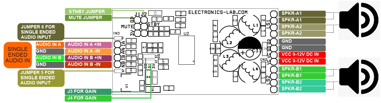
Mode Selection
There are three operating modes defined bellow:
Standby mode: all circuits are turned off, very low current consumption
Mute mode: inputs are connected to the ground and the positive and negative PWM outputs are at 50% duty cycle.
Play mode: the amplifiers are active
Jumper Setting Standby, Mute and Play Mod (Low=GND, High=3.3V)
Standby Mode: Jumper J2 =Low, Jumper J1 (Don’t Care Whether low or high)
Mute Mode: Jumper J2=High, Jumper J1 Low
Play Mode: Jumper J2 = High, Jumper J1 High
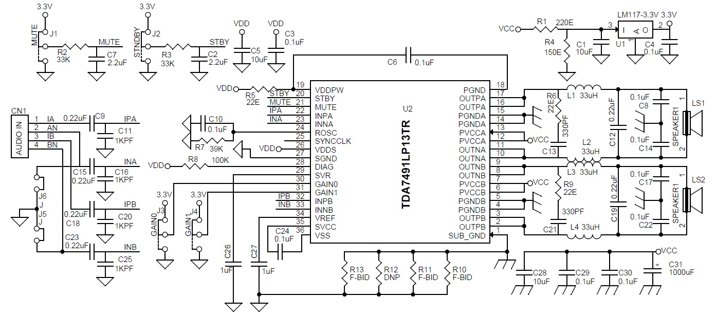
Audio Signal Input (Single-Ended or Differential) Differential audio signal can be feed directly to CN1 , PIN 1 to 4
Pin 1 >> IA +Input A Channel, Pin 2>> AN -Input A Channel
Pin 3 >> NB +Input B Channel, Pin 4>> BN -Input B Channel
For Single Ended Input Solder Jumper J5 and J6 (Channel A Input Pin1 Signal and Pin 2 GND, Channel B Pin3 Signal and Pin 4 GND)
Gain Setting (PCB Solder Jumper J3 and J4)
The gain of the TDA7491LP is set by the two inputs, GAIN0 (pin 30) and GAIN1 (pin 31). Internally, the gain is set by changing the feedback resistors of the amplifier.
The Exclusive-OR gate gives an output given by the expression “A or B not Both”. It means that the output of the Exclusive-OR gate is low when both inputs “A” and “B” are at the same logic level i.e. both “HIGH” or “LOW”. In the case of, either “A” or “B” that is “01” or “10” the output of the Exclusive-OR gate will be “HIGH”.
The Exclusive-OR is also referred to by writing only Ex-OR or XOR. The Ex-OR is a very useful logic and is mostly used in arithmetic, error detection, and computational circuits.
The logic Ex-OR is constructed using basic logic gates which are AND, OR, and NOT gates. Although using these basic logics many functions/ logics can be constructed but the importance of Ex-OR logic has led it to be constructed as a separate logic gate. Because of its construction from multiple basic logic gates, it is also called a “hybrid” logic gate. The logic OR gate, which was discussed in the previous article, is an inclusive-OR function which states to include both “A” and “B” states in logic “HIGH” output. Whereas, as mentioned earlier in this article, the Ex-OR logic excludes states of both “A” and “B” inputs from the logic “HIGH” output. Because of the inclusion and exclusion of both input states, the logic OR is termed as inclusive-OR and Exclusive-OR, respectively. In simple words, the output of Ex-OR logic goes “HIGH” only when both inputs are different.
The Boolean algebraic equation is given below:
Logic Ex-OR Gate Symbol & Truth Tables
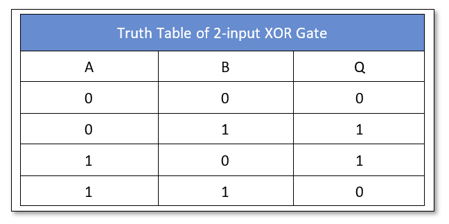
The representation of an Ex-OR logic by a symbol is shown in the following figure. Basically, a two-input Ex-OR logic is a modulo two-adder as it gives the sum of two binary numbers.
Figure 1: Logic Ex-OR Gate Symbol
The truth table of a two-input Ex-OR logic is shown below:
It is clear from the truth table that when inputs are at different levels i.e. either “01” or “10” then the Ex-OR logic output is “HIGH” and in case the inputs are at the same level then output is “LOW”. In other words, “A” or “B”, not both!.
The Boolean equation of Ex-OR logic is:
The expression for an inclusive-OR logic consists of a plus symbol between the operands and denotes a logical addition/summation of the inputs. Whereas, the expression of Exclusive-OR logic comprises a plus sign within a circle between the operands. The circle basically describes a direct sum of sub-objects.
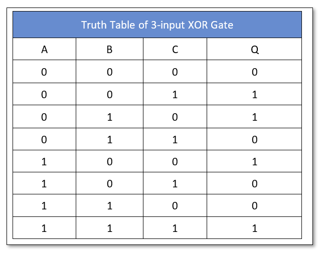
The logic function performed by a more than two-input Ex-OR gate is basically a modulo 2 sum and is not an Ex-OR logic. The truth table of a three-input Ex-OR logic is as follow and can be expanded to include any number of inputs:
For three input Ex-OR logic, when there is an odd number of inputs with logic “HIGH” then the output is “HIGH” and this characteristic makes the Ex-OR an odd gate. Moreover, the ability of Ex-OR to compare logics at the input and to produce results at the output based upon inputs is really useful in arithmetic, error-detection, and computational circuits.
The symbol and expression of a 3-input Ex-OR logic are given below:
Figure 2: Three input Ex-OR Gate Symbol with expression
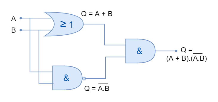
Ex-OR (XOR) Logic Circuit
Using the above equation of a two-input Ex-OR logic, an equivalent circuit can be constructed which is shown in the following figure.
Figure 3: Equivalent Circuit of an Exclusive-OR logic
The above equivalent Ex-OR logic comprises AND, OR, and NAND logics. However, it is not a good practice to include multiple logics for the construction of logic gates and a better Ex-OR circuit can be constructed using only NAND logic gates.
The construction of Ex-OR gate using NAND gates only is shown below:
Figure 4: Equivalent Circuit of an Exclusive-OR logic using NAND Gates
The Exclusive-OR logic gates are helpful in performing arithmetic operations such as addition in the form of Adders and Half-Adders. They have the ability to provide a “carry-bit” or as a controlled inverter to facilitate the addition of larger binary numbers.
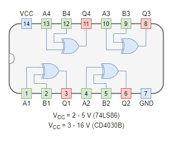
Commercially Available E-OR (XOR) Gates
The XOR logic gates are available in both TTL and CMOS logic families. The most commonly used XOR logic packages are:
In the following figure, an XOR gate is used to drive a 12V relay to switch on the lamp using NI Multisim. The XOR gate (74LS86) turns off the relay when all of the inputs are connected to VCC/ Ground. The relay thus turns off the lamp through an external circuit of 12V. When one of the inputs is connected to VCC, XOR logic goes “ON” turning the relay and lamp to “ON” state.
Figure 6: A Multisim circuit showing XOR logic to control an external circuit
Conclusion
The output of the Ex-OR logic is “LOW” when all of the inputs are in logic “HIGH” or “LOW” states.
The Ex-OR gate outputs logic “HIGH” only when inputs are different (not the same).
The Ex-OR logic is not a basic logic but obtained the status of logic due to its usefulness and versatility.
It is mostly used in arithmetic, computational and error-detecting circuits.
It is also mostly used as a logic comparator because of its ability to compare logical inputs.
It is widely used in Full-Adders and Half-Adders circuits to binary numbers,
The Ex-OR logic gates are commercially available in both TTL and CMOS packages.
An external circuit can be controlled by Ex-OR logic with the use of a magnetic relay.
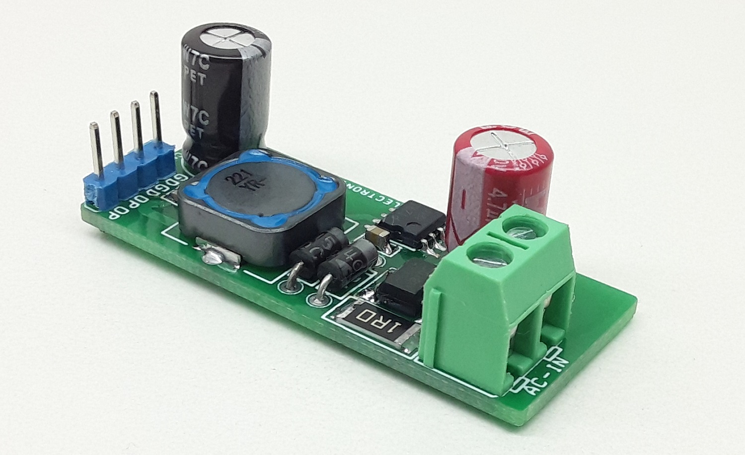
The project described here outputs 12V DC voltage from the input of 230V AC. The output current is up to 100mA. The project is based on BM2P129TF chip which is PWM method DC/DC converter with a built-in 650V MOSFET. BM2P129TF contributes to low power consumption by built-in a 650V starting circuit. Built-in current detection resistor realizes compact power supply design. Current mode control imposes current limitation on every cycle, providing superior performance in bandwidth and transient response. The switching frequency is 100Khz in fixed mode. At light load, frequency is reduced and high efficiency is realized. Built-in frequency hopping function contributes to low EMI. Low on-resistance 9.5 Ohms 650V MOSFET built-in contributes to low power consumption. The default over current limit of the chip is 450mA.
230V AC Input – 12V Output DC Converter, Non-Isolated Buck Converter – [Link]