IBASE Technology Inc., a leading provider industrial computing and innovative digital signage solutions, launches its SI-654-N fanless digital signage player powered by Intel’s latest 11th Gen Core™ U-Series processors (formerly Tiger Lake) manufactured with Intel’s 10nm SuperFin transistor that achieves up to 17.5% performance uplift and significantly higher clock speeds at lower power compared to the original 10nm.
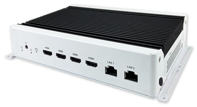
The SI-654-N is currently offered with an Intel® Core™ i7-8665UE processor (8M Cache, up to 4.40 GHz) integrating the high-performance Iris Xe GPU, Intel’s 12-Gen graphics with 96EUs. Measuring 200 x 139 x 41 mm, the compact SI-654-N can be easily installed in space-constraint environments. It houses four HDMI 2.0 connections to deliver up to 1x 8K display or 4x 4K displays, performing a vivid 8K resolution and ensuring a truly immersive audience’s viewing experience.
Mainly designed for digital signage in busy places where there is a constant demand for practical information, the SI-654-N features HDMI-CEC control, display status monitoring, flexible video wall configurations and hardware EDID emulation that prevents distorted or black screen due to display and cable connection issue.
“The new industrial-grade SI-654-N is perfectly suited for video wall solutions in airports, shopping malls and other commercial premises that require reliable 24/7 operation,”
said Archer Chien, director of solution product planning at IBASE.
“With our advanced iSMART and Observer technologies, the SI-654-N is equipped with low temperature boot protection, power resume control, power on/off scheduling, and hardware monitoring to enable continuous and stable operation.”
SI-654-N FEATURES:
iSMART intelligent energy-saving technology – enables power on/off scheduling and power resume functions
11th Gen Intel® Core™ U-series processor (Tiger Lake platform)
1x M.2 E-key (2230) for WiFi or capture card option
TPM 2.0, vPro and watchdog timer
Industrial-grade robust, fanless and compact design
For the deployment of high computing performance signage, the model SI-654 with cooling fan is also available. Both players support TPM 2.0 for optimal cyber security and vPro for easy remote monitoring and management. A webinar to introduce the player will be hosted on August 31th via Digital Signage Today.
Register now to learn more details with the SI-654-N!
Author: Marian Hryntsiv, Documentation Engineer, Dialog Semiconductor
Introduction
There is a variety of applications where a mechanical potentiometer is part of a user control interface. These mechanical potentiometers can be changed to more updated and reliable encoder-controlled elements and digital rheostats, being components that change the electrical parameters of the signal.
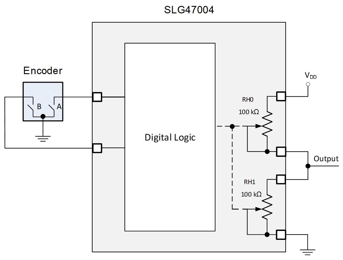
In this article, we used GreenPAK™ SLG47004. It is a great choice for this project as this circuit combines two digital rheostats and configurable logic to process the encoder information. This combination allows the implementation of many designs: a regulated power supply, an amplifier with a tunable gain, and others. In addition, the presence of digital logic allows determining the speed of rotation of the encoder. This approach is shown in Figure 1.
Figure 1: General Schematic of a Voltage Divider Controlled by the Encoder
1. System Overview
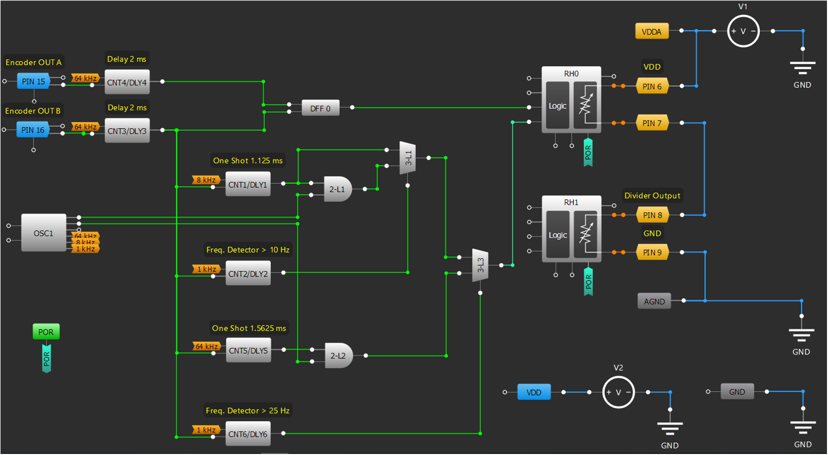
Figure 2 shows the internal circuit design based on the SLG47004.
Figure 2: GreenPAK Designer Project
The complete design file created in free GUI-based software – GreenPAK Designer – can be found here.
An incremental encoder generates its A and B output signals which are used to change digital rheostats resistance. Rheostats form the potentiometer and allow the implementation of the adjustable voltage divider to regulate an output voltage.
At any time, the phase difference between the A and B signals will be positive or negative depending on the encoder’s direction of movement.
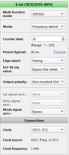
A speed determination function is built from Frequency Detectors, One-Shots, and Multiplexers.
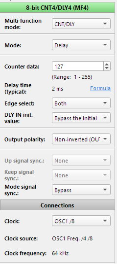
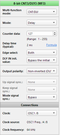
In this article, the EC11 encoder was used. The encoder produces noisy output oscillations due to a switch bounce. To eliminate that noise, 2 mS delays were used. Please note that this delay is adjusted for the EC11 encoder (according to its datasheet). For other encoders, the delay value should be assessed accordingly.
2. Functional Block Architecture
2.2. Digital Logic Description
2.1.1. Determining the Encoder Direction
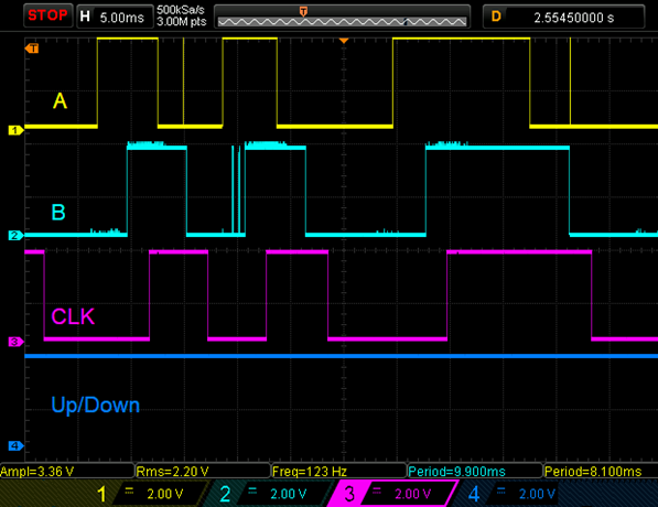
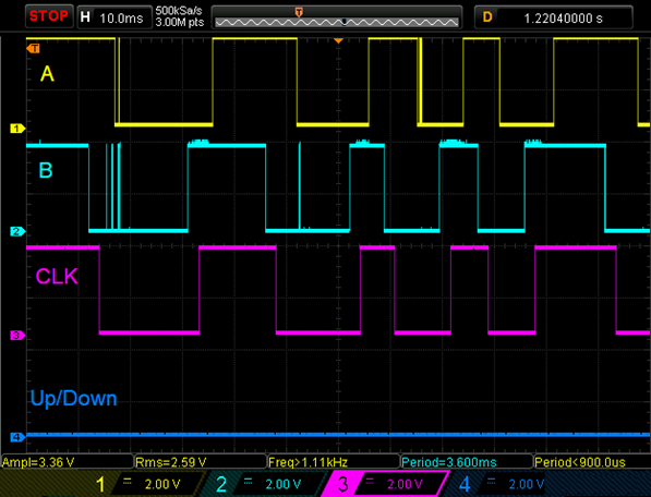
At first, Delay macrocells delay both edges of the encoder output signals for 2 mS. Delay macrocells work like a deglitch filter to eliminate switch bouncing. Delayed signal B appears on DLY inputs of One-Shots and Frequency Detectors, and CLK input of DFF. Delayed signal A appears on the D input of DFF. When the encoder disk is rotating in a clockwise direction signal A leads signal B and DFF output is High, and when the disk is rotating in a counterclockwise direction signal B leads signal A and DFF output is Low. So DFF can determine the direction of rotation. High or Low signal on Rheostat Up/Down input determines if internal counter’s value increases or decreases for each pulse at CLK input.
A timing diagram for the clockwise encoder rotation is shown in Figure 3 and for the counterclockwise encoder rotation in Figure 4.
Figure 3 Timing Diagrams for Clockwise Encoder RotationFigure 4 Timing Diagrams for Counterclockwise Encoder Rotation
2.1.1. Determing the Encoder Speed
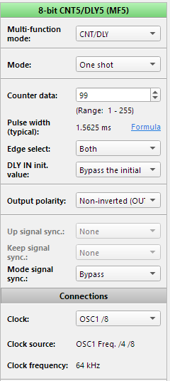
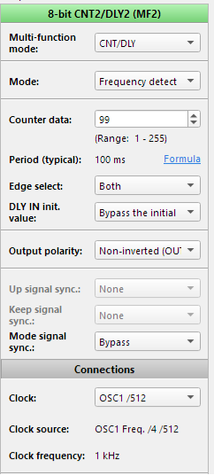
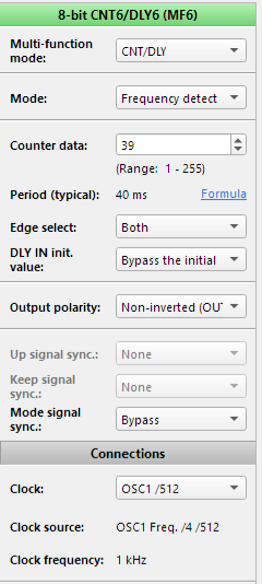
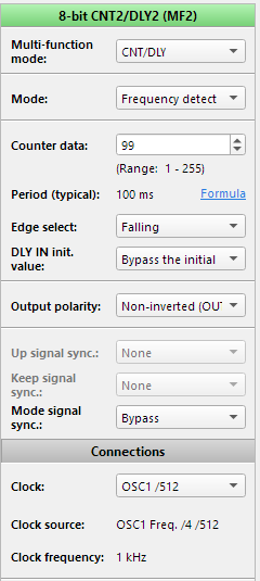
The SLG47004 has 10-bit digital rheostats, which in turn allows the implementation of 1024 regulation steps. The adjustable voltage divider has 3 regulation modes. The user can change output signal with step = 1 digital code (mode 1), step = 10 digital codes (mode 2) and step = 100 digital codes (mode 3). 2 frequency detectors were used to have 3 modes. The first mode is assigned to adjust the output signal smoothly and accurately. It activates when a user adjusts a knob with a frequency less than 10 Hz. The second mode activates when the frequency is greater than 10 Hz, but less than 25 Hz. The last one works when the frequency is greater than 25 Hz.
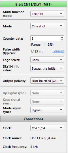
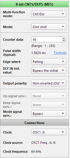
One-Shots set time intervals for the required number of pulses.
Digital multiplexers provide the passage of either one, or ten, or hundred pulses on CLK input of rheostat according to frequency detectors outputs.
2.1.2. Detents and Pulses per Revolution
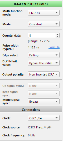
The encoder with a different number of pulses and detents (positions) was used in this project. With 15 pulses, you have two detents per full pulse. This means that for every pulse (or cycle) in the rotary encoder there are two detents: rising edge of the pulse (one change) and falling edge of the pulse (another change). If your rotary encoder has one detent per pulse, then it has two changes for every pulse. For this type of encoder, the design remains the same, except for Frequency Detectors and One-Shots settings. In their settings, Edge Select should be set “Falling” or “Rising”. In encoders where the number of pulses and detents do not match, Edge Select should be set to “Both”.
2.2. Potentiometer Mode
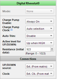
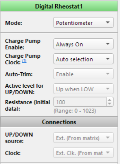
For this design, we used digital rheostats in potentiometer mode. This mode allows two 2-pin rheostats to work as one 3-pin potentiometer. When this mode is active (register [917] = 1), the user changes the value of the RH0 internal counter. In this mode, the value of the RH1 counter is the inverted value of the RH0 counter. Note that the RH0_B pin and the RH1_A pin must be connected externally.
2.3. Macrocells Settings
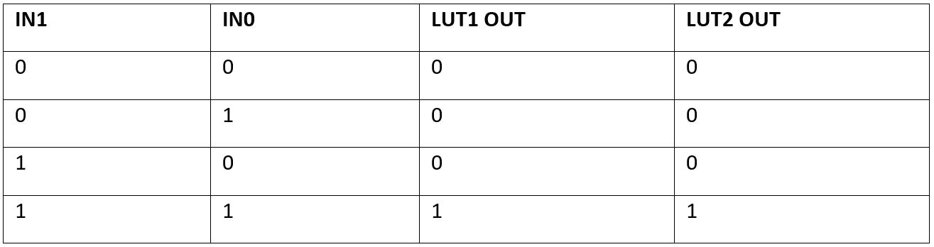
The following tables present 3-bit LUT1 and 3-bit LUT3 settings: Standard Gate – Multiplexer.
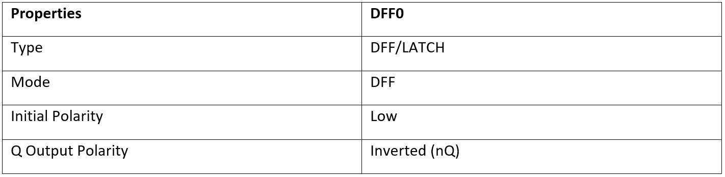
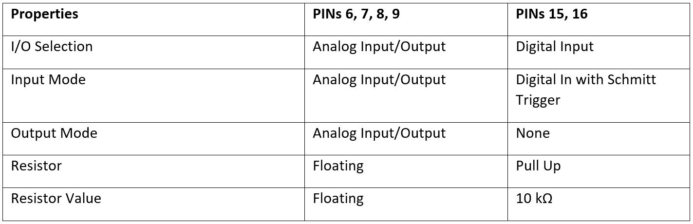
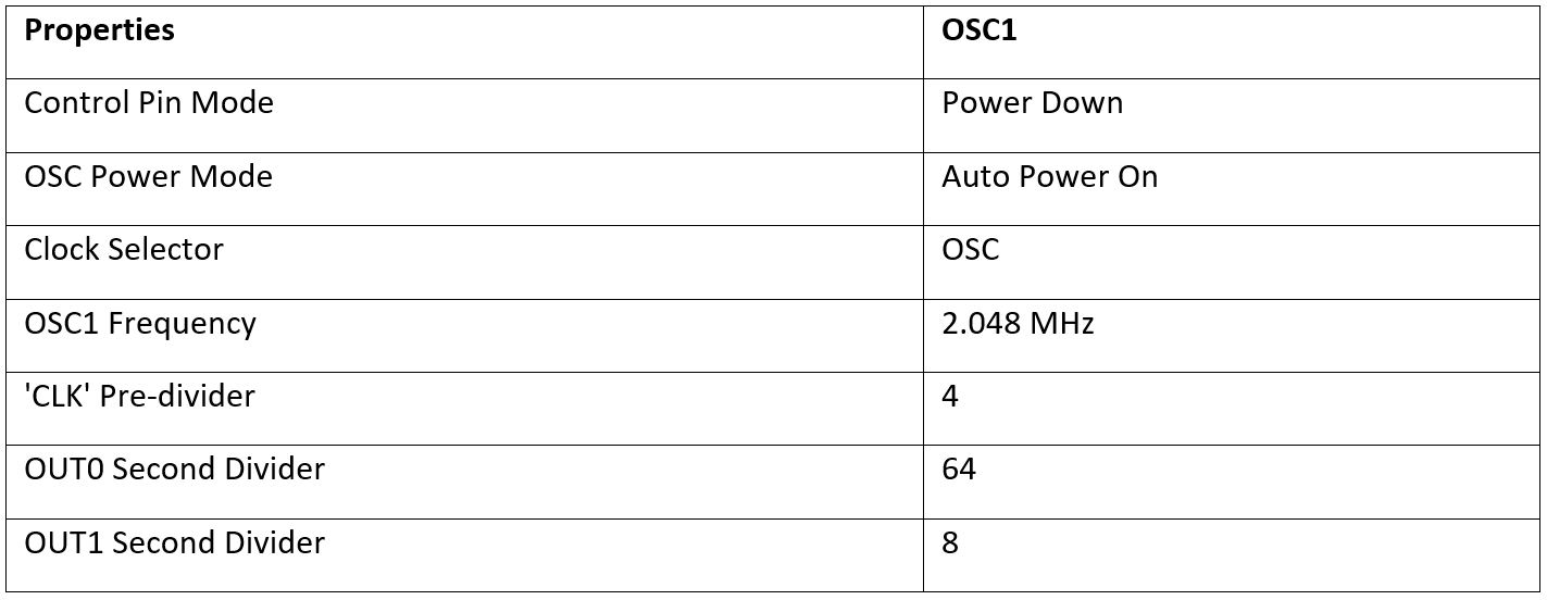
Table 1: 2-bit LUTs SettingsTable 2: DFF SettingsTable 3: PINs SettingsTable 4 OSC SettingsFigure 5a Digital Rheostats SettingsFigure 5b Digital Rheostats SettingsFigure 6a Delays SettingsFigure 6b Delays SettingsFigure 7a One Shots Settings when the Number of Pulses and Detents Do Not MatchFigure 7b One Shots Settings when the Number of Pulses and Detents Do Not MatchFigure 8a One Shots Settings when the Number of Pulses and Detents MatchFigure 8b One Shots Settings when the Number of Pulses and Detents MatchFigure 9a Frequency Detectors Settings when the Number of Pulses and Detents Do Not MatchFigure 9b Frequency Detectors Settings when the Number of Pulses and Detents Do Not MatchFigure 10a Frequency Detectors Settings when the Number of Pulses and Detents MatchFigure 10b Frequency Detectors Settings when the Number of Pulses and Detents Match
Conclusions
The SLG47004 has two digital rheostats which allow implementing a myriad of useful applications. A case in point is using digital rheostats to replace an analog potentiometer with the help of a modern encoder. This article illustrates how to use the SLG47004 to implement the adjustable voltage divider which is a versatile solution and can be applied to an adjustable power supply, amplifier’s gain control, and others. This solution is cost-effective and has low energy consumption.
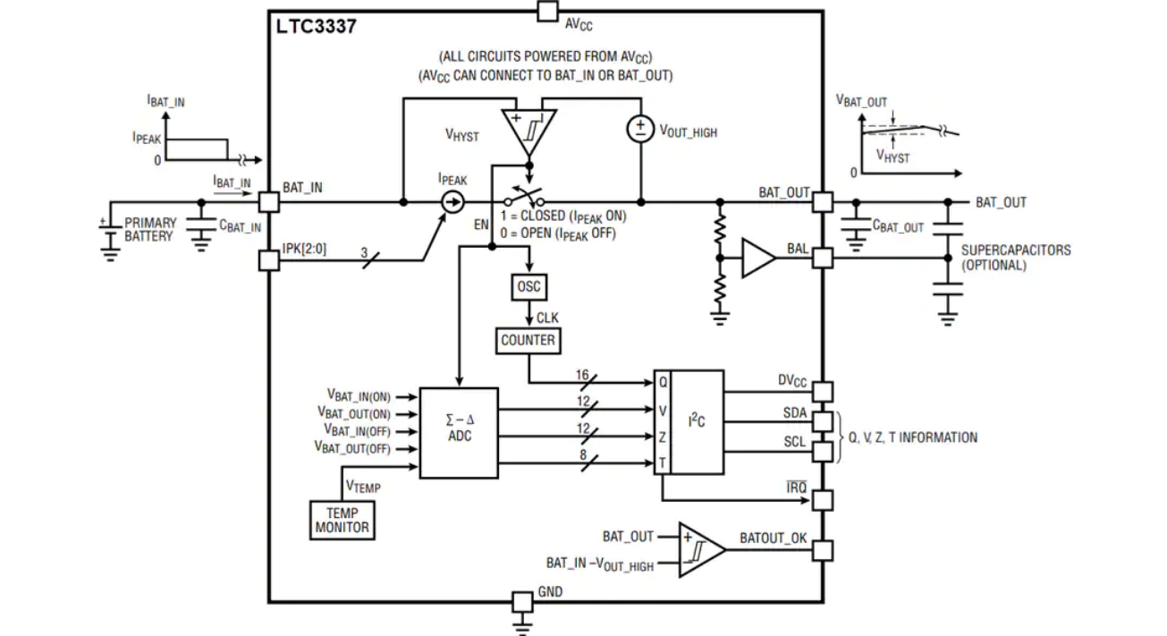
Analog Devices Inc. LTC3337 Primary Battery State of Health (SOH) Monitor provides accurate, real-time readings of battery cell discharge, voltage, impedance, and temperature. The LTC3337 is designed to be placed in series with a primary battery with minimal associated series voltage drop. This device integrates an infinite dynamic range coulomb counter that tallies all accumulated battery discharge and stores it in an internal register accessible via an I2C interface. A discharge alarm threshold based on this state of charge (SOC) is programmable. When it is reached, an interrupt is generated at the IRQ pin. Coulomb counter accuracy is constant down to no load.
To accommodate a wide range of primary battery inputs, the peak input current limit of the LTC3337 is pin selectable from 5mA to 100mA.
Coulombs can be calculated for either the BAT_IN or BAT_OUT pin, determined by the AVCC pin connection. A BAL pin is provided for applications utilizing a stack of two supercapacitors (optional) at the output.
The Analog Devices Inc. LTC3337 Primary Battery State of Health Monitor is available in a 12-lead Lead Frame Chip Scale Package (LFCSP) with an exposed pad for improved thermal performance.
Internal Diagram
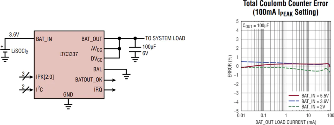
Application Diagram
Features
8.0V to 5.5V battery input voltage range
100nA quiescent current
8 primary battery peak input current limits
5mA, 10mA, 15mA, 20mA, 25mA, 50mA, 75mA, 100mA
SOH monitor for primary battery
Integrated coulomb counter (Q)
Additional monitors for battery voltage (V), battery impedance (Z), and temperature (T)
Integrated ±10mA supercapacitor balancer
Primary battery current (BAT_IN) or load current (BAT_OUT) is counted
Programmable coulomb counter prescaler for a wide range of battery sizes
Programmable discharge alarm threshold with interrupt output
I2C interface
-40°C to +125°C operating junction temperature range
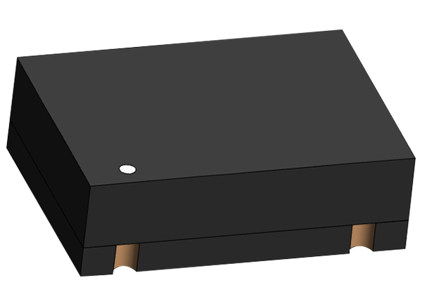
Abracon AST3TDA Precision SMD Crystal Oscillators are temperature-controlled crystal oscillators with wide operating temperatures and high stability. They feature a wide range of standard frequencies ranging from 10MHz to 50MHz, and voltage control as an available option. Abracon AST3TDA Temperature Controlled Crystal Oscillators high degree of precision suitable for network equipment, wireless communication, and autonomous technologies.
Features
-40°C to +105°C operating temperature range with high stability
Wide range of standard frequencies from 10MHz to 50MHz
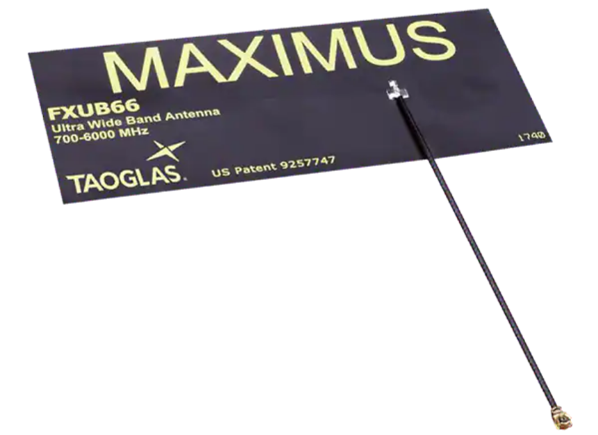
Taoglas FXUB66 Maximus Flexible Wideband 5G/4G Antenna is designed to cover all working frequencies in the 600MHz to 6000MHz spectrum, including cellular (5G/4G/3G/2G), NB-loT, Cat-M, Wi-Fi®, ISM, and GNSS bands. This flexible antenna features a unique hybrid design. Within one antenna structure, the electromagnetic waves travel in two predominant propagation modes – one for lower frequencies and the other for higher frequencies. Using the Maximus antenna in a device improves the radiated power and sensitivity while enabling the high throughput rates of broadband devices. The FXUB66 is ground plane independent and offers a 5dBi peak gain and more than 60% efficiency across all cellular bands. Taoglas FXUB66 Maximus Flexible Wideband 5G/4G Antenna comes with 3M adhesive tape for peel-and-stick mounting, 150mm of 1.37mm diameter coaxial cable, and an I-PEX MHF 4L (HSC compatible) connector.
Features
Ground plane independent
600MHz to 6000MHz wideband
5G/4G fully operational on all sub-6GHz bands
Efficiencies up to 80% on all cellular bands (600MHz to 6000MHz)
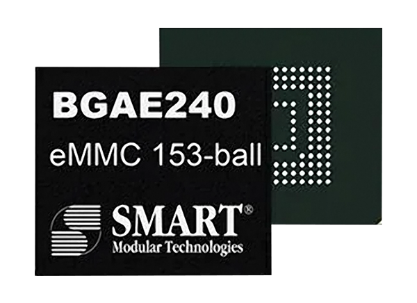
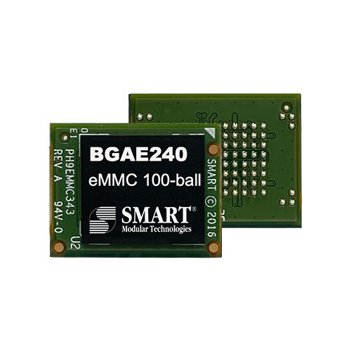
SMART Modular Technologies DuraFlash™ BGAE240 eMMCMemory is an industrial-grade embedded memory solution in a compact BGA (Ball Grid Array) package. The BGAE240 integrates 2D-MLC NAND Flash Memory, an embedded MMC (MultiMediaCard) controller, and advanced firmware into a single unit that provides stable, cost-effective, and high-density embedded storage. BGAE240 eMMC Memory is designed to meet the rigid requirements of the industrial, medical, and networking markets where technical support, extended life, and stable roadmaps are critical.
The SMART Modular Technologies DuraFlash BGAE240 eMMC Memory Modules are offered in capacities from 8GB to 64GB and are compliant with the JEDEC® v5.0 standard.
Features
Capacities from 8GB to 64GB
Up to 270MB/s read
Up to 95MB/s write
Compliant to JEDEC v5.0 standard
Pre-configurable to pSLC enhanced storage media mode
VCC = 3.3V and VCCQ = 3.3V or 1.8V
Specifications
Performance
eMMC v5.0 host interface
270MB/s maximum sequential read
95MB/s maximum sequential write
5.3K IOPS random read
1.2K IOPS random write
Reliability
10-year data retention
BCH error correction
Power
3.3V ±5% input voltage
Environmental and physical
Operating shock
1500g half-sine, 0.5msec
1 shock along each axis
X, Y, Z in each direction
Operating vibration
20G 80Hz to 2000Hz
1.52mm 20Hz to 80Hz, 3 axis
Industrial -40°C to +85°C operating temperature range
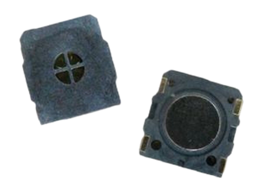
Advanced Acoustic Technology Corp. (AATC) Micro-Speakers offer a 110Hz to 20kHz frequency range, 72dB to 121dBA sound pressure level, and up to 100Ω impedance rating. These speakers come in circle, oval, rectangle, or square varieties and feature diameters from 10mm to 98mm. AATC Micro-Speakers are good at playing out multi-tone audio content, such as human voice and music.
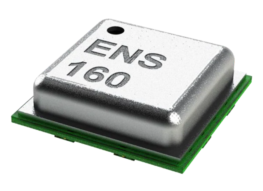
ScioSense ENS160 Digital Metal Oxide Multi-Gas Sensors offer a 1.67V to 1.98V supply voltage range and up to +85°C temperature rating. These sensors are based on metal oxide (MOX) technology with four MOX sensor elements, and each sensor element has independent hotplate control to detect a wide range of gases. The ENS160 series features TrueVOC™ air quality detection and supports intelligent algorithms, which calculate CO2equivalents, TVOC, and air quality indices (AQIs) and perform humidity and temperature compensation. ScioSense ENS160 Sensors are ideal for home appliances, IoT devices, building automation, and HVAC applications.
Features
TrueVOC air quality detection
Independent sensor heater control
Immunity to siloxanes and humidity
Hassle-free on-chip heater drive control and data processing
Interrupt on threshold for low-power applications.
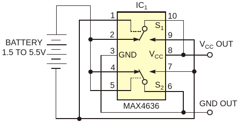
A universal problem in battery-operated devices is the threat of damage when an end-user (never an engineer) inserts the battery backward. You can avoid damage by inserting a single diode or by using a diode-bridge configuration, but those fixes waste power and reduce the supply voltage by adding one or two diode drops between the battery and the supply rail. An alternative solution not only protects against battery-reversal damage but also automatically corrects the reversal (Figure 1). To eliminate the voltage drops associated with discrete diodes, a low-on-resistance, DPDT (double-pole, double-throw) switch serves as a full-wave rectifier. When you insert the battery with the correct polarity as shown, the upper switch, S1, is in its normally closed state, because its control pin is in its low state. The resulting connection from Pin 2 to Pin 10 provides a low-impedance path from the battery to the VCC terminal. Conversely, the lower switch, S2, closes its normally open terminal (not as shown) because its control pin is in its high state. The resulting path from Pin 7 to Pin 6 connects the battery’s negative terminal to ground.
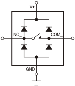
The ESD-protection diodes in IC1 guarantee start-up and act as a full-wave rectifier (Figure 2). MOSFETs internal to the analog switch turn on when the battery voltage exceeds 1 V. Their less-than-20-nsec turn-on time enables the circuit to maintain normal operation by quickly swapping the leads of a reversed-polarity battery connection. The circuit resistance is proportional to the battery voltage. When the circuit operates from four NiCd, NiMH, or alkaline cells, the resistance in each leg of the rectifier is 2.5 Ω (5 Ω total). Operation with a two-cell battery (2.4 to 3 V) yields a total resistance of 10 Ω. IC1 is rated for operation to 5.5 V with 30-mA continuous current, making the circuit useful for cordless phones, portable audio equipment, handheld electronics, and other light- to medium-current applications. IC1‘s miniature 10-pin µMAX package takes less space than four through-hole signal diodes and is almost as small as two SOT-23 dual signal diodes.
The NCP716BC is a 150 mA LDO Linear Voltage Regulator with a wide input voltage range from 2.5V up to 24 V
The NCP716BC is a 150 mA LDO Linear Voltage Regulator with a wide input voltage range from 2.5V up to 24 V. The device comes in a TSOP-5/SOT-23-5 package and is an extension of the NCP715, NCP716, NCP716B, and NCP718 series, which all feature an input voltage range of up to 24 V. It is a very stable and accurate device with ultra-low ground current consumption and comes with several protection features such as thermal shutdown and current limit protection.
Key features
Wide Iiput voltage range: 2.5 V to 24 V
Ultra-Low quiescent current: 3.2 µA typical, 4.7 µA maximum over temperature
Compact TSOP-5/SOT-23-5 package
Thermal shutdown and current limit protection
Additional features
Fixed voltage options available:
3.0 V, 3.3 V, 3.45 V and 5.0 V
±2% accuracy over the full temperature range
Noise: 115 μVRMS from 200 Hz to 100 kHz
Cross-reference and pin-to-pin replacement for TLV704