Meet the New 5G Ready Carrier Board from AAEON’s UP! Bridge the Gap

Netherlands bands Embedded computing solutions manufacturer, AAEON Technology Europe, last week announced the launch of their latest carrier board; the UP Connect Plus, which was designed to add 5G capability to its popular UP Core Plus and UP Xtreme platforms.

The UP Core Plus, an ultra-compact, high-performance, and fanless edge computing module, and the Up Xtreme, an even more powerful Edge AI inference solution, both, on different levels, provide users with the computing power needed to develop AI and IoT powered smart applications that businesses depend on to help them optimize, monitor, manage and secure their operations.  However, as this number of devices grow, with increased interconnectivity, network traffic, and amount of data being shared, etc., solution providers and users are constantly looking for better ways to overcome latency, improve bandwidth to ensure seamless movement of data, and overall network reliability which is all of which 5G promises.

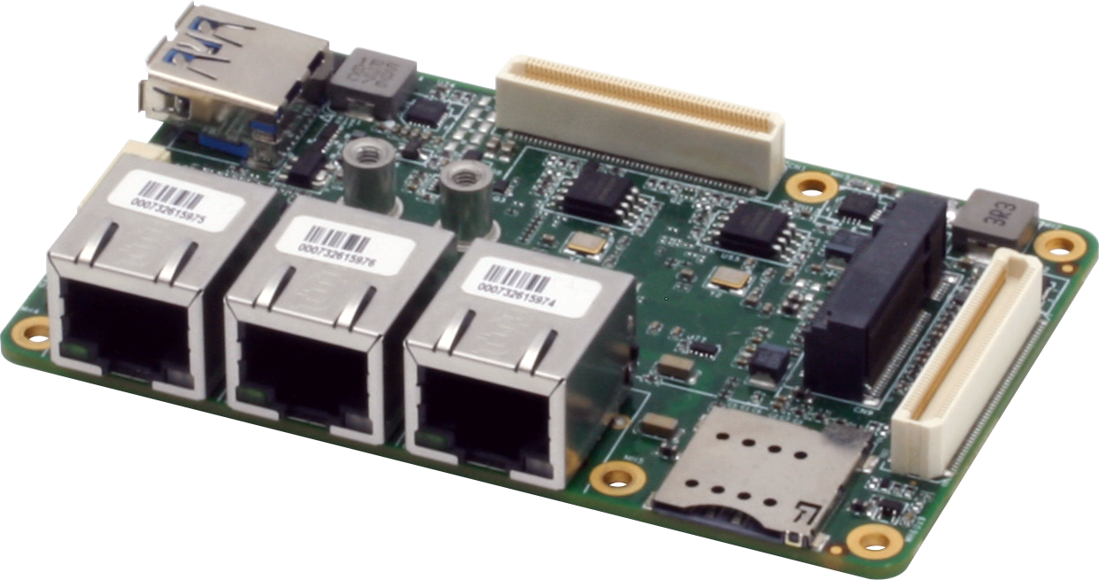
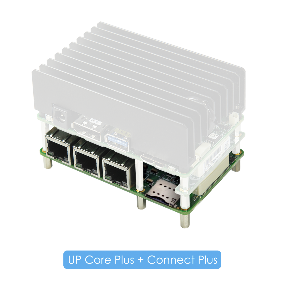
Meeting this demand is one of the major reasons why the Up Connect Plus was developed to provide access to 5G capabilities for the Up Core Plus and UP Xtreme platforms which already come with WiFi and LAN onboard.  The Up Connect Plus provides a 5G compatible port via its M.2 3042/3052 colayo through which users can add a 5G module card and bring astonishing 5G speeds to any UP Core Plus or UPXtreme based AI application.

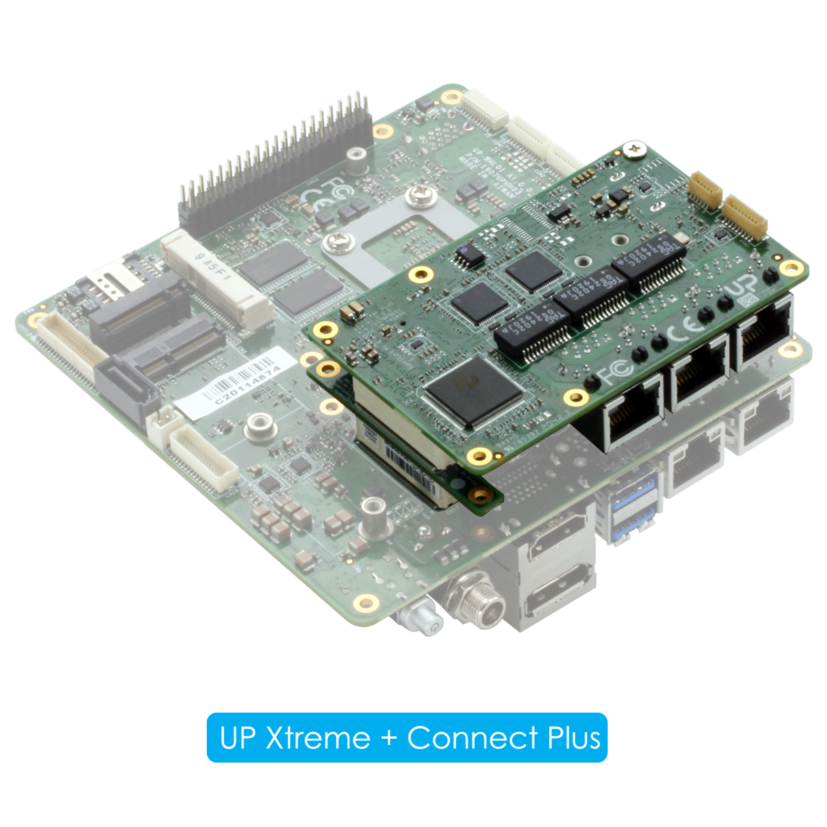
Asides from the 5G Port, the UP Connect Plus also offers three additional Gigabit LAN ports to extend functionalities of the UP Core Plus and UP Xtreme platforms. With users being given the opportunity to choose between two types of Intel® Ethernet ports that deliver gigabit speeds as the UP Connect Plus comes in two versions including; the UP Connect Plus i211 which features three Intel® Ethernet Controller I211-AT Gigabits ports and the UP Connect Plus i210 which features three Intel® Ethernet Controller I210-IT ports with Time-Sensitive Networking (TSN) and support for a wide temperature range which comes in hand in industrial applications that require synchronization and precision timing.

Solution developers can use TSN together with real-time features on Intel® architecture to synchronize networks of devices for improved timely behavior of industrial systems across applications like Smart factories, Cobots, and general autonomous systems.

Highlight specifications of the Up Connect Plus include;

  • Support for 5G module (M.2 3042/3052 colay) with micro-SIM card port
  • 3x Intel® Ethernet Controller I210-IT (wide temperature and TSN) OR 3x Intel® Ethernet Controller I211-AT
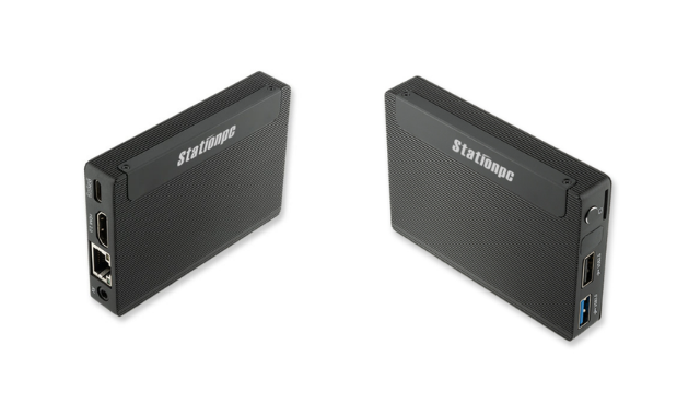
  • USB 3.0 Type-A (UP Core Plus only)
  • 1x 2 channel PCIe Switch
  • Suitability for Industrial Operations with operating temperature between 32°F ~ 140°F (0°C ~ 60°C)

The UP Connect Plus is now available for sale at AAEON’s UP! Bridge the Gap store, with prices starting from $84 without shipping.

More information on UP Connect Plus can be found on the product’s announcement page on AAEON’s UP-Board website. 

Get this sunlight readable display for Raspberry Pi at just $110

Sunlight readable display may not be a new concept for most developers working on the Raspberry Pi single-board computers. For those who do not know how it works, then as the name suggests, a sunlight-readable display operates in direct sunlight or harsh light conditions. Those working on any application that requires capacitive touch LCD compatible with Raspberry Pi have seen several other products with one, especially from SparkFun Capacitive Sunlight Readable LCD Board if you are only looking for a cheap yet powerful capacitive touch screen display for your Raspberry Pi 3/4 for any industrial or commercial applications.

This newly launched Sunlight Readable Touchscreen HDMI Display comes with a decent-sized 5-inch screen with capabilities to operate on most SBCs like the Raspberry Pi, BB Black, Banana Pi, and other Mini PCs. With these points, we have some specifications that you’d want to look at before getting into the customizable capabilities of the sunlight-readable display.

Specifications:

  • Product: MakerPlane Sunlight Readable Display
  • Dimensions: 121mm x 95.2mm
  • Resolution: 800 x 480 crisp
  • Screen size: 5-inch IPS
  • Aspect ratio: 16:10
  • Brightness: 1100 cd/m2
  • View angle: Horizontal:170° Vertical:150°
  • Interface: HDMI
  • Touch type: Single point capacitive touch screen
  • Module structure: LCD Display + CTP Touch + PCB
Sunlight Readable Display Applications
MakerPlane’s LCD display featuring an avionics instrument

Along with these specifications, when you buy the product, one important thing is the powering options for the hardware. The manufacturer has provided the sunlight-readable display with a 5V 2A minimum power supply through a micro-USB or GPIO module. With all these best-in-class specifications, the buyer gets several other things in the package included, has one 5-Inch Screen, an HDMI connector, a Micro HDMI, a connector screws pack (4pcs), and a 16GB SDcard storage.

Comparison between a normal LCD screen and MakerPlane’s sunlight-readable display.

MakerPlane sunlight-readable display compared to other displays, seems to be easy on your eyes that makes it a perfect choice for gaming or always-on display applications. With such displays, the designers can design navigational instruments or even display news headlines. Also, with easy interfacing, it becomes easy to explore all the capabilities that aid your applications with minimal cost than other displays. With all these features and peculiarities, the users are pretty happy with the designed product that gives you not only a wide viewing angle but also good brightness at a reasonable price.

Video

When it comes to customizing the display, you can control the brightness using PWM. But when doing this, make sure you look at the detailed guide on the product page because the commands for Raspberry Pi 3B/3B+ are different from the latest Raspberry Pi 4B. Those designers working on the Raspberry Pi 4B need to update the wiringPi GPIO library, which can be done with the SBC connecting to the internet. With similar commands, you can control the brightness by keeping the X value between 0 to 1024, with 1024 being the darkest and 0 being the brightest.

Photos

For Raspberry Pi 3B/3B+

gpio -g pwm 18 1024
gpio -g mode 18 pwm
gpio pwmc 1000
gpio -g pwm 18 X

For Raspberry Pi 4B

gpio -g mode 18 pwm
gpio pwmc 4095
gpio -g pwm 18 X

You can also rotate the display with some simple commands provided by the manufacturer, but note that you also need to configure for the touch with these commands, which does not automatically change with the screen rotation. For this, you can refer to the guide with detailed commands but only for Raspberry Pi.

If you are looking to buy this reasonably yet powerful display for your favorite SBC, then head to the product page available for sale at just $109.95 with additional shipping charges.

3 Phase AC input – DC Output – High Voltage DC Power Supply (2KW)

Although this power supply design is specific to the Intelligent Power Modules (IPM) VFD drives, high voltage boost converters, high voltage battery chargers, etc, the concept and circuit design may be used for any power supply that requires a high voltage output of up to 800V DC and 4 A. Since it is an unregulated power supply the output will depend on AC input voltage. The circuitry includes a passive EMI filter consisting of elements C8, C9, C4, T1, and L1.  Bridge rectifier D1, R1 for inrush current protection, and a relay RL1 for soft powering up and reducing conduction losses in steady-state. 4 x electrolytic capacitors C2, C3, C6, C7 are used for buffering the rectified DC bus voltage, bleeding resistors R1, and R2 provided to discharge the DC bus capacitor after power off. It is advisable to use a heatsink for the bridge rectifier. Inrush current circuit requires 12-15V DC @ 80mA. Choose appropriate fuse as per current requirement. The relay takes care of the inrush current. It is important to switch ON the 12V-15V DC and 3phase power same time.

We have tested this power supply with Input 3 Phase 430V AC, Output 620V DC, Continued Current 5A, but it is advisable to use it at max 3A continued current.

Application: VFD Drives, AC Servo Drivers, High Voltage Battery Chargers, ZVS Drivers, High Voltage Inverters, High Voltage DC-DC Converters

Safety precautions

The board operates at lethal voltages and has bulk capacitors that store significant charges. Accidental contact can lead to lab equipment damage, personnel injury, and may be fatal. Please be exceptionally careful when probing and handling this board. Always observe normal laboratory precautions.

Features

  • Nominal Input Voltage 3 Phase 100V to 480V AC
  • Output Depend on input AC Supply
  • Output Current Continues 3Amps (Maximum 5 Amps)
  • On Board EMI Filter
  • On Board High wattage resistor for inrush Current
  • On Board Relay for soft powering up and reducing Power Losses
  • On Board Fuse for Short Circuit/Over Current Protection
  • Screw Terminals (Barrier) for Easy Connections
  • Logic Supply 12-15V for inrush Control Relay Circuit
  • PCB dimensions: 206.37 x 75.56 mm

Schematic

Parts List

NO.QNTYREF.DESC.MANUFACTURERSUPPLIERSUPPLIER PART NO
11CN13 PIN BARRIER STRIP PITCH 9.5MMON SHORE TECHDIGIKEYED2972-ND
21CN24 PIN BARRIER STRIP PITCH 9.5MMON SHORE TECHDIGIKEYED2973-ND
31CN34 MALE HEADER PITCH 2.54MMWURTHDIGIKEY732-5317-ND
43C1,C4,C50.1uF/1KVKEMETDIGIKEY399-PHE450PD6100JR06L2-ND
54C2,C3,C6,C7470uF/450VRUBYCONDIGIKEY1189-1975-ND
62C8,C94.7KPF/3KVTDKDIGIKEY445-181053-ND
72C10,C1110uF/25VNICHICONDIGIKEY493-5953-ND
1D1GUO40-12NO1IXYSDIGIKEYGUO40-12NO1-ND
2D2,D31N4007DIODE INCORPDIGIKEYS1MBDITR-ND
1F1COVER FUSEKEYSTONEDIGIKEY36-3576C-ND
1F1FUSEKEYSTONEDIGIKEY36-3576-ND
1F1FUSE LITTILE FUSEDIGIKEY0FLQ015.HXR-ND
1L1220uH/7.1AWURTHDIGIKEY732-2285-ND
1Q1BC817NEXPERIADIGIKEY1727-2919-1-ND
1RL1Relay 12V TEDIGIKEYPB2355-ND
1R1100E/10WVISHAYDIGIKEYMRA12-100-ND
2R2,R3270K/3WVISHAYDIGIKEYBC270KW-3JCT-ND
1R410K 5% SMD SIZE 0805MURATA/YAGEODIGIKEY
1R51K 5% SMD SIZE 0805MURATA/YAGEODIGIKEY
1T11MH 10A COMMON MODE CHOKEWURTHDIGIKEY732-1449-ND

Connections

Block Diagram

Gerber View

Photos

Video


GUO40-12NO1 Datasheet

Clock Multiplier – Crystal Frequency Generator using PT7C4511

This is an easy-to-build project and it is the most cost-effective and high-performance frequency multiplier, which instigates analog phase lock loop techniques. The circuit provides high-quality, high-frequency output from lower frequency crystal or clock input. The project can be used as a crystal frequency oscillator, clock multiplier and frequency translation. Using phase-locked-loop (PLL) techniques, the device uses a standard fundamental mode, inexpensive crystal to produce an output clock up to 200Mhz.  On-board jumpers are provided to select from nine different multiplication factors, which output many common frequencies.  The device also has an output enable pin that tri-states the clock output when the enable pin is taken low. The chip is intended for clock generation and frequency translation with low output jitter.

Refer to the table below for jumper settings to change the frequency multiplexing.

  • Connections for Clock Input: CN1 Clock input 1- 50Mhz, Use J2, and J3 for frequency output settings.
  • For Internal Clock Generator: Use crystal Y1, Capacitor C1, and C2

A parallel resonant, fundamental mode crystal should be used. The device crystal connections and capacitor connections are provided. These capacitors are used to adjust the stray capacitance of the board to match the nominally required crystal load capacitance. Because load capacitance can be only be increased in this trimming process. Crystal Capacitors, if needed, must be connected from each of the pins X1 and X2 to the ground.

The value (in pF) of these crystal capacitors should equal C-L x 2 in this equation, C-L=crystal capacitance in pF. Example: For a crystal with a 15pF load capacitance, each crystal capacitor would be 30pF.   

Features

  • Power Supply 5V DC (Range 3 to 5 V DC)
  • Zero ppm multiplication error
  • Output Load 12mA Max
  • Input crystal frequency of 5Mhz to 30Mhz
  • Output Duty Cycle 50%
  • Input Clock Frequency of 1-50Mhz
  • Output Clock Frequencies up to 200Mhz
  • 9 Selectable Frequencies Controlled by Jumper
  • Peak to Peak Jitter Less than 200ps over 200ns Interval (100-200Mhz)
  • Low Period Jitter 20ps (100-200Mhz)
  • Tri-States Output for Board Level Testing
  • PCB dimensions: 25.72 x 17.94 mm

Schematic

Parts List

SR.QNTY.REF.DESCMANUFACTURERSUPPLIERSUPPLIER PART NO
11CN12 PIN MALE HEADER CONNECTOR PITCH 2.54MM WURTHDIGIKEY732-5315-ND
21CN24 PIN MALE HEADER CONNECTOR PITCH 2.54MM WURTHDIGIKEY732-5317-ND
33Y1,C1,C2DNP
41C310uF/16VMURATA/YAGEODIGIKEY
51C40.1uF/50VMURATA/YAGEODIGIKEY
61D1LED RED SMD SIZE 0805OSRAMDIGIKEY475-1278-1-ND
71J12 PIN MALE HEADER PITCH 2.54MM DIGIKEY732-5315-ND
82J2,J33 PIN MALE HEADER PITCH 2.54MMDIGIKEY732-5316-ND
91R11K 5% SMD SIZE 0805MURATA/YAGEODIGIKEY
101U1PT7C4511 SOIC8DIODE INC.DIGIKEYPT7C4511WEXDICT-ND
113SHUNTJUMPER-SHUNTSULLINSDIGIKEYS9001-ND

Connections

Jumper Selection

Block Diagram

Gerber View

Photos

Video

PT7C4511 Datasheet

First commercially available superconducting quantum processor

The Dutch startup QuantWare has announced the launch of the world’s first commercially available superconducting processor for quantum computers (QPU).

This is the first time superconducting quantum processors have been made available ‘off the shelf’, and is being seen as a development with the potential to significantly accelerate the quantum computing revolution.

Quantum technology promises to significantly expand the amount of data computers are able to process, which could have huge implications across A.I., medicine, business intelligence, and cybersecurity. However, in what is still a new, developing industry scaling is difficult.

Companies building parts for quantum computers need qubits, the microscopic objects that make quantum computing possible, but it is often cost prohibitive for them to produce them themselves. QuantWare’s superconducting QPUs are intended to eliminate that barrier and may be instrumental in accelerating the development of the quantum computer market.

Superconducting is the leading and most mature approach to quantum processors – Google achieved “quantum supremacy” in 2019 using superconducting QPUs. While other QPUs are already available “off the shelf”, this is the first time a superconducting QPU has been easily available in productised form, leveling the playing field for quantum experimentation.

QuantWare’s proprietary product, Soprano, is a 5-qubit QPU which is seen as sufficient for the immediate customer base QuantWare expects to attract, namely research institutions and university labs.

“The race towards useful Quantum Computation is heating up, but still reserved to a small group of companies. By making QPUs more available, we will speed up the development of practical quantum-driven solutions to the world’s biggest problems.”

said QuantWare co-founder Dr. Alessandro Bruno.

Another way to achieve “Quantum Advantage” is by designing a chip specifically for a particular application and QuantWare is looking to exploit this by making co-designed QPUs together with software companies to allow them to develop processors specialized in their algorithms.

more information: www.quantware.eu

RAK3172 – WisDuo LPWAN Module

The RAK3172 LoRa Module includes a STM32WLE5CC chip, which supports eight (8) spreading factors (SF5 ~ SF12) and signal bandwidth that can be adjusted between 7.8 kHz to 500 kHz. It has Ultra-Low Power Consumption of 1.69 μA in sleep mode, but during the Transmit Mode, it can reach the maximum output power of 22 dBm. As a receiver, it can achieve a sensitivity of -148 dBm.

The module complies with Class A, ClassB, Class C of LoRaWAN 1.0.3 specifications, and it also supports LoRa Point to Point (P2P) communications. The module is suitable for various applications that require long-range data acquisition and low power consumption, such as smart meters, supply chain and logistics tracking, agricultural sensors, and smart cities.

You can configure the mode and operation of the RAK3172 module using RAK3172 AT Commands via a UART interface. Also, it offers low-power features that are very suitable for battery-powered applications.

Product Features

  • LoRa module for Smart City, Smart Agriculture, Smart Industry
  • Compact Form Factor: 15 x 15.5 x 3.5 mm 32 Pin Stamp Pad for PCB SMT mounting I/O ports: UART/I2C/SPI/ADC/GPIO
  • Temperature range: -35 °C to +85 °C
  • Supply voltage: 2.0 ~ 3.6 V
  • Frequency range: 150 MHz to 960 MHz
  • Low-Power Wireless Systems with 7.8 kHz to 500 kHz Bandwidth
  • Ultra-Low Power Consumption 1.69 μA in sleep mode
  • Core: ARM 32-bit Cortex – M4 with MPU Up to 256 KB flash memory with ECC
  • 64 KB RAM
  • AT commands control interface
  • Supported bands: (EU433, CN470, RU864, IN865, EU868, AU915, US915, KR920, and AS923)

Pinout

More information

Via CNX Software

https://www.cnx-software.com/2021/07/16/6-rak3172-wisduo-lorawan-module-features-stmicro-stm32wl-lora-soc/

Texas Instruments TMCS1107 Hall-Effect Current Sensor is galvanically isolated

Texas Instruments TMCS1107 Hall-Effect Current Sensor is a galvanically isolated Hall-effect current sensor capable of DC or AC current measurement with high accuracy, excellent linearity, and temperature stability. A low-drift, temperature-compensated signal chain provides < 3% full-scale error across the device temperature range.

The input current flows through an internal 1.8mΩ conductor that generates a magnetic field measured by an integrated Hall-effect sensor. This structure eliminates external concentrators and simplifies design. A low conductor resistance minimizes power loss and thermal dissipation. Inherent galvanic insulation provides a 420V lifetime working voltage and 3kVRMS basic isolation between the current path and circuitry. Integrated electrical shielding enables excellent common-mode rejection and transient immunity.

The output voltage is proportional to the input current with multiple sensitivity options. Fixed sensitivity allows the TMCS1107 to operate from a single 3V to 5.5V power supply, eliminates ratiometry errors, and improves supply noise rejection. The current polarity is considered positive when flowing into the positive input pin. Both unidirectional and bidirectional sensing variants are available. The Texas Instruments TMCS1107 draws a maximum supply current of 6mA, and all sensitivity options are specified over the operating temperature range of –40°C to +125°C.

System Diagram

Features

  • ±1% typical, ±3% maximum, –40°C to 125°C total error
    • ±0.9% sensitivity error
    • 40mA offset error
    • 0.2mA/°C offset drift
    • 0.5% linearity error
  • Multiple sensitivity options
    • TMCS1107A1B/U – 50mV/A
    • TMCS1107A2B/U – 100mV/A
    • TMCS1107A3B/U – 200mV/A
    • TMCS1107A4B/U – 400mV/A
  • Zero drift internal reference
  • Bidirectional and unidirectional current sensing
  • 3V to 5.5V operating supply range
  • 80kHz signal bandwidth
  • 3kVRMS isolation rating
  • Robust 420V lifetime working voltage
  • Safety related certifications
    • UL 1577 component recognition program
    • IEC/CB 62368-1

Block Diagram

more information: https://www.ti.com/product/TMCS1107

LTC7818 – 40V, Low IQ, 3MHz, Triple Output Buck/Buck/Boost Synchronous Controller

Analog Devices LTC7818 Triple Output Synchronous Controllers are high-performance synchronous DC/DC switching regulator controllers that drive all N-channel power MOSFET stages. Its constant frequency current mode architecture allows a phase-lockable switching frequency of up to 3MHz. The LTC7818 operates from a wide 4.5V to 40V input supply range. When biased from the output of the boost converter or another auxiliary supply, the LTC7818 can operate from an input supply as low as 1V after start-up.

The very low no-load quiescent current extends operating run time in battery-powered systems. OPTI-LOOP® compensation allows the transient response to be optimized over a wide range of output capacitance and ESR values. The LTC7818 features a precision 0.8V reference for the bucks, 1.2V reference for the boost, and a power-good output indicator. The LTC7818 additionally features spread-spectrum operation which significantly reduces the peak radiated and conducted noise on both the input and output supplies, making it easier to comply with electromagnetic interference (EMI) standards.

Application Diagram

Package

Features

  • Dual buck plus single boost synchronous controllers
  • Low operating IQ
    • 14μA (14V to 3.3V, channel 1 on)
  • Outputs remain in regulation through cold crank down to 1V input supply voltage
  • 4.5V to 40V wide bias input voltage range
  • Buck and boost output voltages up to 40V
  • Spread spectrum operation
  • RSENSE or DCR current sensing
  • 100% duty cycle for boost synchronous MOSFET
  • Programmable fixed frequency (100kHz to 3MHz)
  • Phase-lockable frequency (100kHz to 3MHz)
  • Selectable continuous, pulse-skipping, or low ripple burst mode operation at light loads
  • Boost channel current monitor output
  • 1.5μA low shutdown IQ
  • Small 40-lead 6mm×6mm QFN package

more information: https://www.analog.com/en/products/ltc7818.html

Firefly’s ALL NEW Station M2 Featuring RK3566 SoC, Runs Linux and Android

Station M2

We have already seen Firefly’s RK3566-based mini-computer that was designed to compete with the powerful Raspberry Pi 4. With support from the community, Firefly has now released a new mini-PC, Station M2 based on the high performance, low power powerful Rockchip SoC, RK3566 that can now run Linux or Android. The board also supports 8GB RAM and 128GB eMMC storage for the user to play high-end applications on this tiny mini-PC.

The SoC features a quad-core 64-bit Cortex-A55 processor, clocked up to 1.8 GHz frequency along with the Mali-G52 GPU. The ultra-compact mini-PC is a successor to their Station M1 mini-PC that was launched last year and built around Rockchip’s RK3328. The station M1 was not as powerful as this release as it came with only 2GB/4GB RAM and 16GB storage.

Some of the key upgrades to Station M2 include the addition of an M.2 2242 slot for NVMe SSDs and also support more SPI flash storage of up to 16M. In terms of wireless connectivity, the Station M2 gets faster dual-band Wi-Fi 802.11 with Bluetooth 5.0. Also, as mentioned earlier, the successor Station M2 now comes with a configuration of 8GB/128GB.

Station M2 Side

Features:

  • CPU: Rockchip RK3356 22nm fabricated SoC featuring a quad-core 64-bit Cortex-A55 processor, clocked up to 1.8 GHz
  • GPU: Mali-G52 that supports OpenGL ES1.1/ 2.0./ 3.2, OpenCL 2.0, Vulkan 1.1
  • NPU: 0.8 TOPS @INT8, integrated AI accelerator RKNN NPU supporting Caffe, TensorFlow, TFLite, ONNX, PyTorch, Keras, Darknet
  • VPU: Supports 4K60fps H.265/H.264/VP9 video decoding, and 1080p100fps
  • Storage: 32GB/ 64GB/ 128GB eMMC, M.2 PCIe 2.0, TF-Card Slot
  • Memory: 2GB/ 4GB/ 8GB LPDD4 RAM
  • Wireless Connectivity: Wi-Fi 802.11a/b/g/n, Bluetooth 5.0
  • Interfaces: HDMI 2.0, USB 3.0, USB 2.0, MIPI DSI, MIPI CSI, SPI, I2C, UART, ADC, PWM, GPIO, PCIe, I2S.
  • OS Support: Android 11.0, Ubuntu 18.04, Buildroot + QT, Station OS
  • Size: 93.8mm x 65.0mm x 15.8mm
  • Power: 5V via Type-C port

The Station M2 mini-PC interestingly supports several OS including the Station OS that offers a variety of applications and seamless switching between the desktop and media modes. Along with this, the hardware also supports Android 11.0 and Ubuntu 18.04 which is the most stable Linux Distro. With HDMI 2.0 onboard, users can take advantage and live stream video files using video decoding H.265 and 8GB RAM.

The mini-PC is now up for sale at $79 for 2GB/32GB, $105 for 4GB/32GB, and $149 for 8GB/64GB variant. Head to the product page for more hardware specifications.

Explore AI capabilities on Raspberry Pi Zero W with Google’s Coral USB Accelerator

Maple Syrup Pi Camera Image

For real-time AI applications, it is important to process incoming data using a trained neural network model. For faster data processing, the introduction to AI inference at cloud did support many aspects, increasing efficiency, but the need to process the data at the end device has become vital. To serve this purpose, we have AI inference at the edge. With AI inference at the edge, the market for real-time data processing and obtaining quick results has increased performance. When it comes to AI inference at the edge, several ASICs in the market are custom-built for this purpose. Google introduced an Edge TPU application-specific integrated circuit designed to run inference at the edge.

There have been several designs using Google’s Edge TPU, but this specific project, Maple Syrup Pi Camera, an AIoT smart camera has caught the eye of the makers’ community due to its use of Raspberry Pi Zero W for AI inference at the edge. We don’t usually see these SBCs used to run inference at the edge due to their low processing capabilities. For specific AI purposes, we have several powerful SBCs in the market designed for this use case. [Ricardo] has developed this smart camera that uses a Coral USB accelerator that is connected with the Raspberry Pi Zero W.

Maple Syrup Pi Camera Circuit

This interesting project of exploring the power of Raspberry Pi Zero W has employed the Raspberry Pi Camera along with the Raspberry Pi Zero flat cable. The software provided by the designer on GitHub, recommends you to use 8GB of storage Micro SDCard but it depends on the firmware you will be using. Since the SBC does not come with a power protection circuit, the board connects the USB power directly to the power supply. “That means the Coral USB Accelerator will be directly connected to the power supply, allowing it to drain as much current as of the power supply and impedance of microUSB + PCB traces allow it,” [Ricardo] explains:

In my experiments, the Maple-Syrup-Pi-Camera consumes around 160mA at 5V when idle (800mW).

This exploration of machine learning capabilities could be a good start for those looking to use Google Coral USB Accelerator with their favorite Raspberry Pi. Such projects can be used for object detection or even processing the incoming data on edge and giving the required output through trained models. Such projects can be used in the area of real-time AI-vision applications. For more information on this open-source project, head to the GitHub repository.

Maple Syrup Pi Camera Final

TOP PCB Companies