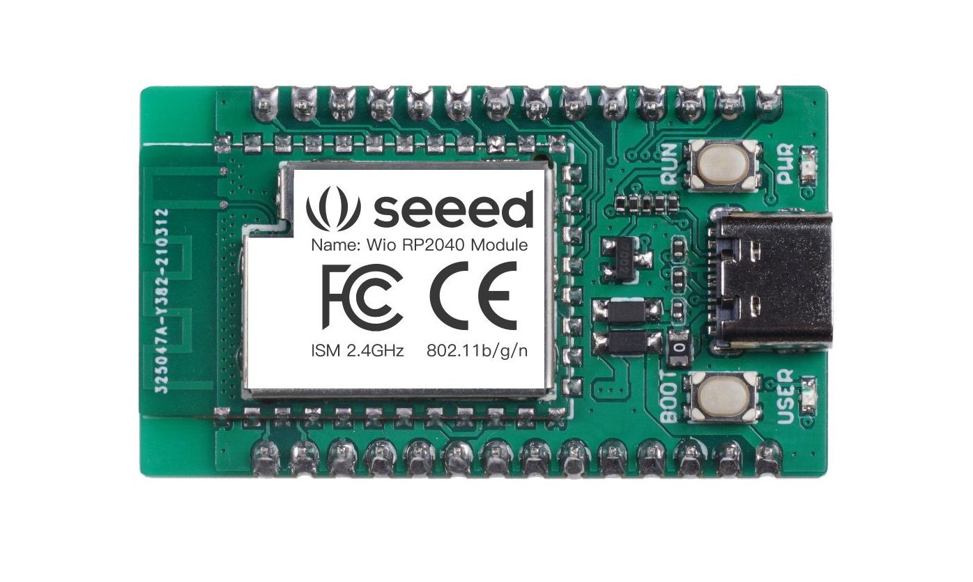
Yet another development board featuring Raspberry Pi’s RP2040 SoC with WiFi capabilities. The Wio RP2040 Mini Development board by Seeed Studio comes in a smaller form factor for compact wireless applications. The powerful RP2040 SoC by Raspberry Pi and Seeed’s Studio’s WiFi module bring out the best of both worlds.
We recently saw the Arduino Nano RP2040 Connect board offering WiFi and Bluetooth functionality along with various onboard sensors. It also comes with a u-blox NINA-W102 radio module compatible with Arduino Cloud. Hence, this justifies the high cost of the board as it can support a wide range of applications. But if you want your applications to limit to only WiFI functionalities then Seeed Studio’s Wio RP2040 Mini Development Board would be a reasonable choice for you. As it costs half the price of Arduino’s RP2040 Connect Board.
Technical Specifications of Wio RP2040 Mini Development Board
RP2040 microcontroller featuring dual Cortex M0+ processors working up to 133 MHz along with 264 KB of embedded SRAM in 6 banks.
QSPI Flash Memory of 2MB.
On-board USB-C Connector for programming with USB 1.1 Host/Device functionality.
20x multifunctional GPIO Pins for basic input-output functions.
2.4GHz wireless connectivity supporting IEEE802.11 b/g/n along with the Ap & Station mode.
Onboard buttons like Boot and Reset(RUN).
Two power supply methods; 5V via USB-C port and VIN(5V~3.6V) and GND header pins.
Talking more about the WiFi functionality, it supports the frequency range from 2.4~2.4835 GHz. This connectivity supports IEEE802.11 b/g/n standards. The board can act as both Access Point as well as Station. The board creates a WiFi zone when it is in Access Point mode and it acts as a client device and connects to the WiFi network in Station mode.
Seeed Studio explains “ Wio RP2040 mini development board has rich interfaces, including 28 GPIO PINs (19 PINs support PIO and PWM), 2 UART, 4 ADC, 2 SPI, 2 I2C. Some pins can be multiplexed, such as GP12 and GP13 with I2C, SPI, UART functions. That’s why 28 GPIO PINs can achieve more I/O PINs and interfaces.”
The board is compatible with the beginner-friendly Thonny code editor, which also used by Raspberry Pi Pico. Hence, the transition of the Pi Pico projects to Pico IoT projects becomes simple to program. Discussing further, Wio RP2040 mini development board supports programming in C/C++ and MicroPython.
Currently, the Wio RP2040 mini development board is out of stock due to the unavailability of the RP2040 module. However, the modules are expected to be ready by September 2021. The board costs $12.95 and you can buy it from Seeed Studio once it is available.
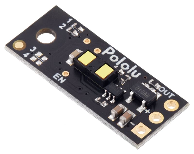
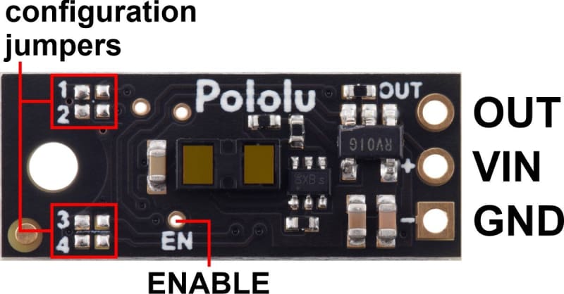
This small lidar-based distance sensor detects the presence of objects within 100 cm (39″). It has a single digital output that drives low when an object is being detected; otherwise, it is high. It works over an input voltage range of 3.0 V to 5.5 V, and the 0.1″ pin spacing makes it easy to use with standard solderless breadboards and 0.1″ perfboards.
This compact sensor is a great way to quickly detect the presence of nearby objects. As long as the sensor is enabled, it takes continuous distance measurements and uses a single digital output to indicate if it detects an object within its detection range. The output is driven low when the sensor detects an object; otherwise, the output is high.
Unlike simpler optical sensors that use the intensity of reflected light to detect objects, this sensor uses a short-range lidar module to precisely measure how long it takes for emitted pulses of infrared, eye-safe laser light to reach the nearest object and be reflected back. This allows the sensor performance to be largely independent of object reflectivity and ambient lighting conditions (though the range can be reduced for extremely low-reflectance objects).
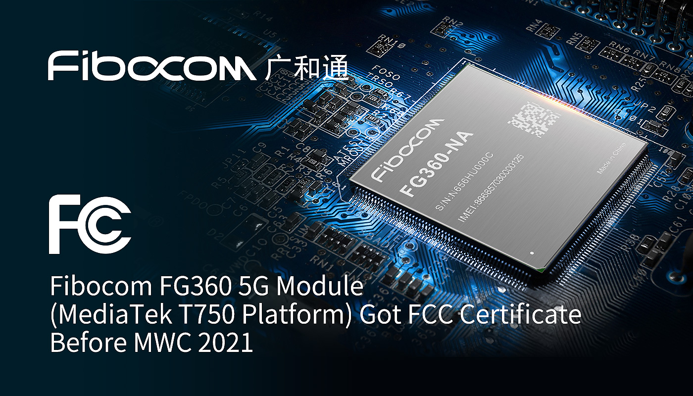
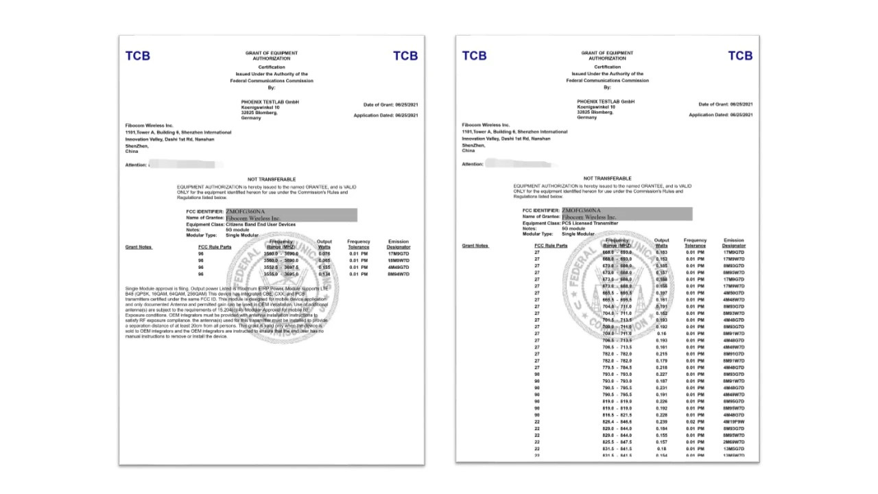
Fibocom (Stock Code: 300638), a leading global provider of IoT (Internet of Things) wireless solution and wireless communication modules, announces that its 5G wireless communication modules FG360-NA-03 has successfully certified by FCC (Federal Communications Commission) before Mobile World Congress (MWC) 2021. Fibocom’s FG360-NA is the first 5G module based on MediaTek T750 that received FCC certificate, which is significant for the module to officially march into the US market.
FCC certificate is an authoritative and mandatory certification for wireless communication products to be operated in the US. Completion of this certification indicates that Fibocom’s FG360-NA 5G module has reached the US network operation standard, which lays a foundation for FG360-NA to support multiple IoT applications in the US.
Based on the World’s 1st FWA CPE customized 5G SOC chipset, MediaTek T750, Fibocom’s FG360-NA module supports 5G NR Sub-6 band with up to 4.67 Gbps on the downlink and 1.25 Gbps on the uplink theoretically, enabling exciting 5G speed experience. It is worth noting that, integrated with MediaTek T750, the FG360-NA module has high integration and excellent performance that cover global main frequency band & ENDC (with NA and EAU Skus). Supporting 5G standalone network (SA) and non-standalone (NSA) network architectures, the module is also backward compatible with LTE/WCDMA network standards, which helps to reduce investment complexity in the initial stage of 5G construction.
Coming with a built-in quad-core & 2 GHz ARM Cortex-A55 CPU, Fibocom’s FG360-NA module supports 5G Sub-6GHz 2CC CA (Carrier Aggregation) 200MHz frequency to improve the utilization of spectrum resources and ensure an extended 5G coverage. In addition, supporting Wi-Fi 6 AX1800/ AX3600 (Main stream)/ AX4200/ AX6000 configuration, the FG360-NA module allows end devices to enjoy the full benefits of high-speed 5G + Wi-Fi 6 connectivity. The module also supports GNSS, including GPS, GLONASS, Beidou, Galileo and QZSS.
With a rich extension of interfaces including 2.5Gbps SGMII, USB 3.1/3.0/2.0, PCIe 3.0, GPIO, I2S, UIM and so on, the Fibocom FG360-NA 5G module seamlessly enables a wide range of IoT applications, providing high-speed experience for customers in the fields of FWA (Fixed Wireless Access), CPE, gateway, industrial monitoring, telemedicine, UAV, VR/AR, etc. Specially, the module supports full FWA software turnkey, realizing seamless plug-in and easy use.
“We are very excited to announce that our FG360-NA 5G module has certified by FCC”, said the director of Fibocom product management dept., “Fibocom’s FG360-NA is a 5G module with a quad-core & 2 GHz ARM Cortex-A55 CPU featuring with eMBB. Highly compatible with the MediaTek Wi-Fi MT7915 chipset, the FG360 5G module enables customers to design their products with the best performance and the most optimal cost in the application scenarios.”
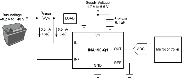
The INA190-Q1 is an automotive, low-power, voltage-output, current-shunt monitor (also called a current-sense amplifier). This device is commonly used for monitoring systems directly connected to an automotive 12-V battery. The INA190-Q1 can sense drops across shunts at common-mode voltages from –0.2 V to +40 V, independent of the supply voltage. In addition, the input pins have an absolute maximum voltage of 42 V.
The low input bias current of the device permits the use of larger current-sense resistors, thus providing accurate current measurements in the microamp range. The low offset voltage of the zero-drift architecture extends the dynamic range of the current measurement. This feature allows for smaller sense resistors with lower power loss, while still providing accurate current measurements.
Features
AEC-Q100 qualified for automotive applications:
Temperature grade 1: –40°C to +125°C, TA
Low input bias currents: 500 pA (typ)
(enables microamp current measurement)
Low power:
Low supply voltage, VS: 1.7 V to 5.5 V
Low quiescent current: 50 µA at 25°C (typ)
Accuracy:
Gain error: ±0.2% (A1 device)
Gain drift: 5 ppm/°C (max)
Offset voltage, VOS: ±15 µV (max)
Offset drift: 0.13 µV/°C (max)
Wide common-mode voltage: –0.2 V to +40 V with survivability up to 42 V
Bidirectional current sensing capability
Gain options:
INA190A1-Q1: 25 V/V
INA190A2-Q1: 50 V/V
INA190A3-Q1: 100 V/V
INA190A4-Q1: 200 V/V
INA190A5-Q1: 500 V/V
The INA190-Q1 operates from a single 1.7-V to 5.5-V power supply, and draws a maximum of 65 µA of supply current. Five fixed gain options are available: 25 V/V, 50 V/V, 100 V/V, 200 V/V, or 500 V/V. The device is specified over the operating temperature range of –40°C to +125°C, and offered in an SC70 package.
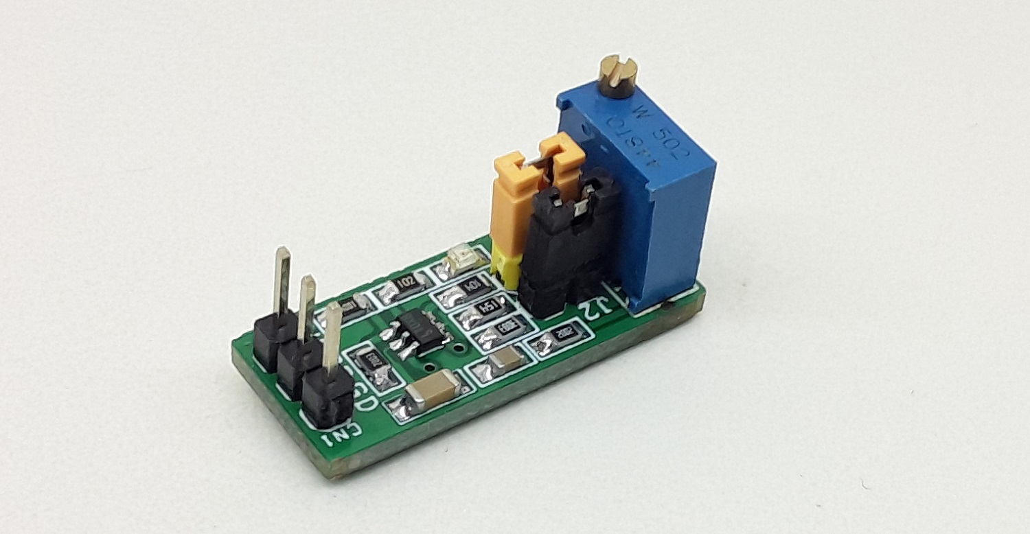
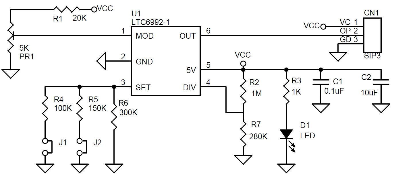
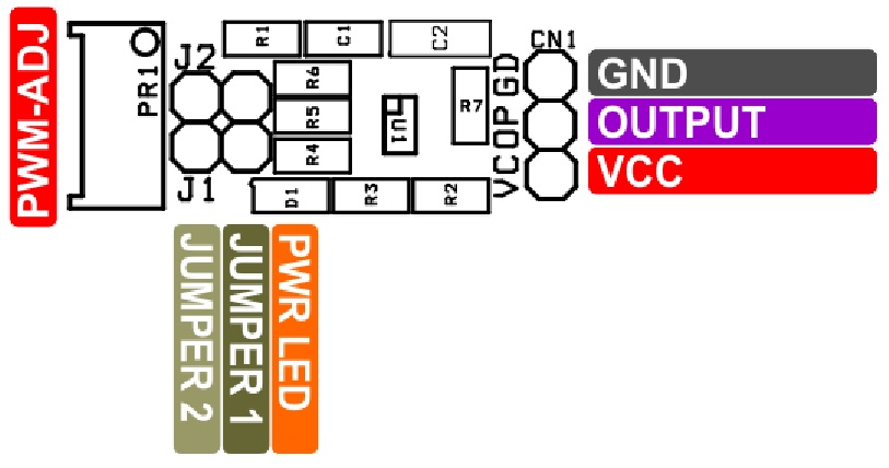
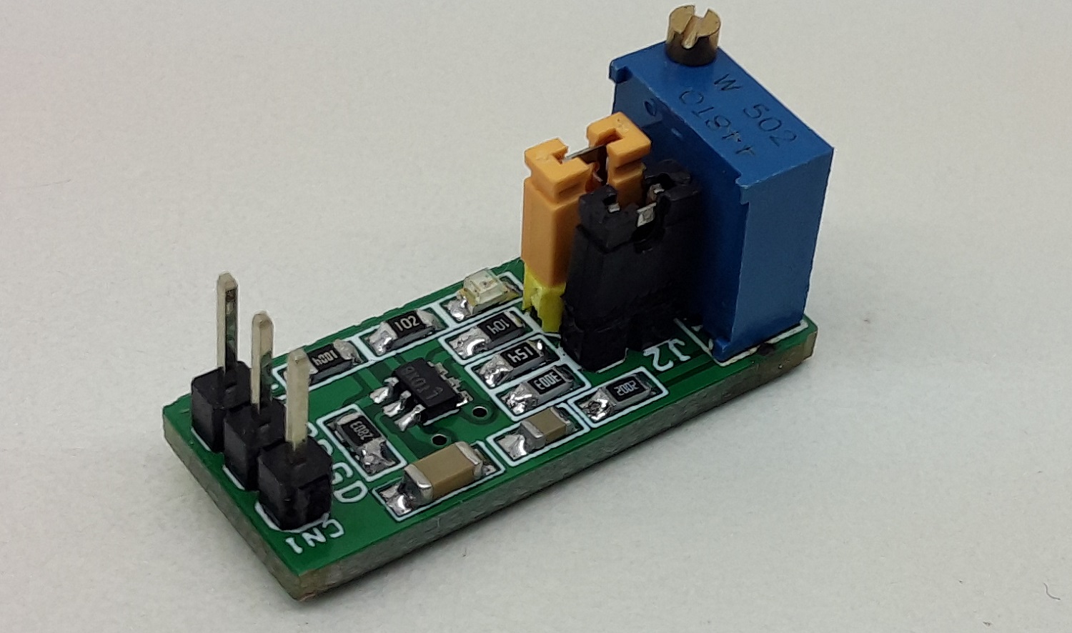
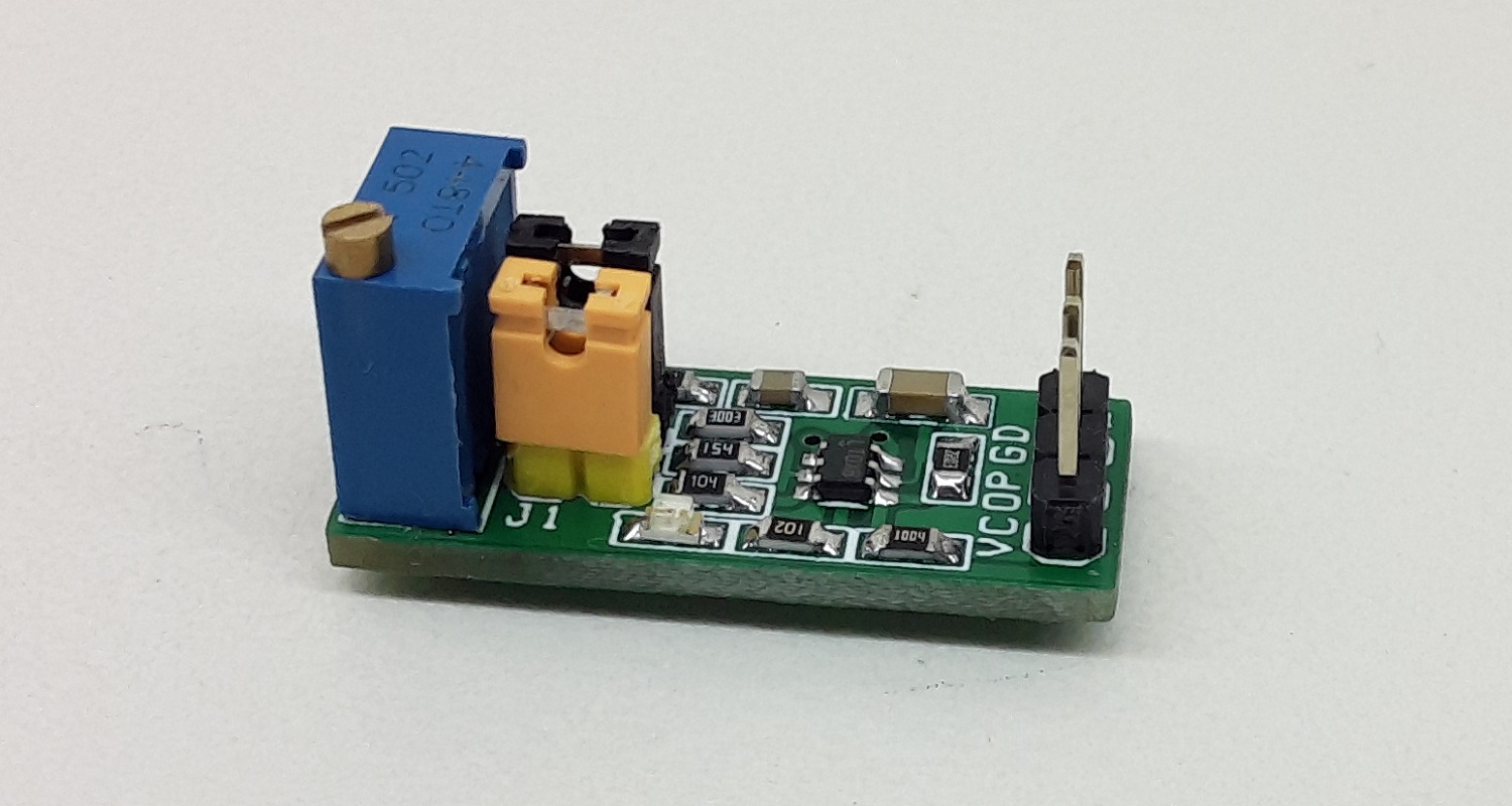
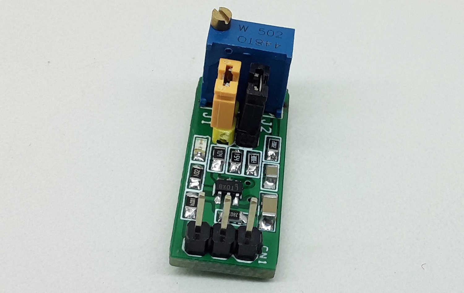
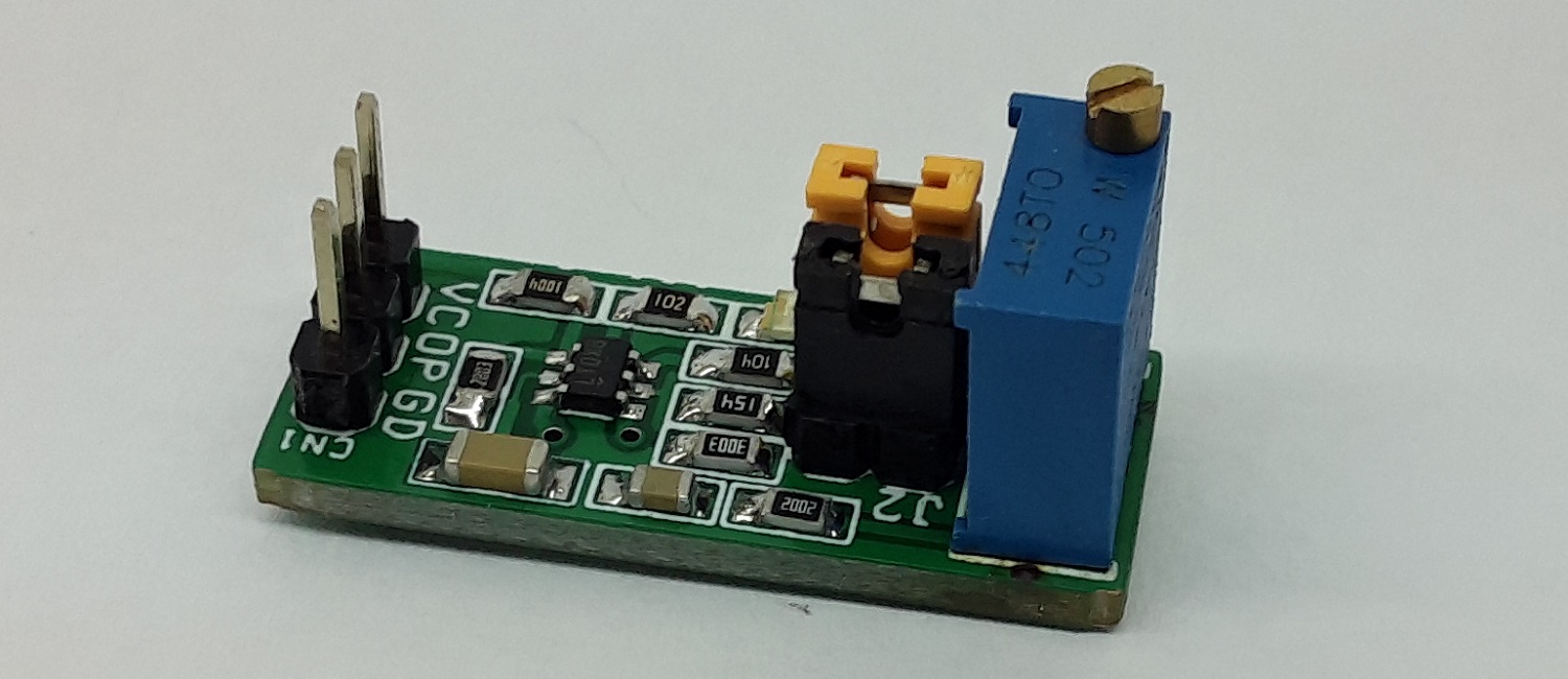
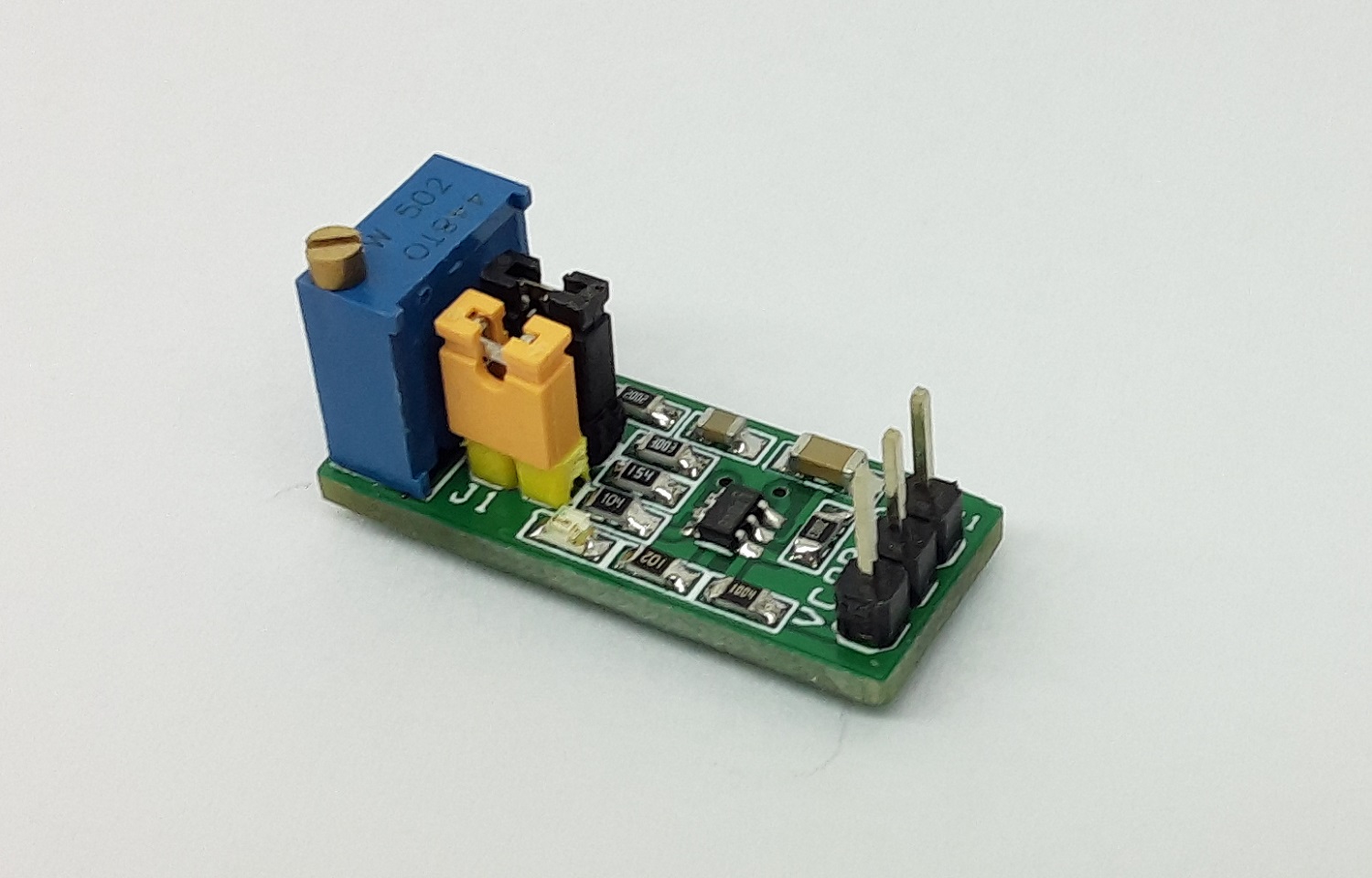
This is an easy-to-use voltage to PWM converter. The project occupies very little space. The circuit is built using the versatile silicon timing device LT6992-1 chip. Pulse Width Modulation (PWM) Controlled by Simple 0V to 1V Analog Input, multiturn trimmer potentiometer provided to adjust the duty cycle 0 to 100 %. The circuit also has provision to set the frequency to 2.65Khz, 7.8Khz, 10.7Khz or 15.7Khz using jumper J1 and J2. Circuit operates with a 5V Supply. D1 is a power LED, all connections are made easy using the 3 pin male header connector CN1. This is a very useful tool as test gear or to drive various circuits that require a PWM signal. The output frequency is very accurate and steady has 1.7% Maximum Frequency Error. CMOS Output Driver Sources/Sinks 20mA
Frequency Setting (Jumper J1 and J2)
J1-Open, J2 Open = 2.65KhZ
J1-Closed, J2-Open=10.4KHZ
J1-Closed, J2-Closed=15.7Khz
J1-Open, J2 Closed=7.8Khz
Duty Cycle: Duty Cycle is adjustable 0 to 100 % using Multiturn Trimmer Potentiometer PR1. The duty cycle can also be controlled using external analog voltage, remove PR1 and use GND pin and middle pin of trimmer pot, to apply 0 to 1V to output PWM 0 to 100%.
Power Input: Circuit operates with 5V DC power supply and consumes 10mA current
The diode clipper is an electronic circuit consisting of a diode(s) that clips or cuts off an input signal. The output of the clipping circuit depends on the diode orientation and input signal. Such a circuit is termed, Diode Clipper. The clipped-off signal produced at the output becomes flat when a certain voltage limit has reached and due to this it is also termed as Diode Limiter.
The half-wave rectifier is an example of a diode clipping circuit because when the diode is forward biased any voltage below zero is clipped off and, similarly, when the diode is reverse biased any voltage above zero is clipped off. It is eminent from this that the most common use of clipping circuits is in voltage protection and wave-shaping circuits. Especially, equipment requiring voltage to not exceed certain voltage levels such as from overvoltages, and spikes, etc. The conventional diodes, Zener diodes, and Schottky diodes can be used to alter the input signal.
Commonly, the conventional diodes and Schottky diodes are used in signal modifications and Zener diodes in voltage protection circuits.
Working Principle
It is known from previous articles that a conventional diode can be put to operate in forward or reverse bias conditions. In forward biasing, after a certain voltage drop (0.7V for Silicon & 0.3V for Germanium) the current starts flowing and the voltage drop across the diode remains constant (0.7V or 0.3V). Whereas, in reverse biasing, the diode does not conduct and the input signal is reflected across the diode unaltered. In simple words, for an ideal diode, it becomes short-circuited when forward biased and open-circuited when reverse-biased.
The input signal can have any form or shape that may be unidirectional or bidirectional depending on the circuit application. The sinusoidal signal, which is the most commonly used alternating (bidirectional) signal, is used to explain the diode clipping.
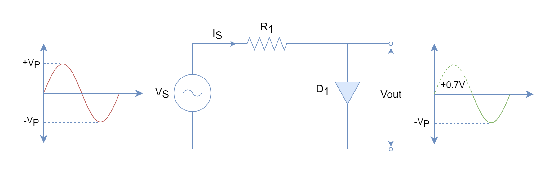
Positive Diode Clipping
The positive diode clipping circuit clips only the positive half-cycle of the input sinusoidal signal.
Figure 1: Positive diode clipping circuit
In the above figure, initially, the diode is not conducting (open) until the input voltage reaches around 0.7V during the positive half-cycle. Once, the diode starts conducting only a forward voltage drop appears across the diode irrespective of the input voltage magnitude. The positive half-cycle of the output wave depicts this with a flattened shape. During the negative half-cycle, the diode remains reverse-biased (open) and the whole input signal appears across the diode. Such a circuit only clip-off the input signal during the positive cycles i.e. any voltage above +0.7V will be clipped.
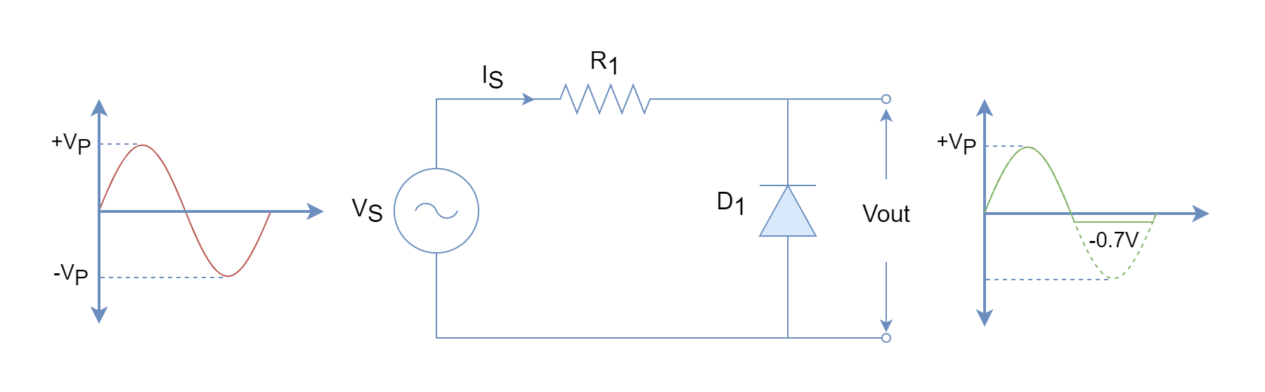
Negative Diode Clipping
In contrary to the positive diode clipping circuit, the following clipping circuit limits the voltage during the negative cycles only. The working principle is the same as described for the positive diode clipping circuit except the diode biasing is opposite. The negative clipping circuit limits negative voltage to -0.7V and any value less than this will be clipped off.
Figure 2: Negative diode clipping circuit
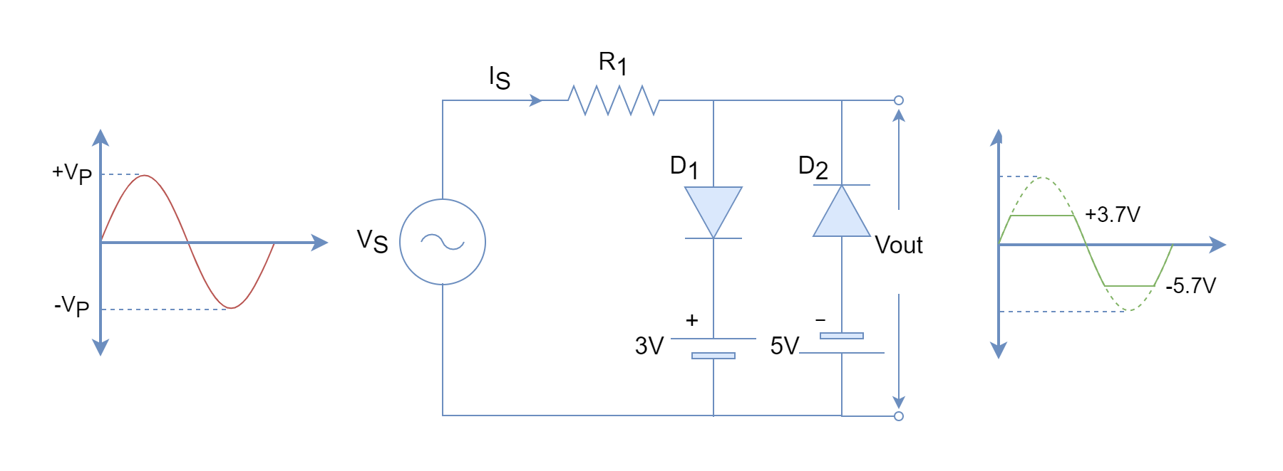
Positive & Negative Cycle Clipper
The combination of both positive and negative clipping circuits is a clipping circuit that limits voltage in both cycles. The diodes are placed in a reverse parallel arrangement and one of them conducts whilst the other remains open. During the positive half-cycle, the diode D1 conducts and D2 remains open. The reverse operation takes place during the negative cycle. The output waveform is limited to +0.7V during positive half-cycles and to -0.7V during negative half-cycles.
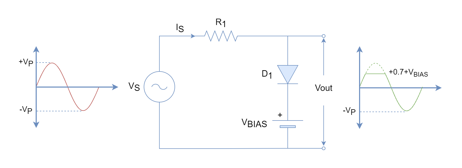
The voltage limitation produced by diode-only clipping circuits is limited to forward voltage drops. In order to increase limitation, a biasing voltage is used in series with the diode to increase the level of voltage where it starts conducting. In diode only positive cycle clippers, the cathode of the diode is at zero potential and a voltage of +0.7V at the anode is required to forward bias it. However, with the addition of biasing voltage such as an EMF battery in series with the diode, the cathode potential increases to VBIAS and now for forward biasing +0.7+VBIAS is required.
Positive Bias Diode Clipper
In the following figure, a positive bias diode clipper circuit is shown. This circuit limits any voltage above +0.7+VBIAS.
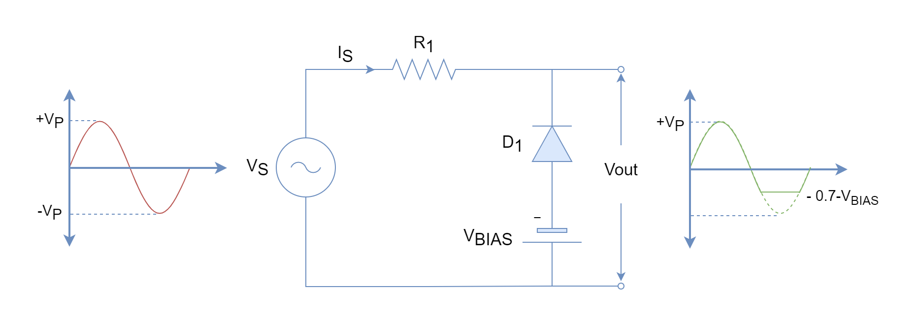
Negative Bias Diode Clipper
Similar to the positive bias diode clipper circuit, a biasing voltage in series with diode is added but in reverse polarity. The biasing aids the reverse biasing of the diode and an increased voltage is required to forward bias diode compared to the unbiased diode. Such a circuit limits any voltage below -0.7-VBIAS.
In order to clip both positive and negative cycles, the positive and negative bias diodes are combined. The bias voltage for each branch can be the same or different depending on the requirements or application of the clipping circuit. Moreover, a variable voltage clipper can be made by using a variable voltage source.
Figure 6: Positive and negative cycles bias-diode clipping circuit
In the above figure, different biasing voltages are used to illustrate the working during positive and negative cycles. The clipping occurs at +0.7+3=3.7V and -0.7-5=-5.7V for positive and negative cycles, respectively.
The output waveform of a very low amplitude signal is clipped to a large extent leading to the square waveform. Similarly, a high amplitude signal is clipped to a small extent, and at out a square wave is produced. The application of diode circuits is to eliminate noise, fluctuation, and spikes from the input signal.
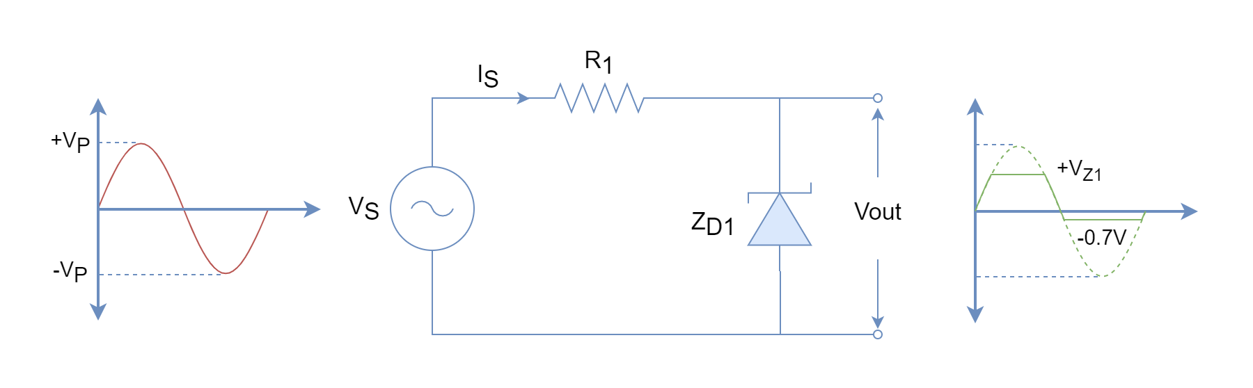
Zener Diode Clipper
A suitable clipper is one that can be designed to limit voltage accurately and with minimum components. The bias diode clipper requires biasing voltage which increases the effort and cost of the circuit. The requirement of biasing voltage can be avoided by using Zener diodes in clipping circuits. As described in the Zener Diode article, the Zener diode acts like a normal diode (0.7V forward voltage drop) when forward biased but in the reverse direction, it starts conducting above Zener voltage (VZ). The reverse current increases rapidly whilst the voltage across the Zener diode remains pretty constant. The rapid increase of Zener current requires a suitable series resistance to protect it from getting damaged.
In the following diagram, a Zener diode is used to clip both cycles. However, the negative cycle clipping is somewhat limited to the forward voltage drop. The Zener diode conducts below this forward voltage drop during negative cycles and above Zener voltage (VZ) during positive cycles.
In the following figure, a full-wave clipper based on two Zener diodes is shown. In this circuit, both cycles get limited to Zener voltages (VZ) of their respective Zener diodes. Simply, the ZD1 limits positive cycles, and ZD2 limits negative cycles to VZ1 and VZ2, respectively.
Figure 8: Positive and negative cycles Zener diode clipping circuit
The Zener diodes are available in a wide range having different Zener voltage levels and as such can be used in clipping circuits to obtain desired voltage limitations. The Zener diode-based clippers are mostly used in voltage protection circuits.
Conclusion
The clipping circuit limits or flattens the voltage at a certain level.
The clipping/shaping of the output waveform depends on the input signal and the circuit itself.
The clipping can be obtained for both cycles by the inclusion of two diodes.
The different clipping voltage levels can be obtained by using biasing voltages in series with the diodes.
The Zener diode can also be used in clipping circuits by operating it in the Zener breakdown region.
The Zener diode-based clipping circuit eliminates the use of diode biasing voltage.
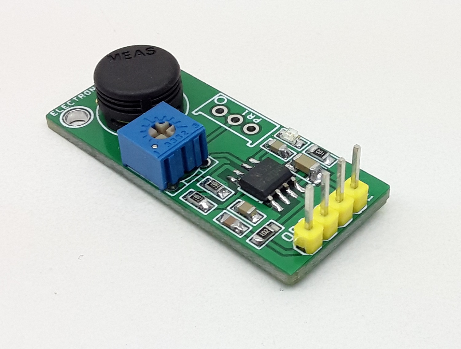
This sensor board provides frequency output as per relative humidity value. The project is based on a unique capacitive cell, this relative humidity sensor is designed for high volume, cost-sensitive applications such as office automation, automotive cabin air control, home appliances, and industrial process control systems. It is also useful in all applications where humidity compensation is needed. The circuit is built using a low-cost NE555 timer as an astable generator, humidity sensor MK1 acts as a variable capacitor and is connected to the TRIG and THRES pin. Pin 7 is used as a short circuit pin for resistor R3. The HS1101LF equivalent capacitor is charged through R2, R3, and PR1 is set the threshold voltage (approximately 0.67Vcc) and discharged through R2 only to the trigger level (approximately 0.33Vcc) since R3 is shortened to the ground by pin 7. Since the charge and discharge of the sensor run through two different resistors, R2 and R3, the duty cycle is determined by the following formulas.
Humidity Sensor – Humidity to Frequency Output – [Link]
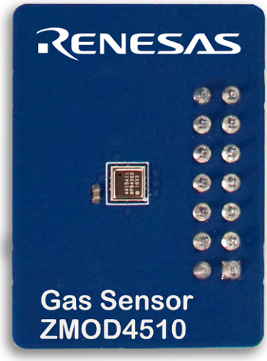
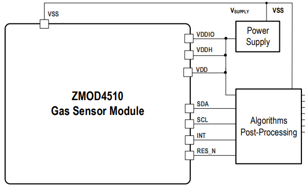
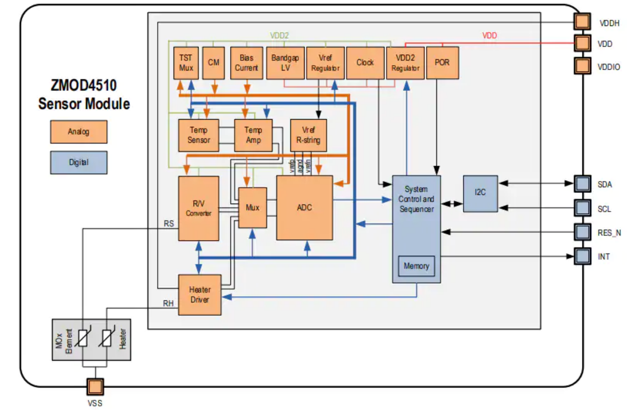
Renesas Electronics recently announced the expansion of its popular ZMOD4510 Outdoor Air Quality (OAQ) gas sensor platform with an IP67-qualifed waterproof package and a new AI-based algorithm that enables ultra-low power selective ozone measurements. The enhanced ZMOD4510 is the industry’s first fully calibrated, miniature digital OAQ sensor solution with selective ozone measurement capabilities, offering visibility into the air quality in users’ immediate environments for a personalized experience.
Ozone gas is a significant cause of poor outdoor air quality that poses health risks. Based on Renesas’ new ultra-low power firmware, the enhanced ZMOD4510 can detect specific ozone levels – without reporting on other pollutants – while maintaining power consumption under 200 uW. This selective measurement capability allows devices such as smart watches, phones, and smoke detectors to monitor for harmful ozone gasses typically found outdoors but which can drift indoors through open windows and doors. Optimizing the ZMOD4510 for very low power is key to enabling the longer life cycles required for these types of battery-powered devices.
“Measuring outdoor air quality really is about location, location, location, as levels can vary dramatically from street to street and even on opposite sides of the same street,” said Uwe Guenther, Senior Director, Sensing Solutions, IoT and Infrastructure Business Unit at Renesas. “The enhanced ZMOD4510 gives manufacturers the selective high-precision sensing, ultra-small size, and long battery life they need for battery-powered devices like smart watches and phones that offer customers a convenient and customized view of their immediate air quality environment.”
Renesas’ unique software-configurable ZMOD platform provides design flexibility for smart sensing systems, which allows firmware updates in the field to enable new, application-specific capabilities such as selective ozone detection.
The ZMOD4510’s ability to quantify selective Ozone levels in concentrations as low as 20 parts per billion (ppb) coupled with its low power, small size and outstanding flexibility makes it an ideal solution for mobile and wearable devices, as well as industrial applications such as wireless security cameras and parking meters.
Features
Sensor output based on operation method:
Non-selective measurement of nitrogen dioxide (NO2) and ozone (O3)
Selective ozone (O3) measurement using ultra-low power
Supports international standards for air quality, such as the US Environmental Protection Agency (EPA)
Ultra-low average power consumption down to 0.2mW
External reset pin (active-LOW)
Siloxane resistant
RoHS compliant
Target operation temperature: -40 °C to +65 °C
Supply voltage: 1.7V to 3.6V
Water and dustproof version available (IP67 certified)
Available assembly sizes:
3.0mm x 3.0mm x 0.7mm (standard version)
3.0mm x 3.0mm x 0.9mm (IP67 version)
The new waterproof packaging allows the sensor to operate in harsh and submersible environments. The IP67-rated sensor maintains superior accuracy and high performance while eliminating the need for expensive waterproofing systems – all in a tiny 3mm x 3mm x 0.9mm LGA package. The sensor is shipped fully calibrated in the hydrophobic and oleophobic package, and customers can apply a conformal coating on their circuitry rather than adding an external membrane to the module.
Renesas has identified and created Winning Combination system architectures for a variety of applications where the ZMOD4510 family of products adds differentiative value in the system. For example, a new winning combination for smart lighting, “Building Automation Lighting with Air Quality Sensors Solution,” demonstrates a use case in building automation. The ZMOD4510 sensors also add another dimension to wearables such as watches. Made from mutually compatible devices that work together seamlessly, Renesas’ Winning Combinations are vetted solutions engineered to help customers accelerate designs and get to market faster. Renesas offers over 200 Winning Combinations that can be found at renesas.com/win
The ZMOD4510 is calibrated to the U.S. Environmental Agency’s (EPA) Air Quality Index for measuring ozone, and is highly resistant to siloxanes, enabling exceptional reliability for use in harsh environments.
The enhanced ZMOD4510 platform is available now in both a standard and IP67-rated sensor package. For more information, please visit www.renesas.com/zmod4510.
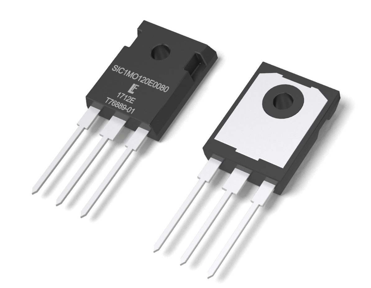
Littelfuse offers enhancement-mode N-channel SiC MOSFET, LSIC1MO series
SiC MOSFETs from IXYS: A Littelfuse Technology offer an exceptional alternative to traditional Si-based power transistor devices. The MOSFET device structure enables lower per-cycle switching losses and improved light load efficiency when compared to similarly rated IGBTs. Inherent material properties allow the SiC MOSFET to outclass its Si MOSFET counterparts in blocking voltage, specific on-resistance, and junction capacitances. The robust design of these SiC MOSFETs accommodate a wider range of high-temperature applications. Higher switching frequencies enable smaller passive filter components; lower device losses enable smaller heat sinks. Combined, these features enable improved system efficiency and power density. The devices have smaller die sizes per voltage/current rating making them ideal for motor drive control, power conversion systems, solar inverters, and other applications.
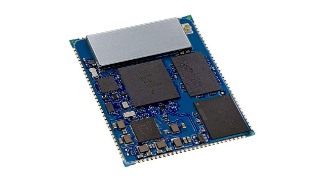
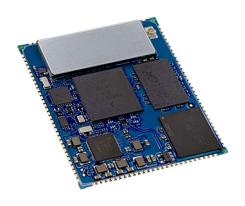
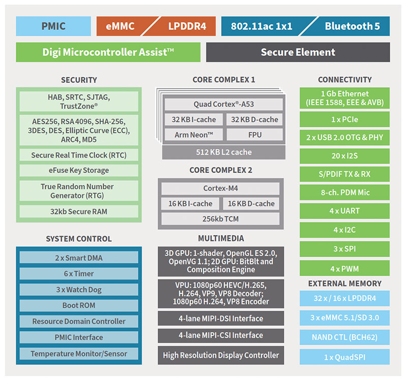
Digi International Inc. has been manufacturing M2M and IoT devices from radio frequency modems to gateways, cellular routers, networking devices, embedded system-on-modules (SOM) and single-board computers (SBCs) that have been used for several use cases. A new addition to its long list of SOMs, Digi ConnectCore 8M Mini SOM is designed on the NXP i.MX 8M Mini application processor as a secure integrated system-on-module (SOM) platform.
With the increasing demand for SOM for industrial IoT applications, this Digi ConnectCore 8M Mini comes with a built-in Graphics Processing Unit (GPU) having GCNanoUltra for 3D acceleration, GC320 for 2D acceleration. The SOM also supports 1080 p 60 fps display through MIPI DSI that can be interfaced to collect and process the data that can be displayed. The VPU supports 1080 p 60 HEVC H.265 (decode), VP9, H.264, VP8 (encode/decode). All the predecessor to this SOM including the Digi ConnectCore 8M Nano does not come with the built-in video processing unit.
“Digi ConnectCore 8M Mini features four power-efficient Arm® Cortex®-A53 cores, one Cortex-M4 core, and the Digi Microcontroller Assist Cortex-M0, which allow it to minimize power consumption while maintaining a high standard of performance.”
Features of Digi ConnectCore 8M Mini SOM
Application Processor: NXP i.MX8 Mini processor integrated with four Cortex-A53 cores @1.6 GHz and Cortex-M4 400 MHz core processor
Memory: up to 2 GB of LPDDR4 (32-bit)
Storage: Up to 8 GB eMMC
Wireless Connectivity: IEEE 802.11a/b/g/n/ac dual-band wireless and Bluetooth 5
Interfaces/Peripherals: USB 2.0 OTG controllers with integrated PHY interfaces, 3x Ultra Secure Digital Host Controller (uSDHC) interfaces, Gigabit Ethernet controller, 4x UART modules, 4x I2C modules, 3x SPI modules, and PCI Express 2.0
Operating Temperature: Industrial: -40° C to 85° C
Dimensions: 40 mm x 45 mm x 3.5 mm
The 64-bit processor architecture has 4 cores with an integrated RAM of up to 2 GB LPDDR4 and Up to 8GB eMMC flash storage. The Digi ConnectCore 8M Mini SOM also supports wireless communication protocols including Wi-Fi 802.11a/b/g/n/ac and Bluetooth 5. With IEEE 802.11ac, the SOM is a powerful device for applications that require wireless transmission for long-distance and high data rates. It comes with similar ethernet connectivity as the 8M Nano SOM with 10/100/1000M Ethernet + AVB.
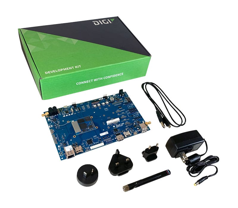
One of the key highlights of this SOM is the support for the Android operating system and for low-power processing, it features Cortex-M4 400 MHz core processor. With the small form factor, the SOM comes with a rich set of interfaces that includes 4x UART, 4x I2C, 3x SPI, and PCIe 2.0. The SOM is also marketed as the Digi ConnectCore 8M Mini Development Kit that comes with console port cable, dual-band antenna, power supply and accessories, and reference designs for LVDS, HDMI and CAN-FD other than the SOM.
For more information about the product, head to the official product page. To buy this product, you can contact the manufacturer through call or find a local distributor.