Crowd Supply ITACA Innovation uChip Microcontroller Board

Crowd Supply ITACA Innovation uChip Microcontroller Board is an Arduino Zero-compatible, narrow DIP-sized USB board. Based on the Microchip Technology SAM D21 Arm® Cortex®-M0+ Microcontroller, the uChip integrates 500mA boost and 1A buck converters and 14 I/O pins, two of which can be used for SWD programming and debugging. The tiny uChip can fit into a standard 0.3″ 16-DIP socket or plug directly into a breadboard, making it easy to integrate into any application.

The Crowd Supply ITACA Innovation uChip can easily be programmed using  BASIC, C/C++, asm, or CircuitPython.

With plenty of communication peripherals, low stand-by/run current consumption (270µA in standby when powered externally), and a compact size, uChip is ideal for IoT and battery-powered applications.

Features

  • Microchip Technology ATSAMD21 MCU
    • 48MHz Arm Cortex M0+
    • 256KB flash (248KB free due to integrated bootloader)
    • 32KB RAM with zero wait states
  • I/O via 2x 8-pin headers with 2.54mm pitch, 7.62mm (0.3″) row spacing
    • 14x I/O pins including two that can be used to connect an external SWD programmer/debugger
      • 7x 12-bit ADC inputs
      • 10-bit DAC output
      • 14x external interrupt input pins
      • Up to 5x serial interfaces using SPI, I2C, or UART
      • I2S port for audio decoders
      • Up to 13x PWM pins.
    • 2x power pins (VCC and GND)
  • Programmable status LED
  • Multi function push button for reset/program.
  • Power supply
    • 5.0V via micro USB port, or 3.3V to 5.0V via pin
    • Integrated 500mA boost and 1A buck converters
    • Automatic power switching circuitry
  •  Form-factor
    • 28.5mm x 10.16mm including USB
    • 27.23mm x 10.16mm excluding USB
    • 4-layer PCB for improved noise performance

Video

more information: https://www.kickstarter.com/projects/1186620431/uchip-arduino-zero-compatible-in-a-narrow-dip-16-p?ref=749984&token=7dfa566d

RadSens module: An ultracompact Arduino Dosimeter

A dosimeter is an extensively used device for measuring ionizing radiation. Modern electronic personal dosimeters can be worn by a person to monitor the dose of radiation received. These modern dosimeters can give a continuous readout of cumulative dose and current dose rate and can warn the wearer with an audible alarm when a specified dose rate or a cumulative dose is exceeded. Electronic personal dosimeters are the most common type. They use LEDs or LCDs to display the radiation intensity, allow alarm warnings at preset levels, record accumulated dose, and can be reset after taking a reading for record purposes.

The RadSens module, designed by ClimateGuard, is an ultracompact Arduino dosimeter. It serves as a radiometer and dosimeter based on the tried and tested gas-discharge Geiger-Muller counter SBM 20-1. The iconic SMB20-1 tube is a standard testing element in many DIY and professional Geiger counters. It is sensitive to beta and gamma radiation. These tubes operate from 350 to 475 V DC for which an onboard 400V voltage generator is employed. The RadSens module, additionally, supports different gas-discharge Geiger-Muller counters (like J305, M4011, STS-5, or others with anode voltage between 380 – 440 volts.). The tube can be changed and soldered directly through holes in the board.

At the core of the dosimeter is an STM32 microcontroller. The data received from the Geiger counter tube is transmitted via the I2C interface. Fine-tuning of the counter sensitivity is also supported. The RadSens module can work as a standalone device where the module acts as a simple indicator. The flashing intensity of the built-in LED indicates how high the radiation level is. With an increase in radiation, the blinking frequency will increase proportionally and vice versa.

It can also work as a part of an external Arduino, STM, Raspberry microcontroller, or as part of your device. To run the board one can use the sketch example or their libraries on GITHUB.

The RadSens board generates three values: radiation intensity with an averaging algorithm for accurate measurement of radiation over a long period (500s), radiation intensity with an algorithm with a dynamic range of calculation time for registering local sources of pollution, and the number of registered impulses since the last request to the I2C. Impulse registration, calculation algorithms, and data transmission via I2C with a frequency up to 400kHz are all implemented on the MCU installed on the board. The sensor works in the slave mode, and the description of registers is available here.

Source: https://www.tindie.com/products/climateguard/dosimeter-with-i2c-radsens-arduino/

The board measures only 89 х 21 х 16 mm. The supply voltage can be in the range of 3.0V to 3.5V. The maximum current consumption at high radiation is no more than 50mA. For reducing the power consumption, the device supports changing the I2C address and turning off the high voltage generator (400V).

RadSens module Tindie page: https://www.tindie.com/products/climateguard/dosimeter-with-i2c-radsens-arduino/

Active Rectifier Controller with Reverse Protection for Battery and Solar cell

This demonstration circuit is an active rectifier with reverse protection for batteries in automotive applications. The project is designed for 5A load current. Two clamping diodes, D1 and D2, are used on the board to protect the IC from overvoltage spikes at the input. The input supply range is 12V to 24V.  The active rectifier controller chip LT8672 controls an external N-channel MOSFET (Q1) to form an ideal diode. The GATE amplifier senses across DRAIN and SOURCE and drives the gate of the MOSFET to regulate the forward voltage to 20mV. As the load current increases, GATE is driven higher until a point is reached where the MOSFET is fully on. If the load current is reduced, the GATE amplifier drives the MOSFET gate lower to maintain a 20mV drop. If the voltage VDRAIN is reduced to a point where a forward drop of 20mV cannot be supported, the GATE amplifier drives the MOSFET off.

Active Rectifier Controller with Reverse Protection for Battery and Solar cell – [Link]

Pimoroni PGA2040: A Compact RP2040-based Breakout Board

Already, there have been a bunch of tiny RP2040-based development boards in the market. However, due to its small size and high performance, the Raspberry Pi in-house tape out of $1.00 RP2040 MCU has increased the demand in order to manufacture compact boards. As the name suggests, the Pimoroni PGA2040 breakout board comes in the form of a pin grid array of size 21x21x3mm.

Recently, Raspberry Pi announced that designers can now buy the RP2040 SoC for $1.00 and design their development board. In the market for smart cities and automation, we need tiny boards that can aid several space-constrained applications. With the dual Cortex M0+ processor cores clocked up to 133 MHz frequency, backed up by six banks of 264KB, embedded SRAM has the distinctive features of programmable IOs.

PGA2040 Breakout Board

Pimoroni says:

“PGA2040 is a compact RP2040 breakout intended for the most svelte and embeddable of projects. It contains only the components necessary to run the RP2040 (that’s the crystal, flash, regulator and essential support circuits), and it has no fripperies like LEDs, buttons and USB connectors – you’ll need to attach your USB connector to be able to program it.”

Even with such a small footprint, the Pimoroni PGA2040 has 30 GPIO pins signifying four more than the Raspberry Pi Pico and 4 are ADC equipped. However, please note that header pins are sold separately. If you are interested in soldering, you can buy the standard Pico pin headers or add some extra cost and get the aesthetic-looking custom PGA pin header and socket, priced at £4.50 but is not yet available in the Pimoroni store. The manufacturer notes that these custom PGA pin headers will “turn PGA2040 into a full faux-retro 486-era device” for your use case.

How to get started with PGA2040
Image Credit: Open Cloudware

Just like the Raspberry Pi Pico and other RP2040-based boards, this also supports C++, MicroPython or CircuitPython. If you have played with any of these boards, it won’t be difficult for you. But in case you are new to the ecosystem, please visit the RP2040 page. You can find more details on how to get started with Pimoroni PGA2040 using CircuitPython on the PGA2040 product page. The hardware is in stock and up for sale priced at £6.90.

STM32 IoT Discovery Kit for Cellular Applications: B-L462E-CELL1

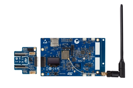
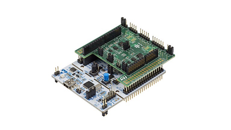
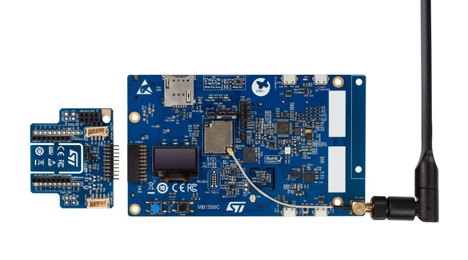
The STM32 IoT Discovery Kit, commonly known as B-L462E-CELL1, is a ready-to-use development platform for cellular IoT devices created by STMicroelectronics.

According to ST, the Discovery kit integrates a discovery mainboard powered by an LBAD0ZZ1SE module, a global coverage antenna, and a fan-out board. This module also delivers class-leading optimization and flexibility in a highly integrated package, making it ideal for embedded developers and IoT evangelists.

Technical Specifications of STM32 IoT Discovery Kit

  • Ultra-low-power STM32L4 Series STM32L462REY6TR microcontroller based on the Arm Cortex-M4 core with 512 Kbytes of Flash memory and 160 Kbytes of RAM in a WLCSP64 package.
  • 64 Mbytes of onboard Quad-SPI Flash memory from Micron is exclusive with the 1 MByte of Quad-SPI Flash memory inside the module.
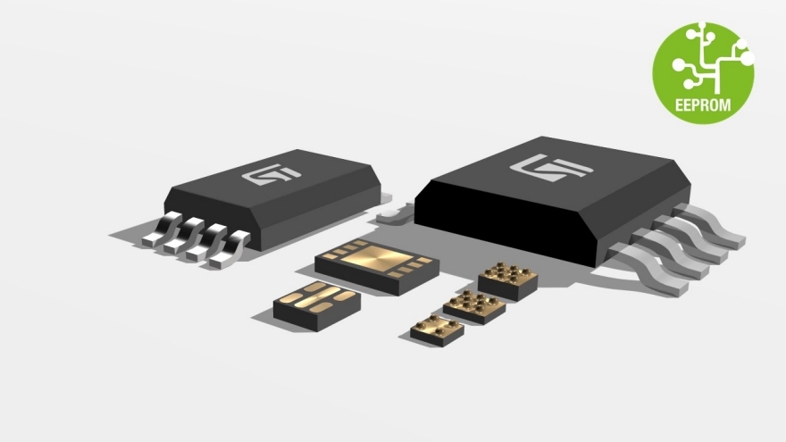
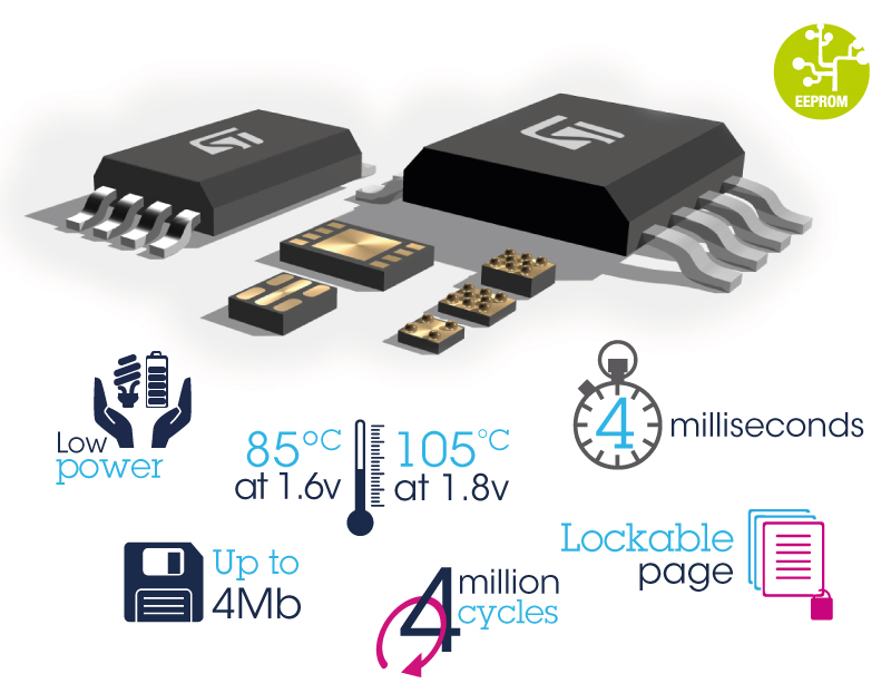
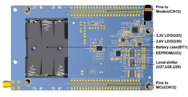
  • 16 Kbytes of I2C EEPROM (M24128-DFMN6TP) from STMicroelectronics.
  • 0.96-inch 128 x 64 OLED screen with SPI interface.
  • Low-power Audio CODEC with PCM bus and I2C interface.
  • Flexible power-supply options: ST-LINK USB, User USB, UART USB, Power USB, or three AAA batteries.
  • On-board ST-LINK/V2-1 debugger/programmer with USB re-enumeration capability: mass storage, Virtual COM port, and debug port.
  • End-to-end connectivity applications.
  • Low‑power cellular network services from Truphone.
  • Support of a wide choice of Integrated Development Environments (IDEs) including IAR Embedded Workbench, MDK-ARM, and STM32CubeIDE.

Labeled STM32 IoT Discovery Kit

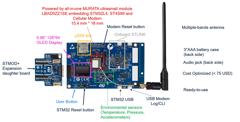
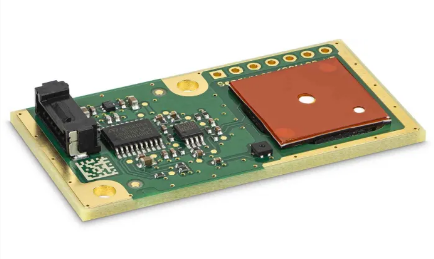
The Discovery kit comes with an LBAD0ZZ1SE module featuring an ultra-low-power STM32L462RE microcontroller at its heart. This cellular module from Murata is conveniently powered via the STM32L4.

With ST’s ultra-low-power technologies in the STM32L4, which draws about 2µA in STOP 2 mode, and a cellular chipset drawing less than 1.4µA in Power Saving Mode (PSM), the B-L462E-CELL1 Discovery kit provides a platform to develop equipment with a battery life of up to 10-years for smart-city, smart-industry, smart-agriculture, smart-metering, and wearable applications

The LBAD0ZZ1SE module also comes with a built-in ST4SIM-200M GSMA-certified embedded SIM (eSIM) which is pre-programmed via a bootstrap connectivity profile from Truphone, an ST Authorized Partner. The eSIM enables the quick development of power-conscious Cellular IoT devices that connect to the Internet through LTE-Cat M and NB-IoT networks.

In addition, the eSIM is GSMA SGP.02 v3.2 certified and offers strong resistance to cellular connectivity attacks, providing enhanced cyber-security protection. The ST4SIM-200M embedded SIM is compatible with 2G, 3G, and 4G (LTE) networks, as well as CDMA, NB-IoT, and CAT–M. Moreover, the kit focuses on applications that require wireless connectivity, and it also supports Over-the-Air updates with this SIM. This allows it to be more portable as it won’t rely on Wi-Fi hotspots for IoT applications.

Top View STM32 IoT Discovery Kit

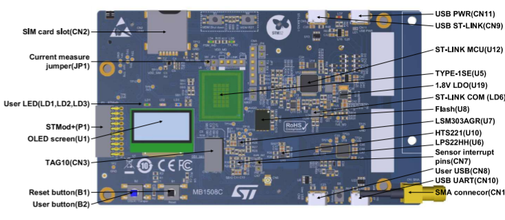
The manufacturer has also provided several sensors, including ultra-low-power LSM303AGR 3D-accelerometer-magnetometer, a capacitive digital sensor for relative humidity and temperature (HTS221), and an LPS22HH pressure sensor. So, the kit facilitates the development of motion and environmental monitoring solutions, with this set of onboard sensors. The board is activated instantly by connecting it to a power source via ST-LINK USB, User USB, UART USB, Power USB, or three AAA batteries.

Connectors Included with Board

  • SMA antenna connector
  • Two 50-pin 2.54 mm pitch headers
  • STMod+
  • micro-SIM card slot
  • 3.5 mm CTIA stereo headset jack including analog microphone input
  • USB Micro-B connectors for power, USARTs, USB device, and ST-LINK/V2-1
  • TAG10
  • mikroBUS expansion connectors
  • ESP‑01 expansion connector
  • Grove Seeed Studio breadboard, I2C, and UART expansion connectors

Discussing further, the kit also features the MAX9867ETJ+, an ultra-low power stereo audio codec, designed for portable consumer devices. Adding more of the hardware, there are three user LEDs and two pushbuttons (user and reset).

The software ecosystem includes an ST-LINK debugger/programmer and a comprehensive STM32Cube software library to demonstrate end-to-end communication. The kit includes a variety of IDEs, like IAR Embedded Workbench, MDK-ARM, and STM32CubeIDE. The X-CUBE-CELLULAR, a STM32Cube software expansion package, controls the Discovery kit. It also provides support for the Berkeley (BSD) sockets application programming interface (API). Hence, users may connect their prototypes to the Internet using BSD’s standardized function calls. This is used for Internet communication, eliminating the requirement to develop an AT-command driver to control the modem.

Bottom View STM32 IoT Discovery Kit

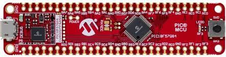
We also saw the STM32 Nucleo-64 development board, which provides flexible prototyping due to its support for Arduino Uno headers; however, this STM32 Cellular IoT Discovery kit received an upgrade to many additional components, including a display, onboard sensors, and LEDs. For those looking for some fast prototyping, a Nucleo board is a good option otherwise, B-L462E-CELL1 will suffice.

The STM32 B-L462E-CELL1 Cellular IoT Development Kit is available at $74 on the official product page.

PIC18F-Q84 Family of Microcontrollers

Microchip’s PIC18-Q84 8-bit PIC® MCUs with an extensive array of CIPs and CAN FD

The PIC18-Q84 family of microcontrollers (MCUs) from Microchip Technology expands the 8-bit PIC MCUs by combining an extensive array of CIPs with controller area network flexible data rate (CAN FD). These MCUs contain time-saving CIPs in up to 48-pins with up to 128 KB of Flash memory. The family offers increased flexibility with customizable timers and automated analog signal analysis for real-time response. Additionally, they include industry-standard features like the JTAG boundary scan, 32-bit cyclic redundancy check (CRC) with memory scan on boot for added system safety. Users can benefit greatly from the saved time since it is significantly easier to configure a hardware-based peripheral instead of writing and validating an entire software routine to accomplish a task.

Features

  • CAN FD module
  • Supports data bit rate up to 10 Mbps
  • Backward compatible to support: CAN 2.0A, 2.0B
  • Meets ISO11898-1:2015
  • Direct memory access (DMA)
  • Controller eliminates the need for CPU involvement in data transfers
  • I2C and SPI
  • Improves system performance and reduces power consumption
  • Vectored interrupts (VI)
  • Provides faster response times with fixed latency reducing software overhead
  • Serial communications
  • UART with support for asynchronous, DMX, DALI, and LIN

Critical Safety

  • Functional safety ready
  • 32-bit cyclic redundancy check with memory scan (CRC/SCAN)
  • Ensure the integrity of the memory with scan on boot
  • Windowed watchdog timer (WWDT)
  • JTAG boundary scan – addresses assembly circuit complexity

more information: http://ww1.microchip.com/downloads/en/DeviceDoc/30010228A.pdf

M95M04-DR – 4-Mbit serial SPI bus EEPROM

The M95M04-DR device is electrically erasable programmable memory (EEPROM) organized as 524288 x 8 bits, accessed through the SPI bus. The M95M04-DR can operate with a supply range from 1.8 to 5.5 V, and is guaranteed over the -40 °C/+85 °C temperature range.

Flexible and intensive datalog function is also facilitated with 4Million erase/write cycles per byte.

The SPI bus signals are C, D and Q, as shown in Figure 1 and Table 1 in the datasheet (see Related Documents on the right). The device is selected when Chip select (S) is driven low. Communications with the device can be interrupted when the HOLD is driven low.

Features

  • Compatible with the serial peripheral interface (SPI) bus
  • Memory array
    • 4 Mbit (512 Kbytes) of EEPROM
    • Page size: 512 bytes
    • Additional write lockable page (identification page)
  • Write time
    • Byte write within 5 ms
    • Page write within 5 ms
  • Write protect
    • quarter array
    • half array
    • whole memory array
  • Max clock frequency:
    • 10 MHz for VCC ≥ 2.5 V
    • 5 MHz for VCC ≥ 1.8 V
  • Single supply voltage: 1.8 V to 5.5 V
  • Operating temperature range: from -40 °C up to +85 °C
  • Enhanced ESD protection (up to 4 kV in human body model)
  • More than 4 million write cycles
  • More than 40-year data retention
  • Packages
    • SO8N (ECOPACK2)
    • TSSOP8 (ECOPACK2)
    • WLCSP (ECOPACK2)

X-NUCLEO-EEPRMA2 – Standard I²C and SPI EEPROM memory expansion board based on M24xx and M95xx series for STM32 Nucleo

The X-NUCLEO-EEPRMA2 expansion board is designed for M24xx series I²C and M95xx series SPI EEPROM for data reading and writing. The expansion board acts as an external storage device that can be used to store data such as manufacturing traceability, calibration, user settings, error flags, data logs and monitoring data to make applications more flexible and accurate.

The X-NUCLEO-EEPRMA2 expansion board is compatible with the Arduino UNO R3 connector pin assignment and can be easily plugged to any STM32 Nucleo development board. You can mount the ST morpho connectors if required.

Features

  • Up to 1-Mbit serial I²C bus embedded EEPROM
  • Up to 4-Mbit SPI bus embedded EEPROM
  • Easy portability across different MCU families
  • Equipped with Arduino™ UNO R3 connector
  • Compatible with STM32 Nucleo boards
  • Free comprehensive development firmware library and sample implementation available when the X-NUCLEO-EEPRMA2 expansion board is plugged on top of a NUCLEO-F401RE or NUCLEO-L053R8 development board
  • Developer can choose and solder an EEPROM to be tested using the evaluation software provided

more information: https://www.st.com/content/ccc/resource/sales_and_marketing/presentation/product_presentation/group0/f4/3e/88/b1/ec/65/40/3b/Wolrd_first_4Mbit_SPI_EEPROM_presentation/files/Wolrd_first_4Mbit_SPI_EEPROM_presentation.pdf/jcr:content/translations/en.Wolrd_first_4Mbit_SPI_EEPROM_presentation.pdf

Sensirion SFA30-D-T is a formaldehyde detection module

Formaldehyde Sensor Module for HVAC and Indoor Air Quality Applications

SFA30 is a formaldehyde detection module based on electrochemical sensing technology optimized for lowest false alarm rates. The SFA30 HCHO sensor has alow cross-sensitivity to ethanol and is optimized to operate in the low parts-per-billion (ppb)range to accurately detect low HCHO concentrations around the WHO reference value for rindoor exposure. Temperature and humidity compensation via an integrated Sensirion RHT sensor and an integrated microprocessor ensures reliable performance in changing indoor environments. The sensor can withstand adverse environmental conditions during storage, handling, and transportation.The robust sensor has a lifetime of 6 years due to its advanced anti-dry technology. Each SFA30 is factory-calibrated and can be easily integrated via I2C or UART interface into your device. The low power consumption allows for battery operation. This makes SFA30 a reliable, easy-to-use, and high-quality HCHO&RHT combo sensing solution.

Target applications

  • Real-time reading of HCHO gas concentration in parts per billion
  • Air Conditioners and Air Exchangers
  • Air Purifiers
  • Indoor Air Quality Monitors

Key features

  • Lowcross-sensitivity to ethanol
  • Long-term stability and 6 years’ service life time
  • Patented electrochemical cell with anti-dry technology
  • I2C/UART interface with lifetime-calibrated output
  • Fully temperature and humidity compensated via Sensirion RHT sensor

more information: https://www.sensirion.com/en/

Texas Instruments Announces Ultra-Thin, 1.2-V to 1.8-V Supply, High Accuracy Digital Temperature Sensor with I2C Interface

Texas Instruments has announced the high-precision temperature sensor TMP114 with an I2C-compatible digital output in an ultra-thin (0.15 mm) 4-pin package. With a low height package, the TMP114 can be put under surface mount components for the fastest and most accurate temperature measurement and supports the latest thin form factor systems.

The TMP114 has an accuracy of ±0.3 °C and offers an on-chip 16-bit analog-to-digital converter (ADC) that provides a temperature resolution of 0.0078 °C.

Internal Diagram

The TMP114 is designed to operate from a supply voltage range of 1.08 V to 1.98 V, with a low average supply current of less than 0.7 μA. The low supply support, along with extremely low power consumption, is designed for battery-powered applications. The TMP114 is 100% tested on a production setup that is NIST traceable.

Features

  • High Accuracy
    • ±0.3 °C maximum from –10 °C to +85 °C
    • ±0.5 °C maximum from –40 °C to +125 °C
    • ±0.1 °C typical
  • Operating Temperature Range: –40 °C to +125 °C
  • 16-bit Resolution: 0.0078 °C (LSB)
  • Low Power Consumption:
    • 0.7-μA Average Supply Current
    • 0.16-μA Shutdown Current
  • Supply Range of 1.08 V to 1.98 V
  • 1.2-V Compatible Logic Inputs Regardless of Supply
  • I2C and SMBus Compatible Interface
  • Optional Cyclic Redundancy Check (CRC) Checksum
  • NIST Traceability
  • Ultra-Thin 4-Ball PicoStar (DSBGA) Package

Applications

  • Mobile phones
  • Solid state drives (SSDs)
  • Wearable fitness & activity monitors
  • Portable electronics
  • Set-top boxes (STBs)
  • Connected peripherals & printers

more information: https://www.ti.com/product/TMP114

SparkFun Thing Plus – STM32 (DEV-17712)

SparkFun Electronics Thing Plus – STM32 offers power and precision with a 32-bit ARM® Cortex®-M4 RISC core. The Thing Plus provides a DFU bootloader for uploading code and incorporates an extensive range of enhanced I/Os and peripherals. The STM32 Thing Plus utilizes the handy Qwiic Connect System, which means no soldering or shields are required to connect it. The STM32 Thing Plus delivers an economical and easy-to-use powerful development platform designed for a minimal working space.

The SparkFun Thing Plus – STM32 STM32F405 Processor is based on the high-performance ARM® Cortex®-M4 32-bit RISC core and can operate at a frequency of up to 168MHz. The Cortex-M4 core features a floating-point unit (FPU) single precision, supporting all ARM single-precision data-processing instructions and data types. Additionally, the core implements a complete set of DSP instructions and a memory protection unit (MPU) which enhances application security.

In addition to the USB interface and Qwiic connection, the STM32 Thing Plus provides a 3.3V regulator and LiPo charger and 16MB of Flash and microSD slot for expandable memory.

Features

  • STM32 General Features:
    • ARM® 32-bit Cortex®-M4 CPU with FPU
      • Adaptive real-time accelerator (ART Accelerator™) allowing 0-wait state execution from Flash memory
      • Frequency up to 168MHz
      • Memory protection unit
      • 210DMIPS/ 1.25DMIPS/MHz (Dhrystone 2.1)
      • DSP instructions
    • 1Mbyte of Flash memory
    • 192Kbytes of SRAM including 64Kbytes of CCM (core coupled memory) data RAM
    • Flexible static memory controller supporting Compact Flash, SRAM, PSRAM, NOR and NAND memories
    • Clock, reset and supply management
      • 1.8V to 3.6V application supply and I/Os
      • 32kHz oscillator for RTC with calibration
      • Internal 32kHz RC with calibration
    • Low-power operation
      • Sleep, Stop and Standby modes
      • VBAT supply for RTC, 20×32 bit backup registers + optional 4KB backup SRAM
    • Debug mode
      • Serial wire debug (SWD) & JTAG interfaces
      • Cortex-M4 Embedded Trace Macrocell™
    • Advanced connectivity
      • USB 2.0 full-speed device/host/OTG controller with on-chip PHY
      • USB 2.0 high-speed/full-speed device/host/OTG controller with dedicated DMA, on-chip full-speed PHY and ULPI
      • 10/100 Ethernet MAC with dedicated DMA: supports IEEE 1588v2 hardware, MII/RMII
  • Specific Peripherals available on STM32 Thing Plus:
    • UART bus
    • I2C Bus
    • SPI bus
    • Up to 15 analog inputs, two analog outputs
    • 20 Digital I/O pins, 14 PWM capable
    • SDIO for microSD card support
    • JTAG serial wire debug support
    • Power Select
    • LiPo charging circuit
    • 3.3V Regulator
    • 128 Mbit SPI flash

more information: https://www.sparkfun.com/products/17712

TOP PCB Companies