We have already seen hardware coming into the market that is specially designed for students and newcomers to develop IoT-based applications. Top embedded device manufacturer Arduino and BBC micro:bit have been in the space of inspiring children and making easy and practical learning. Continuing to curate exceptional learning materials through hardware and easy-to-use software, we have KittenBot releasing its new hardware based on the ESP32 microcontroller, enabling students to deploy AI and IoT-based applications effectively.
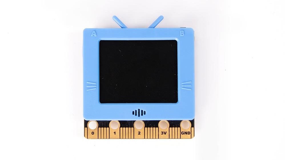
The all-new KittenBot Future board comes with a decently sized 160×128 full-colour TFT screen allowing users to explore the capabilities of the hardware through real-time visual feedback that can be sensor readings. Many students are fascinated by how smart home appliances work. To help them demonstrate simple projects, the KittenBot Future Board comes with support for Wi-Fi and Bluetooth wireless networks. Utilizing these, the newcomers can easily deploy working projects. To do so, we have already seen some block programming tools available in the market. Similarly, we have KittenBot’s Scratch3.0 graphical programming software to make it more interesting for students.
This doesn’t restrict the user to only IoT applications but also works on AI-based projects. Thanks to the onboard speech recognition module that can now work with the Chinese and English language. Along with this, the module also comes with a speaker and LED lights, giving it an aesthetic look with audio-visual feedback. You can now store multiple programs for different projects on the onboard storage that can be expanded with the optional SD card slot. The manufacturer has also provided a light and temperature sensor along with the buzzer that makes it very cost-efficient. Not only this, but if there are several KittenBot Future Boards working together, then they can easily communicate with each other through wireless radio.
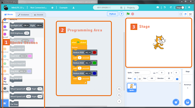
The Kittenblock Graphical programming software
KittenBot has provided the board with a Type-C USB interface to power the board, but those who already own a rechargeable 3.7V Lithium battery can also use it. This light-weight, easy-to-use AIOT Python Education Kit is now sold for $29.99 on the official product page.
The light-emitting diode commonly referred to as LED is a special type of diode with characteristics similar to that of a normal diode. The LED is a device that converts electrical energy into light energy. The LED is a current-driven semiconductor device and when forward-biased emits light of narrow bandwidth depending on the construction of the LED. The emitted light may either be in the visible or non-visible spectrum. LEDs can be categorized as the most widely used semiconductor devices and are mostly used in televisions, colored displays and in road lights, etc.
The LEDs are fabricated to have thin layers of heavily doped semiconductor materials. The semiconductor material and its doping level characterize the emitted light when forward-biased. The different semiconductor materials and the doping levels emit light of different wavelengths. The emitted light in the form of photons is the energy released by the conduction electrons when they recombining with the holes of the valence band. Whilst recombining, a sufficient amount of energy is released to produce monochromatic light by photon.
Physical Construction
The physical appearance and construction of LEDs are different from that of the conventional diode. Normally, the PN junction of a LED is covered by strong transparent epoxy resin having a hemispherical shape. This construction not only helps in protecting the delicate construction of LED but also acts as a lens to concentrate/ focus the emitted light. The light emitted by the PN junction is not of significant strength and would reflect away unnoticeable. However, the construction of domed shaped cover helps the light to focus, strengthen, and to be more prominent.
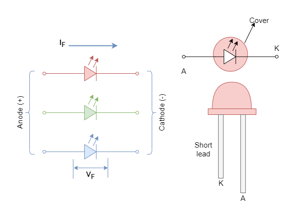
The LEDs with monochromatic light have two legs i.e. anode (+) and cathode (-). The cathode of an LED can be identified by either a flat surface/ notch or by shorter lead. The LEDs are replacing conventional light bulbs because of their efficiency and construction size. The conventional light sources dissipate heat and losses much of the energy whilst LEDs do not heat up producing minimum voltage drop across them. Being an electrostatic device, the LED can be constructed into very small sizes and shapes depending on the application requirements.
Figure 1: The LED symbol and typical shape
Composition of Light Emitting Diode
The composition of the PN junction is selected in a such way to emit a specific wavelength/ color and, as such, the semiconductor materials are deliberately chosen to attain this. The semiconductor materials used in conventional diodes are Silicon and Germanium, whereas, in LEDs, the semiconductor compounds are used such as Gallium Phosphide (GaP), Silicon Carbide (SiC), Gallium Arsenide Phosphide (GaAsP), Gallium Arsenide (GaAs), or Gallium Indium Nitride (GaInN), etc. These compound semiconductors are made by mixing semiconductors in certain ratios/ mixtures to strengthen a specific wavelength.
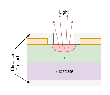
Figure 2: The LED Composition layers
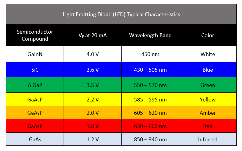
The different compounds and mixing ratios produce light of specific bandwidth in the light spectrum and also characterize the intensity of light emitted.
From the above chart, it is clear that what color is emitted by which semiconductor compound and its wavelength. The LED’s cover is usually made of color belonging to emitted light by the PN junction. It is merely to indicate light the color of LED and, additionally, to enhance the output of emitted light.
The most common and cheaply available colors are Red, Green, and Blue which are the primary colors easily produced by semiconductor compounds. Other colors are expensive and are produced by mixing the primary colors.
Types of Light Emitting Diodes
Gallium Arsenide (GaAs): Infrared
Gallium Arsenide Phosphide (GaAsP): Red, Infra-red, and orange
Aluminium Gallium Arsenide Phosphide (AlGaAsP): Red (Bright), orange, and yellow
Gallium Phosphide (GaP): Red, yellow and green
Aluminium Gallium Phosphide (AlGaP): Green
Gallium Nitride (GaN): Emerald green
Gallium Indium Nitride (GaInN): Ultraviolet, green (bluish), and blue
Silicon Carbide (SiC): Blue (substrate)
Zinc Selenide (ZnSe): Blue
Aluminium Gallium Nitride (AlGaN): Ultraviolet
Voltage Drop and Series Resistance
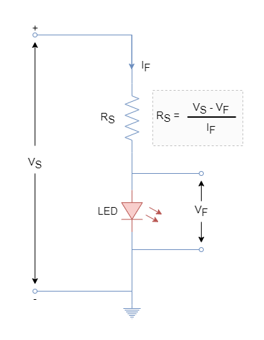
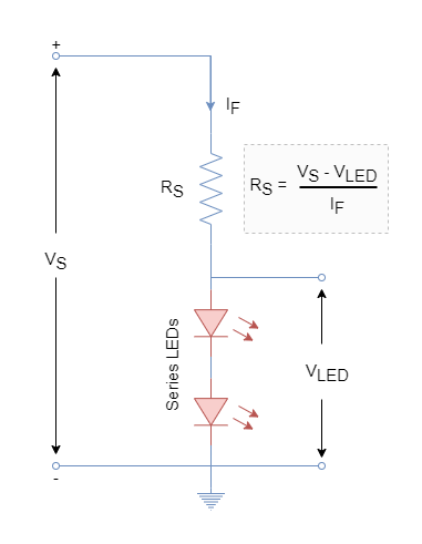
Similar to conventional diode, the LED is current driven and a certain voltage drop occurs when put in forward-biased mode. The forward voltage drop (VF) ranges from 1.2V to 4.0V and is dependent on the type of compound material is used in the LED. The LED emits a light when a voltage greater than the forward voltage drop is applied and the current flows through it. The excessive current flow can damage the sensitive PN junction of LED and as such requires that a proper series resistance be inserted in between the LED and voltage source. The value of series resistance should be such that it does not permit more than 80% of the rated current of the LED and should permit a sufficient amount of current to significantly brighten the LED.
Figure 3: Single LED in series with the resistance
A Single LED Example
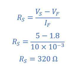
The value of series resistance can be determined using Ohm’s Law. For this purpose, the forward voltage drop (VF), forward current (IF), and supply voltage (VS) should be known. For example, for a red color LED: VF = 1.8 V, forward current limited to IF = 10 mA and voltage supply VS = 5 V. Then value of series resistance (RS) required for the red LED is:
The standard value resistance of 330 Ω is suitable for the selected red LED. The higher valued resistance is selected than the calculated one to remain under the safe limit of forward-current.
Multiple LEDs
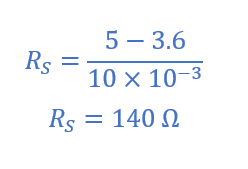
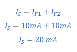
The multiple LEDs can be connected in series and as such driving current will be the same for the LEDs in series. However, for the selection of series resistance, voltage drop (VF) for each LED must be considered. For example, a two red LED circuit will drop a voltage of 2 X 1.8 = 3.6 V and series resistance (RS) should be calculated as follow:
For two LEDs, a series resistance of 140 Ω is required to provide 10 mA of driving current.
Figure 4: Multiple LEDs in series with the resistance
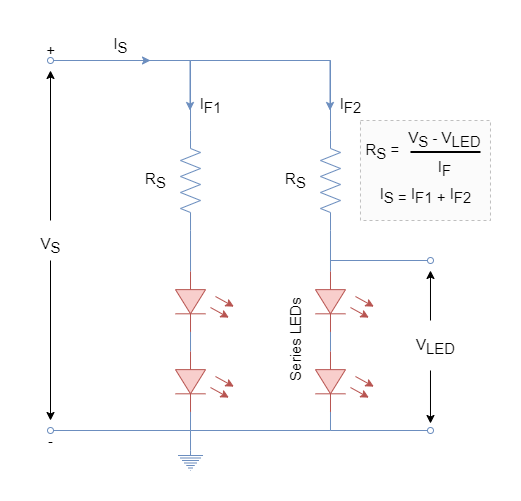
Similarly, a series and parallel combination of multiple LEDs can be made. Another branch of two red LEDs can be added in parallel to the previously constructed circuit to have a total of four LEDs driven by the same power source. The current in each branch will be same i.e., IF1 = IF2 = 10 mA. However, the source current (IS) will be doubled to drive the four LEDs.
Figure 5: Multiple LEDs in series and parallel configuration
Controlling LEDs
The LEDs can be controlled i.e. turning ON & OFF through a number of ways. Mostly, LEDs are used in low voltage digital circuits where they are driven by microcontrollers or logic gates. The logic gate or microcontroller pin can act as input or output. When the pin is set as output it acts as a current source and as a sink in input type. The capability of current handling as source or sink varies and may range from 20 mA to 50 mA. This also indicates that a series resistor is mandatory for the digital circuit to avoid damaging the LED.
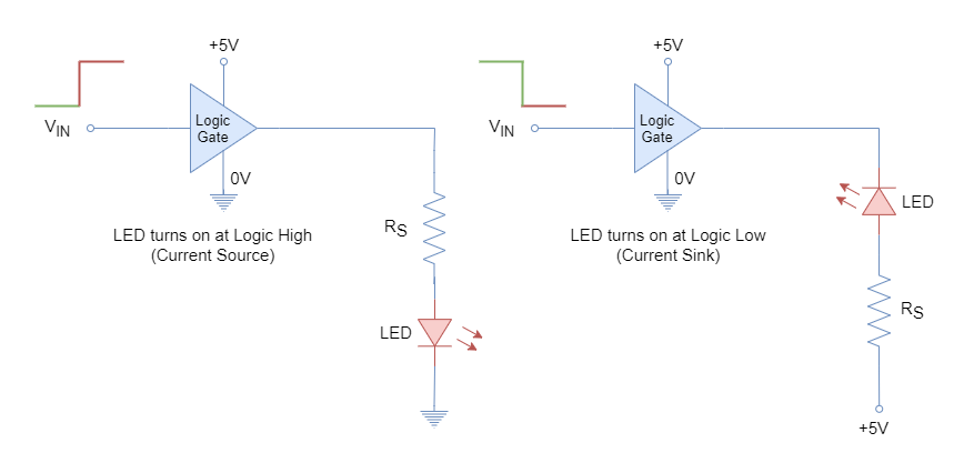
In the following figure, a TTL or CMOS logic is used to drive a LED. The value of the series resistor can be calculated in the same way described earlier. The logic gate is connected to LED as a source as well as a sink in the figure.
Figure 6: Driving LEDs through digital circuits
When the cathode of LED is connected to the ground and anode to the logic circuit through a resistor. Then a logic high will turn ON the LED and vice versa. The logic gate is acting as a source in this configuration. On the other hand, when an anode is connected to logic high voltage through a resistor and cathode to the logic circuit then a logic low will turn ON the LED and vice versa. Digital gate acting as a sink in this configuration.
However, due to the power and current handling limitations of logic circuits, a few of the LEDs can be connected directly to them. The external/ isolated circuitry is required to drive a large number of LEDs such as those used in bigger LED displays. A discrete component such as a transistor is used to drive fast-switching LEDs. The rating of the transistor can be carefully selected depending on the LEDs to be driven.
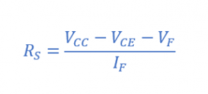
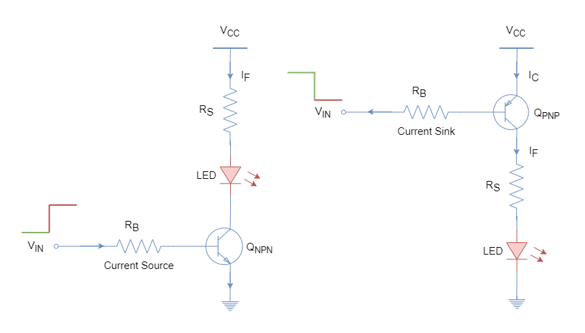
In the following figure, the NPN and PNP transistors are used to drive the LED from a microcontroller or a logic circuit. The series resistor is to be calculated using the following formula:
Figure 7: Driving LEDs through digital circuits isolated by transistors
The logic high and low driving circuits using transistors are shown. The logic source is connected to the base of the transistor and switches ON & OFF the transistor depending on the logic and circuit. The switching ON of the transistor in active mode will complete the LED circuit and turns ON the LED.
Multi-colored LEDs
The single-color LEDs are most commonly used for indications purposes or in seven-segment displays. They are low cost due to simple construction and are available in different sizes & shapes. Besides single-color LEDs, the bi-color and tri-color LEDs are also most commonly used to display different states such as power or battery level, etc.
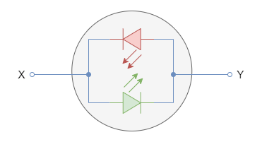
A bi-color LED has two different color LEDs connected in inverse-parallel configuration. The bi-color LED has two terminals and supply from either side produces a color. The reversal of polarity changes the color produced by the LED. These are used for checking battery polarity terminals or other indications etc.
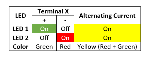
The alternating or bidirectional current applied to it turns ON & OFF both LEDs at a considerably high rate. The switching is undetectable by the naked eye and hence a mixture of both colors is observed.
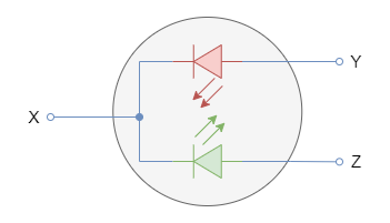
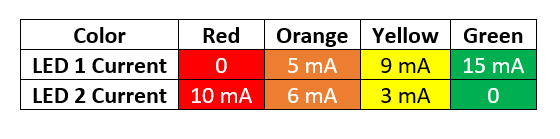
A multi-colored LED comprises red and green LEDs which are connected in parallel to each other. The color emitted by the compound LED is dependent on the driving current of both individual LEDs. The emitted color is the combination of both individual LEDs and their driving current source. The following figure shows a multi-colored LED and its driving current color table.
Applications
Indication purposes.
Seven segment displays for displaying numbering data.
Handheld devices, flat-screen LED televisions, and large-screen displays for advertisement.
Infrared-driven devices such as remote controls.
Opto-couplers
Conclusion
A light-emitting diode converts electrical energy into light energy.
A light-emitting diode is a type of special diode whose PN junction is made from a compound semiconductor.
The LED comprises of heavily doped semiconductor and has a very thin layer of PN junction.
The forward-biased LED enables the electrons in the conduction band to recombine with the holes in the valence band. In doing so the electrons release the energy in form of photons/ light.
The color emitted by the photons is dependent on the semiconductor compound used in the LED and its intensity is dependent on the forward biasing current.
The wavelength of the emitted color lies in the visible or invisible light spectrum.
The series resistance is used essentially to avoid damaging the LED(s) and the value of series resistance requires to be calculated depending on the LED type, number of LEDs, and their series/ parallel configuration.
The LEDs are available in a variety of colors. The monochromatic colors are widely used and cheap. Whereas, bi-color and multi-color LEDs are also available but comparatively costly.
The LED applications include, but not limited to, indication purposes, displays, televisions and large advertisement displays, etc.
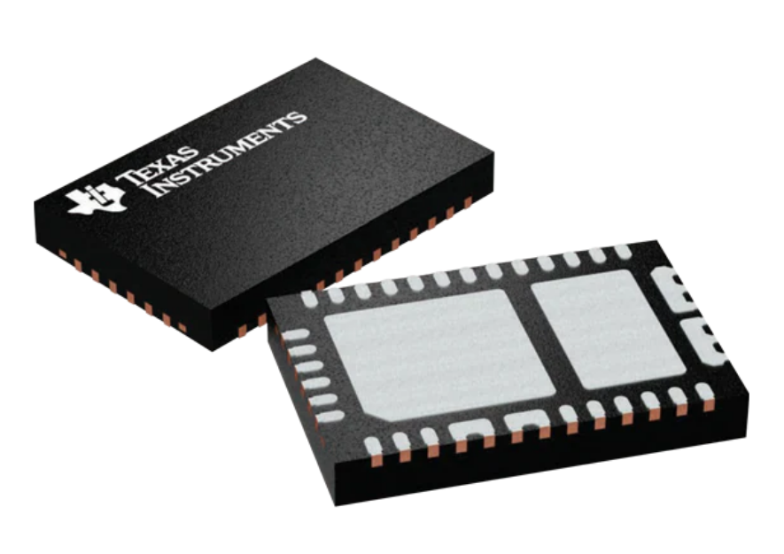
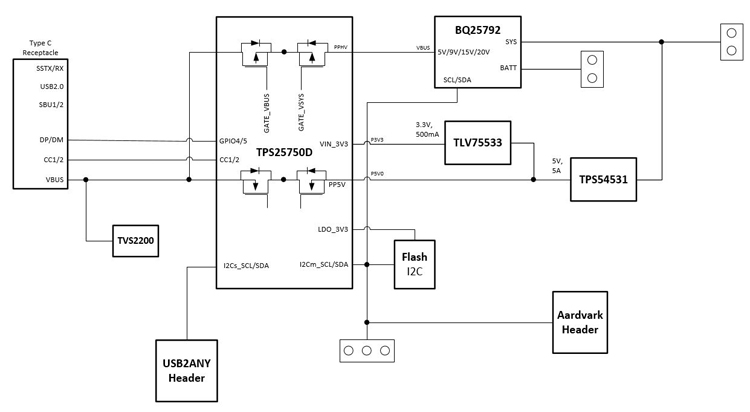
Texas Instruments TPS25750 USB Type-C & Power Delivery (PD) Controller is optimized for applications supporting USB-C PD Power. The TPS25750 integrates fully managed power paths with robust protection for a complete USB-C PD solution. The Texas Instruments TPS25750 also integrates control for external battery charger ICs for added ease of use and reduced time to market. The intuitive web-based graphical user interface (GUI) will ask the user a few simple questions on the application’s needs using clear block diagrams and simple multiple-choice questions. As a result, the GUI will create the configuration image for the user’s application, reducing much of the complexity associated with competitive USB PD solutions.
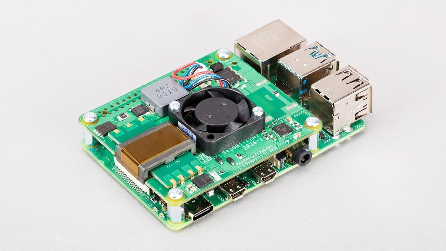
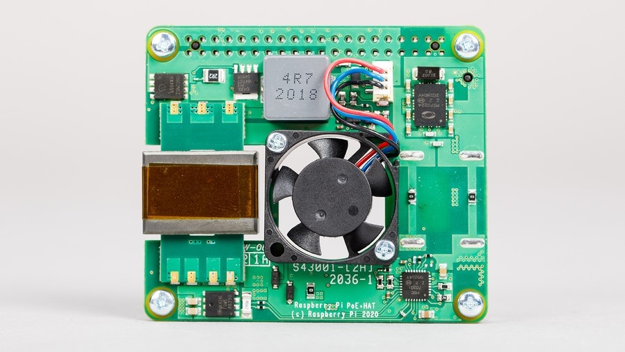
If you start a project on your favorite SBC in the market, Raspberry Pi, then you want fewer cables to run around the hardware. When you power the Raspberry Pi, you also require a separate ethernet connection that makes it two cables running across the hardware, making it look cumbersome. To solve this issue, we first saw the PoE HAT released a couple of years ago by the Raspberry Pi Foundation that makes this easy and simpler by combining both the cables into one. Now with this HAT, you can power the SBC over the ethernet. If we have one official PoE HAT in the market, why do we need yet another one? Let’s say you want to deliver more power than 20 watts, then the normal PoE HAT doesn’t support this due to the operation of only 802.3af.
The all-new PoE+ HAT comes with the support for 802.3af as well as 802.3at. Now, if you wonder why so much power is required, think of a device like a camera or a video IP phone, then in such cases, PoE HAT doesn’t work. But if you only plan to use Wi-Fi, then the predecessor can be a good option. However, due to the same pricing, it does not really matter in terms of cost. Another change that comes with this hardware is to reduce heat dissipation.
“We replaced the diode rectifier with an “ideal diode” rectifier, in the form of a Microchip PD70224ILQ device,”
the manufacturer notes.
If you buy this PoE+ HAT, then you don’t need to make any changes to the main controller board, in this case, Raspberry Pi 3B+ and 4B other than updating the Pi’s software. The fan that sits on top of the HAT is controlled by the I2C connection with Raspberry Pi and works automatically depending on the temperature of the processor. The same pricing as the predecessor of $20 makes it one of the best options if you need PoE+ HAT for your Raspberry Pi-based projects. Depending on where you live, the availability of the board varies, but for those living in the US, SparkFun is up for pre-orders but with no estimated shipping date. It would be interesting to see camera-based projects on your Raspberry Pi using this PoE+ HAT.
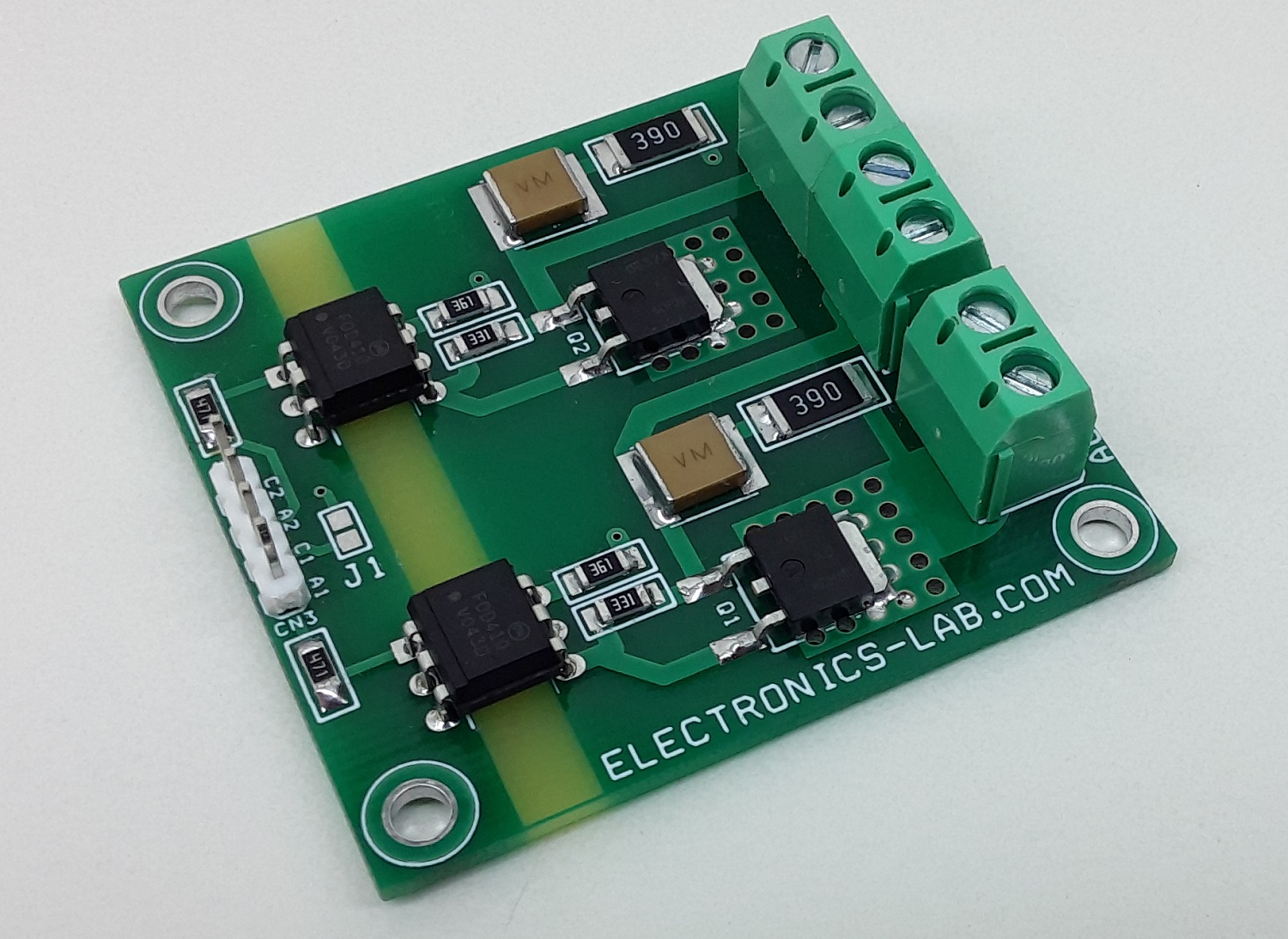
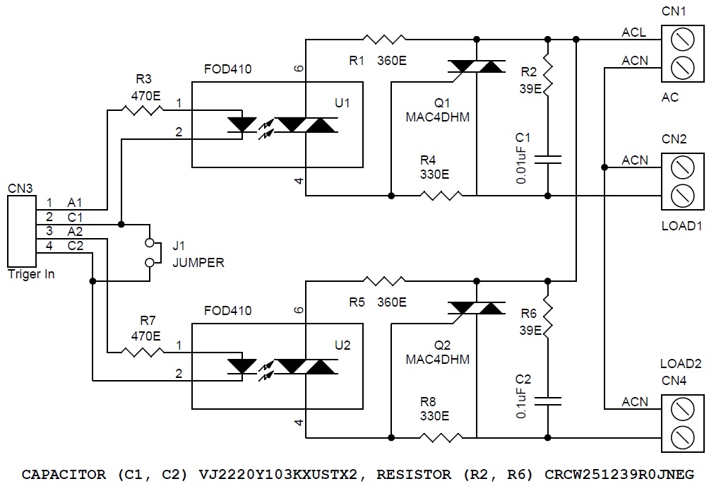
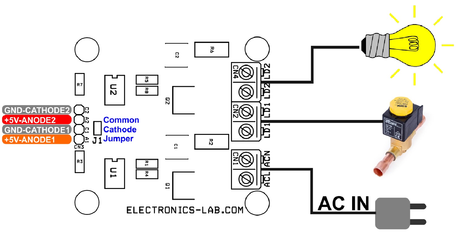
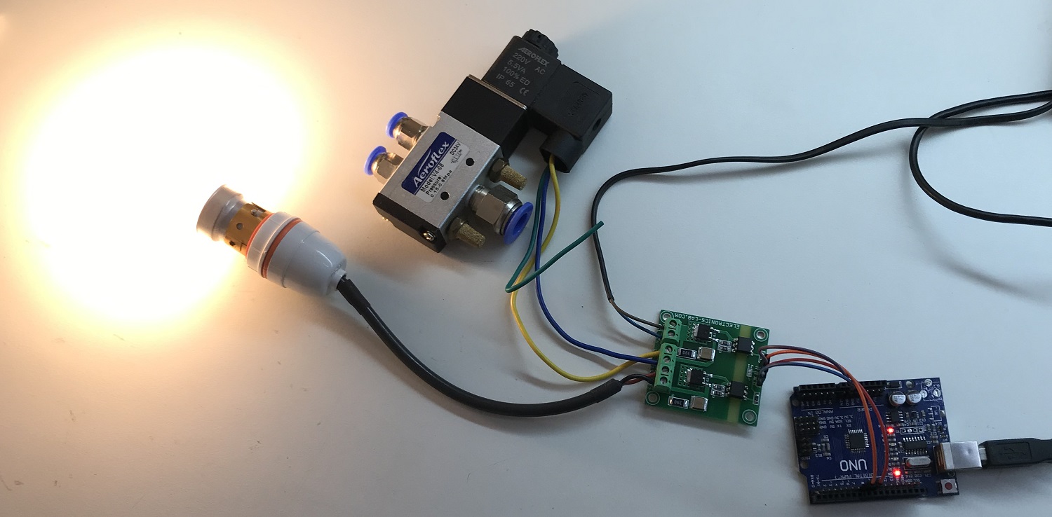
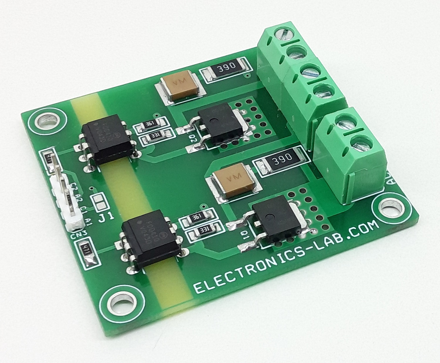
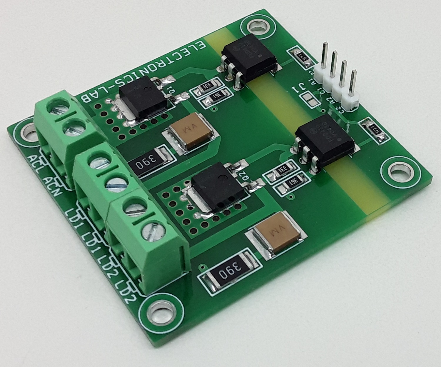
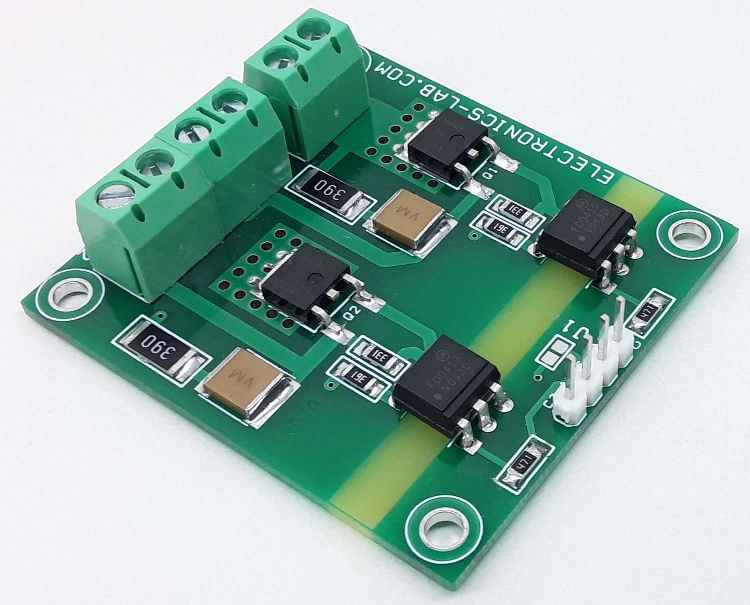
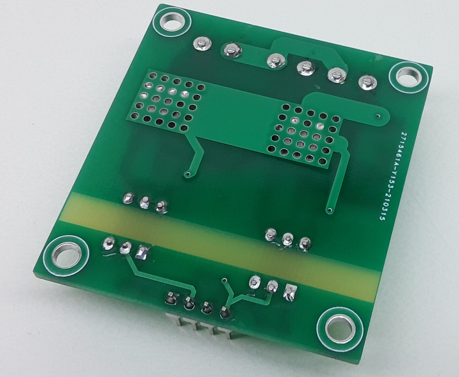
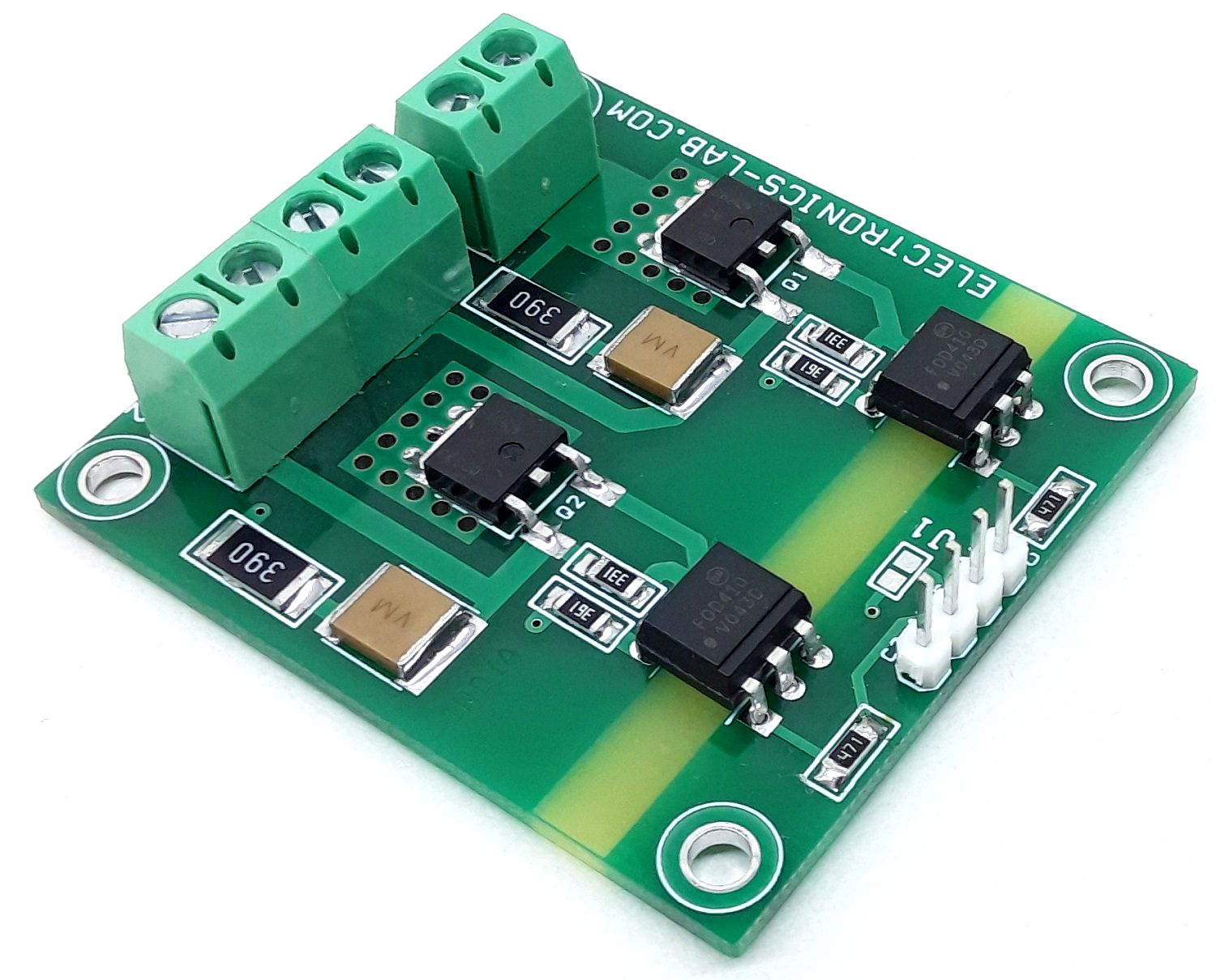
This project offers an extremely compact solution for interfacing 2 high voltage resistive or inductive loads. At a low profile, this is the most compact & versatile optically isolated 2 channel solid state relay system. The circuit consists of 2x Triacs and isolated Triac drivers. The circuit is compatible with TTL input signals and controls 90V-220V AC loads. Sscrew terminal connectors are provided for an easy connection of the AC loads and AC supply input. Interfacing an Arduino/Micro-controller or other circuit is easy using the 4 Pin header connector. A snubber circuit across Triacs is formed using R2, R6, C1, and C2 and is optional for inductive loads. For resistive loads do not populate the snubber circuit. Resistors R3, R4 are for current limiting for internal LED of the isolator. Use jumper J1 for common cathode, otherwise, 2x anode and cathode can be used. Each channel can drive a load up to 100W (220V AC). This circuit can on/off load like Solenoid, AC motor, Fan, Lamp.
What is Solid State Relay??
A solid-state relay (SSR) is an electronic switching device that switches on or off when an external AC or DC voltage is applied across its control terminals. It serves the same function as an electromechanical relay, but has no moving parts and therefore results in a longer operational lifetime.
Arduino Code
Arduino example code available as a download to test the board. Connect A1, A2 ( Anode) to Arduino D8, D9, and C1, C2 (Cathode) GND.
Features
AC Supply 90V to 220V AC
Load 100W X 2
Trigger Signal TTL Compatible (3-5V) (Anode and Cathode)
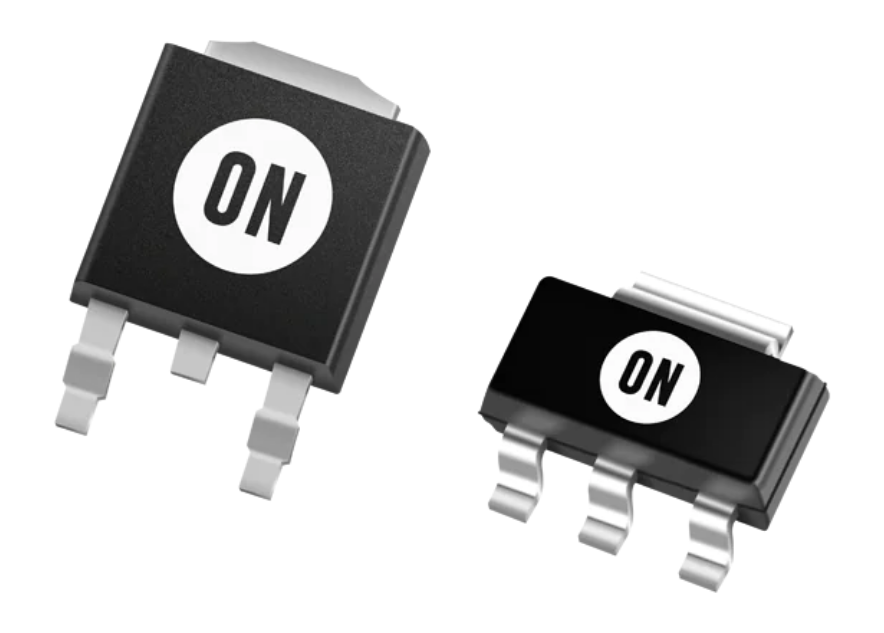
ON Semiconductor NCP1117 LDO Regulators provide an output current in excess of 1.0A with a maximum dropout voltage of 1.2V at 800mA over temperature. The series contains nine fixed output voltages of 1.5V, 1.8V, 1.9V, 2.0V, 2.5V, 2.85V, 3.3V, 5.0V, and 12V. The output voltages have no minimum load requirement to maintain regulation. Also included is an adjustable output version that can be programmed from 1.25V to 18.8V with two external resistors.
Features
Output current in excess of 1.0A
1.2V maximum dropout voltage at 800mA over temperature
Fixed output voltages of 1.5V, 1.8V, 1.9V, 2.0V, 2.5V, 2.85V, 3.3V, 5.0V, and 12V
Adjustable output voltage option
No minimum load requirement for fixed voltage output devices
Reference/output voltage trimmed to ±1.0%
Current limit, safe operating, and thermal shutdown protection
Operation to 20V input
NCV prefix for automotive and other applications requiring unique site and control change requirements; AEC-Q100 Qualified and PPAP capable
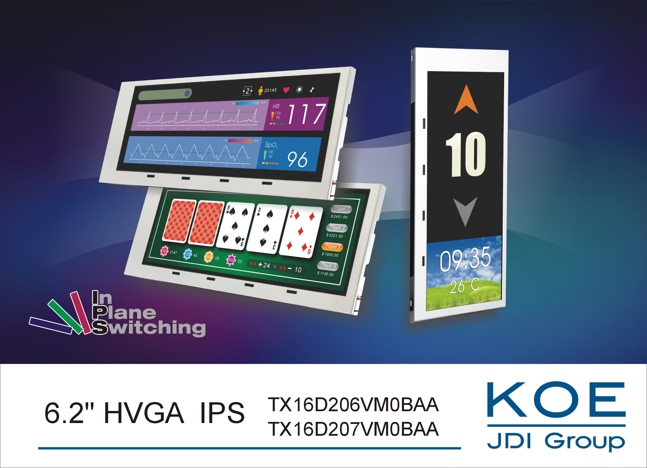
Industrial LCD manufacturer KOE (Kaohsiung Opto-Electronics) has announced the introduction of a new high-performance 6.2-inch TFT display module. The TX16D206VM0BAA TFT display features HVGA resolution (640 x 240 pixels), a wide 8:3 aspect ratio, and IPS (in-plane switching) technology which delivers exceptional optical performance.
The KOE TX16D206VM0BAA display module provides the ideal solution for use in process control systems, industrial HMI, and medical monitoring equipment. Featuring the latest IPS display technology, the 6.2-inch display delivers excellent colour saturation and image stability, high contrast and highly saturated black levels. Exceptional all-round viewing angles of up to 170° are enabled (left/right, up/down).
The 6.2-inch display module provides strong optical performance, with a contrast ratio of 1200:1 and a long lifetime white LED backlight with a specified brightness rating of 400cd/m². These key features ensure that display images are bright, consistent and exhibit high accurately colour reproduction.
Benson Huang, marketing manager, KOE said:
“In-plane switching technology provides highly consistent colour and accurate image reproduction. These are essential requirements for display systems used in medical, audio visual, professional broadcast and a growing number of industrial applications. The 6.2-inch display offers a compact but versatile letterbox format which can be easily accommodated in product designs for measurement and monitoring equipment, and rack-mounted systems.”
The 6.2-inch letterbox format display module has compact mechanical outline dimensions of 173.0mm (w) x 70.0mm (h) x 7.0mm (d) and an active display area of 148.8mm (w) x 53.76mm (h).
A 40-pin CMOS data interface supports 6-bit digital RGB and offers a color palette of up to 262K colors. Also available from KOE are 6.2-inch TFT display modules supporting a LVDS data interface and touch screen options.
With continuity of supply essential for many industrial, medical, and professional applications and systems, KOE is fully committed to developing and manufacturing premium, high quality display modules, and ensuring long-term product availability.
KOE’s new TX16D206VM0BAA can now be sourced and supplied for a minimum period of 5 years. The 6.2-inch TFT display module is now available from KOE’s worldwide sales channel and distribution partners.
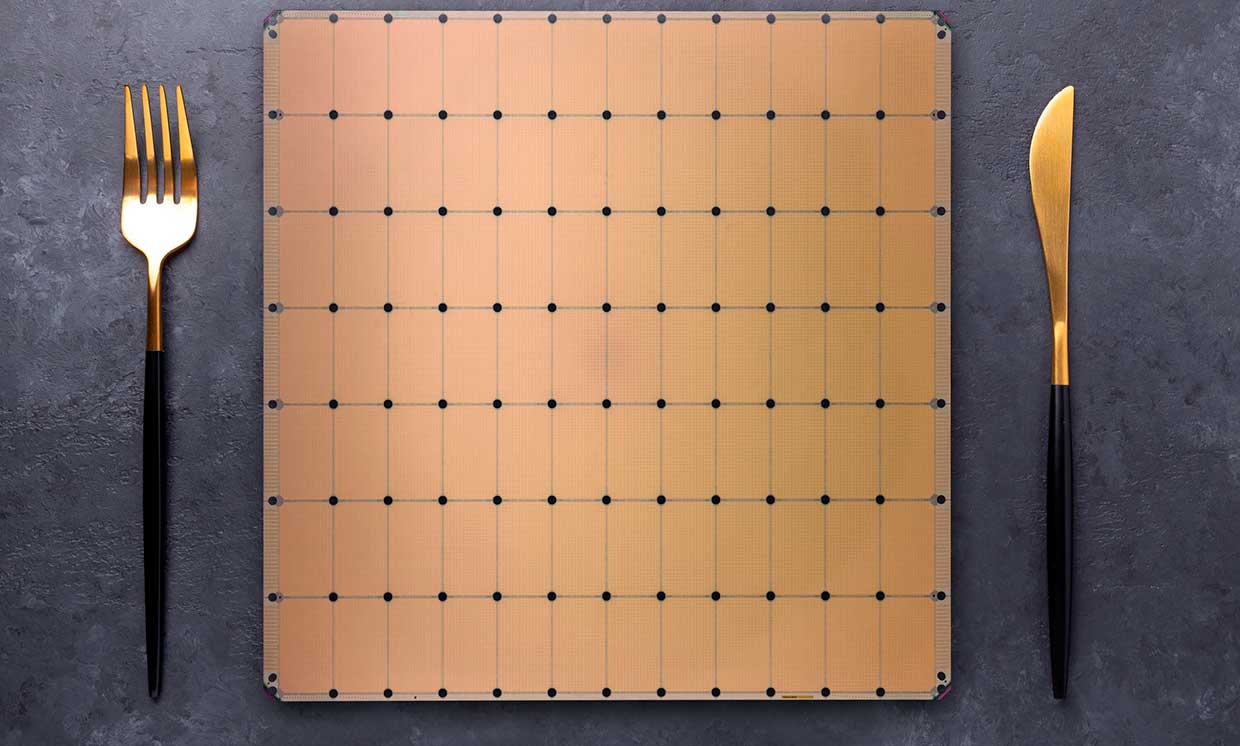
In 2019, we saw one of the largest single computer chips manufactured by a California-based AI startup, Cerebras, that unveiled the Wafer-Scale Engine for deep learning applications. The 1.2 trillion transistors-packed Wafer-Scale Engine came with 18GB of on-chip SRAM and an interconnect speed of 100 Pb/s (Petabytes per Second). After two years of development, the manufacturer has launched the next generation WSE-2 at the Linley Spring Processor Conference 2021.
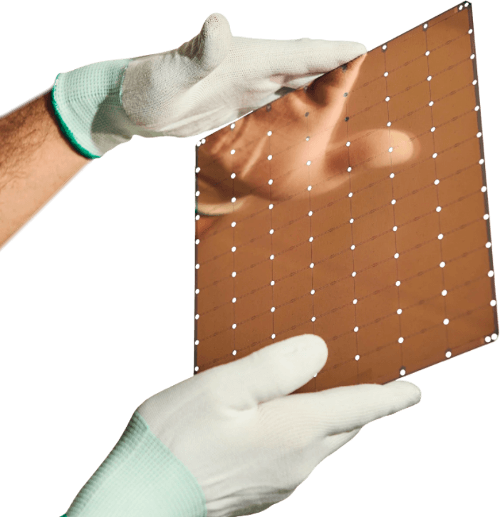
To meet the computational requirements of deep learning tasks, the all-new Wafer Scale Engine comes in the same size as its predecessor of 46,255 mm2 but features more capabilities than ever before. The Cerebras Wafer Scale Engine 2 packs 2.6 trillion transistors with more than 800,000 cores, making it the most powerful single computer chip ever made that is entirely optimized for deep learning workloads.
“In AI compute, big chips are king, as they process information more quickly, producing answers in less time—and time is the enemy of progress in AI,”
Dhiraj Malik, vice president of hardware engineering, said in a statement.
With the increase in training time for deep learning models that are distributed over thousands of GPUs makes it more complex for deployment. This one device takes care of everything, “making orders-of-magnitude faster training and lower-latency inference easy to use and simple to deploy.” The Wafer Scale Engine adds 40 GB on-chip SRAM and an interconnect speed of 220 Pb/s, which is more than double the predecessor keeping the exact size of the wafer.
Like the first-generation Wafer Scale Engine, the AI-cores are easy to program with a robust Cerebras software platform integrating with widely used machine learning frameworks, including TensorFlow and PyTorch. For more details on the new high-performance Wafer Scale Engine, it is available on the product page, but no information on the pricing yet, so we expect it to be costly.
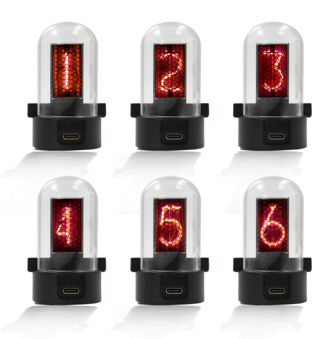
Nixie tube is an electronic device for displaying numerals or other information using glow discharge. When a voltage is applied between two electrodes in a glass tube containing low-pressure gas, the flow of electric current through the gas makes plasma. This phenomenon is called glow discharge. First introduced in 1955, the Nixie displays are legendary. The retro nixie displays had a single anode, multiple cathodes shaped like numerals 0-9 stacked on top of one another. Applying the power to one cathode will make the numeral glow. The tube is filled with a low-pressure gas that creates an orange glow discharge. These legendary displays, however, are no longer mass-produced. Maybe there are a few of them being made which are very expensive. In addition, they need high-voltage drivers.
Therefore, simple replicas are being created that look very much like nixie displays, and they work effectively. Here, mostly the numbers are engraved on ten transparent plates and are stacked on top of one another. LEDs are used for illumination from the edge of each plate. The LEDs light up, and only the number selected is displayed; everything else remains transparent.
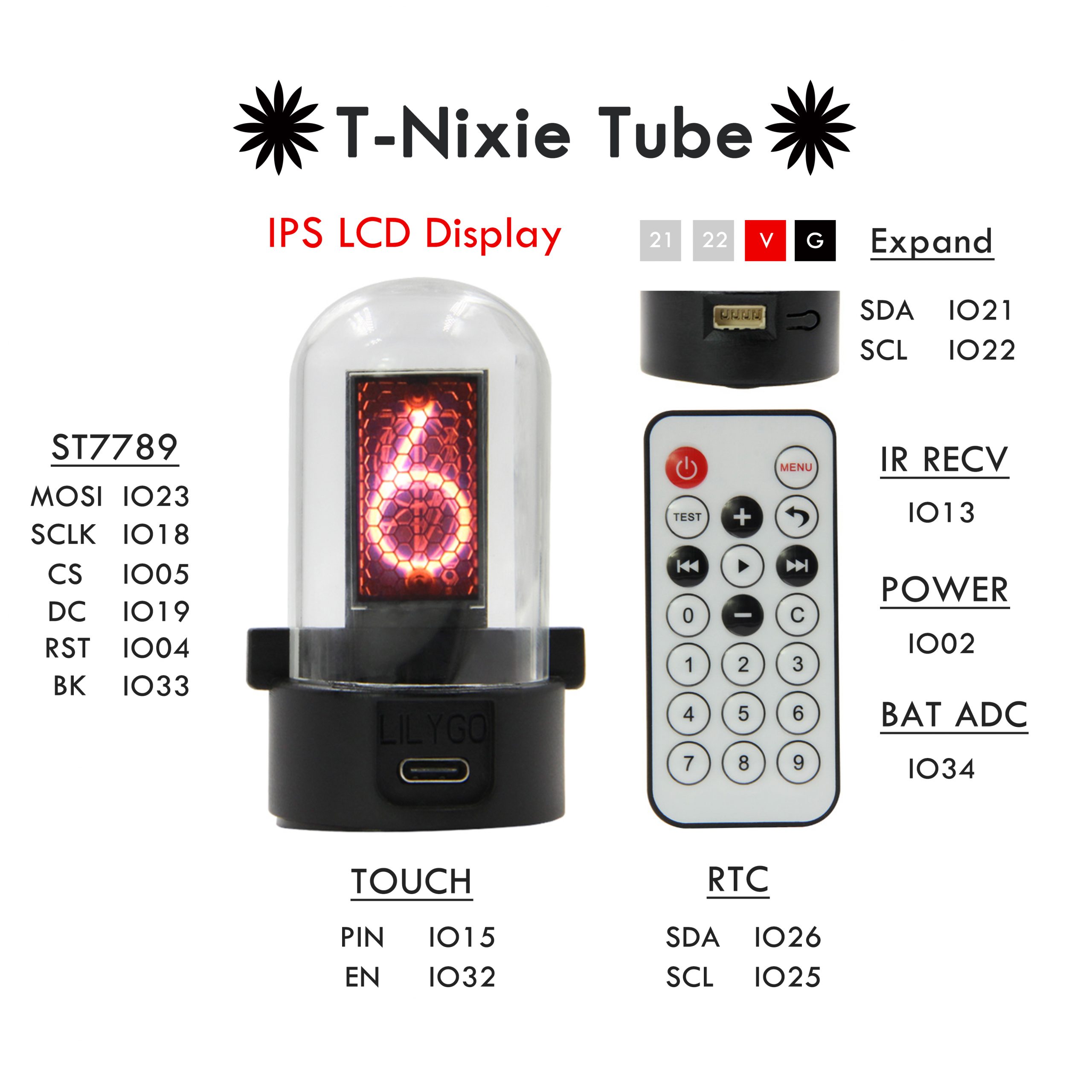
Nowadays, nixie displays are implemented by IPS LCDs which can not only display numerals but images that you can upload via your computer. LILYGO TTGO Simulation Nixie tube or the T-Nixie tube is the nixie tube ‘lookalike’ which is based on IPS LCD. It is based on the LILYGO TTV product motherboard with a 16:9 1.14-inch IPS screen, which is made by adding a cylindrical glass tube to simulate the appearance of a Nixie tube. The tube can be controlled via the standard infrared remote control. Further, it is programmable, which means we can display any content on the tube. Arduino and Micropython are the compatible development environments supported by the tube.
Features of the product:
TTGO T-Micro32 module ESP32 V3 Bluetooth and WiFi
4MB Flash
RTC PCF8563
1.14 inch IPS LCD
Glass tube
Infrared receiving sensor
TTP223 touch button
Type-C
I2C/UART (adapt to T-WATCH sensor kit and T-FH interface sensor module)
Reset button
The TTGO T-Micro32 module used in this nixie tube is the Wi-Fi Wireless Bluetooth Module which is similar in functionality to the normal ESP32 module. But the area is reduced by 45% such that more compact devices can be designed.
The T-Nixie tube can be used to learn to program, as desktop ornaments, STEM education, DIY development creation, etc.
“You can learn to develop the simulation Nixie tube interface, dot matrix interface, and other interesting interfaces through the built-in RTC clock circuit of this product.”
The kit is sold on Aliexpress costing 27.5 USD. T-type USB cable and an IR remote control along with the T-Nixie tube.
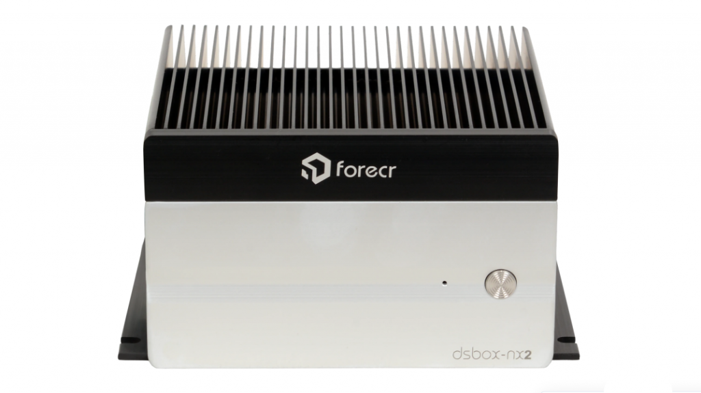
With the increasing popularity of the NVIDIA Jetson Xavier NX for its high-performance best-in-class deep learning accelerator, many manufacturers in the embedded electronic devices have started to release modules that work on this AI-edge device. One of the most recent releases was the industry’s first industrial AI smart camera for AI vision solutions. With the continued growth of adoption of NVIDIA Jetson Xavier NX, Forecr that is known for its NVIDIA Jetson based Industrial BOX PCs comes with the newly launched DSBox-NX2. This fanless box PC is specifically designed for industrial applications.
The next-generation industrial computer gives supercomputer performance multi-stream deep learning edge analytics with options to choose from the SSD storage that goes up to 2TB. The claim of supercomputer performance comes from the capability to decode up to 32 video streams in 1080p at 30fps, which is very unlikely to happen with the Raspberry Pi SBC. The famous NVIDIA processor gives 21 TOPS AI performance, which is more than enough for many of the mission-critical applications that require high-performance deep learning accelerators.
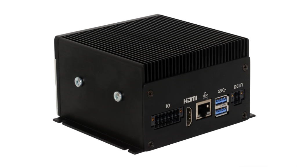
With all the information on the product page, it is very clear that this PC plans to be the best-in-class for vision-AI applications that sometimes require multiple stream video processing using deep learning algorithms. For this, NVIDIA’s DeepStream is a complete SDK for AI-based multi-sensor processing that comes from video, audio and image. Giving such high performance and utilizing the CPU and GPU at their fullest makes us think about the heating and operating temperature of the device. Thanks to the manufacturer, with a broader range of operating temperatures of -25⁰C to +65⁰C and the fanless system makes it perfect for any and all kinds of industrial applications.
The manufacturer has designed the BOX PC with rich interfaces that lets you connect a high-resolution camera through a USB interface or even expand the storage through SSD on M.2 slot. After the initial testing by the manufacturer, the throughput of over 7 GB/sec with PCIe Gen 4 M.2 SSDs was observed. “Gigabit Ethernet utilization tests show over 900MBits/sec compared to the 1 Gbps theoretical limit of this interface.”
Those who are interested in the product can look for more information on the product page where it is priced at €749 and goes up to €1189 for a 2TB SSD.