Stefan Wagner’s NeoController Tests and Controls NeoPixel LED Strips

NeoPixel Tester

When you buy any small development board, one of the first things you try is interfacing the programmable NeoPixels. One such example we saw was in the case of Raspberry Pi Pico, which interfaced the NeoPixels using the programmable IOs. If you have been following the maker community, you might have heard about Stefan Wagner and his exciting projects. Lately, he [Stefan Wagner] has designed a tester built on the ATTINY 13 microcontroller for 800kHz NeoPixel strips.

With the small form factor of 21.6mm x 11.4mm you can easily solder the PCB to the NeoPixel LED strip without any problem. However, while designing the tester, he realized the amount of capabilities ATTINY 13 microcontroller could showcase. With this thought, he went ahead and added an IR receiver to the PCB that can control some of the parameters using the IR control remote.

NeoPixel Tester PCB

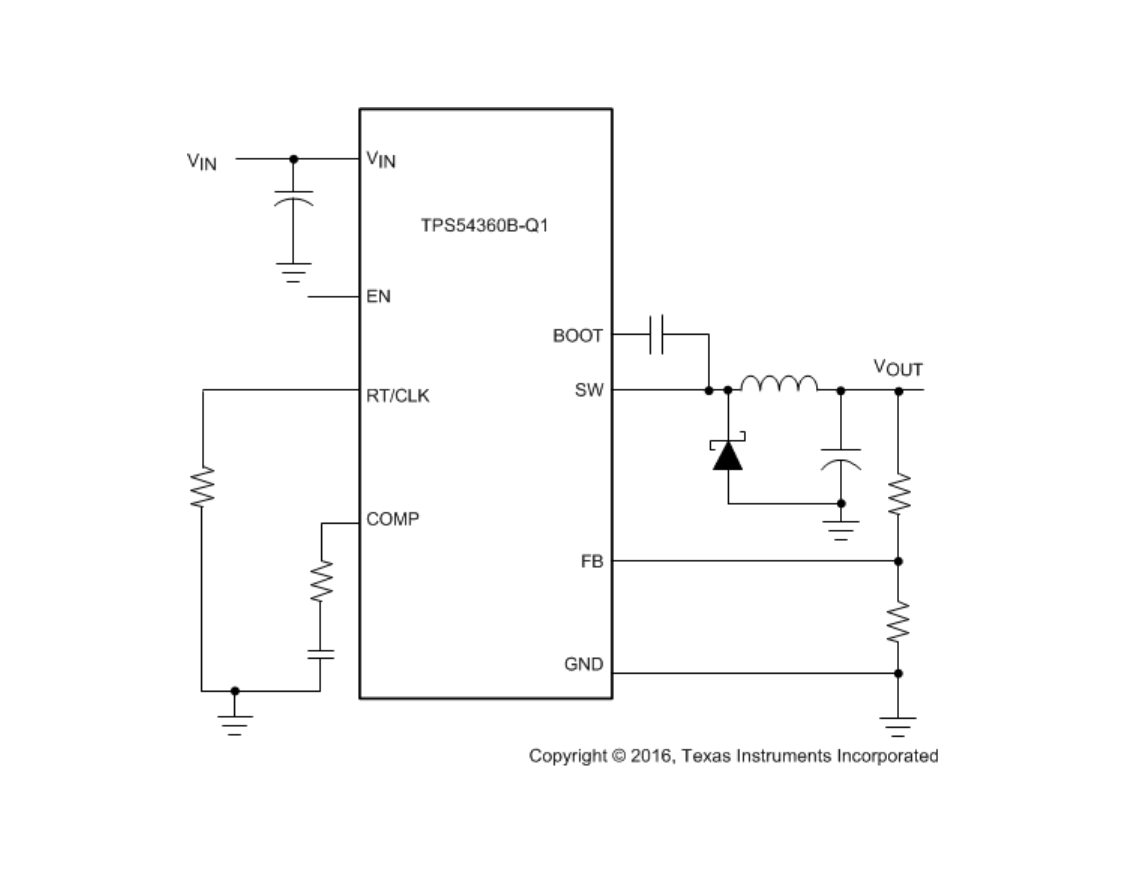
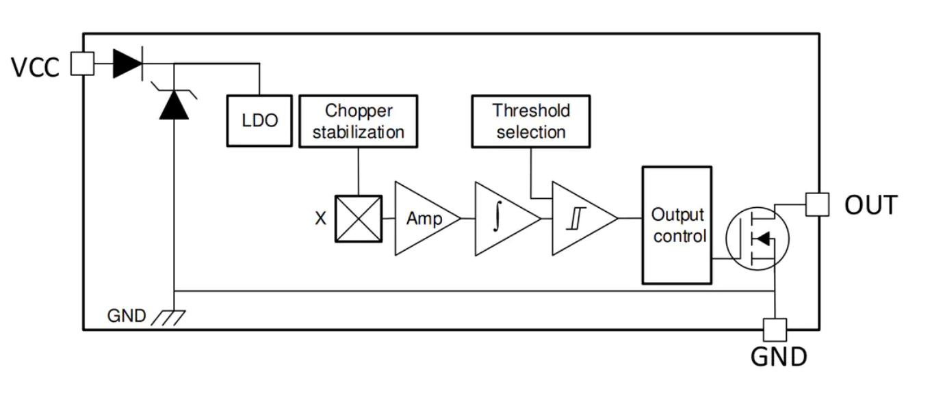
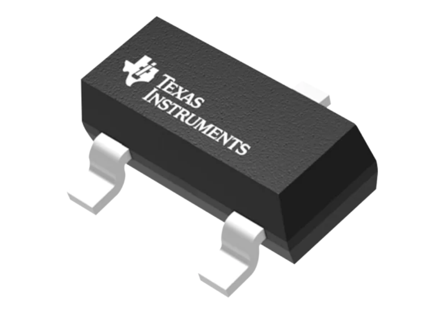
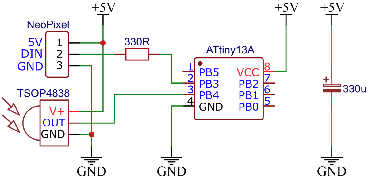
Regarding the hardware circuitry for the tester, it looks very straightforward as shown in the figure below. The microcontroller chip is directly connected to the output of the IR receiver (TSOP4838) and connected to the NeoPixel through a resistor of 330 ohms.

“The control of NeoPixels with 8-bit microcontrollers is usually done with software bit-banging. However, this is particularly difficult at low clock rates due to the relatively high data rate of the protocol and the strict timing requirements,” Stefan explains.

Moreover, after the project, he noticed that the timings mentioned in the datasheet were nowhere close to the actual implementation. He [Stefan Wagner] has provided the timing rules that should work with all 800kHz addressable LEDs in the project’s GitHub repository.

In the end, Stefan notes that more than one-third of the flash memory is available for makers to explore more capabilities of the ATTINY 13 microcontroller for controlling NeoPixels. The IR implementation including decoding and error detection only takes 228 bytes of flash memory. Note that you can also use other 38kHz IR receivers other than TSOP4838.

If you plan to work on this project, you need to program the microcontroller before soldering as there is no ICSP header provided onboard. The designer has given a detailed guide on how to program it using Arduino IDE as well as using the precompiled hex file. Operating instructions are also available in the GitHub repo.

Jupiter Nano – Tiny, high-performance computer that runs Linux, or the NuttX real-time operating system

Jupiter Nano is an open-source hardware development board that runs NuttX RTOS or Linux. It has a tiny 48-pin form factor (1.125″ x 2.5″, similar in size to the Teensy 4.1) and is 10x more powerful than the Arduino Due.

Jupiter Nano is perfect for Arduino users who need a tiny, powerful computer with more CPU power, lots of RAM, or an internet-connected real-time operating system (NuttX). It should also be attractive to any Linux users who need a tiny, open-source hardware computer with lots of I/O and high-speed Wi-Fi. The applications for a board this small, and this powerful, are nearly endless.

Features & Specifications

  • Open-source hardware development board
  • Runs NuttX RTOS or Linux
  • Size: Tiny 48-pin form factor (1.125″ x 2.5″, similar in size to Teensy 4.1)
  • Programming: JTAG port for programming and debugging
  • CPU: Microchip SAMA5D27C-LD1G running at 498 Mhz
  • DRAM: AP Memory AD2100XXX 128 M x 32 LPDDR2 DRAM chip integrated into system-in-package (SIP)
  • Power management: Quorvo ACT8945A with integrated LiPo battery charging capability
  • Power delivery: Compatible with many LiPo batteries
  • Designed in KiCAD: the hardware design can be altered using 100% open source KiCAD software
  • 10x more powerful than the Arduino Due:
    • ARM Cortex A5 processor running at 498 Mhz (7x clock speed of the Arduino Due)
    • 128 MB RAM (1280x RAM of Arduino Due)
    • Key peripherals use DMA (USB, SPI, I2C, Flexcom)
  • I/O:
    • USB 2.0 HS port on USB-micro B jack (Port A, 480 Mbps, host or device)
    • USB 2.0 HS port on a pin-header connection (Port B, 480 Mbps, host only)
    • USB 2.0 FS Debug console port on USB-micro B jack (12 Mbps)
    • SD Card slot – 50 MHz DDR – device boots from the card (this means it is impossible to brick the device)
    • Native SPI and I2C ports
    • 4 FLEXCOMs on I/O pins – flexible serial controller peripherals that can be SPI, UART, or I2C

Open Source

Open-source information, such as the board KiCAD files, schematics, project files, and software will be provided once the campaign is fully funded.

Photos and text are sourced from www.crowdsupply.com

TPS54360B-Q1 – Automotive, 60V Input, 3.5A, Step-Down DC-DC Converter With Eco-mode

Texas Instruments TPS543xx/-Q1 and TPS545xx/-Q1 are 42V input 3.5A and 5A step-down DC-DC converters with an integrated high side MOSFET. TI TPS54360 and TPS54560 are 60V input 3.5A and 5A DC-DC converters with integrated high side MOSFET. TPS54341 / TPS54541 and TPS54361 / TPS54561 devices offer 100kHz to 2.5MHz adjustable switching frequency while TPS543x0 and TPS545x0 devices have 100kHz to 2.5MHz fixed switching frequency. These TI step-down converters survive load dump pulses up to 65V per ISO 7637. All of the parts offer high efficiency at light loads with pulse skipping Eco-mode. The TPS543xx-Q1 & TPS545xx-Q1 devices are AEC-Q100 qualified for automotive applications.

Sample Application

Features

  • Integrated High Side MOSFET
  • High Efficiency at Light Loads with Pulse Skipping Eco-mode
  • 100kHz to 2.5MHz Fixed or Adjustable Switching Frequency
  • Internal Soft Start
  • -40°C to 150°C TJ Operating Range

more information: https://www.ti.com/product/TPS54360B-Q1

Axiomtek’s Server-Grade ATX Motherboard Powered by the Latest 3rd Gen Intel® Xeon Scalable for AI and HPC Applications – IMB700

Axiomtek – a world-renowned leader relentlessly devoted in the research, development, and manufacture of series of innovative and reliable industrial computer products of high efficiency – is proud to introduce the IMB700, its new server-grade ATX motherboard powered by the latest dual LGA4189 socket 3rd Gen Intel® Xeon® scalable processors (code name: Ice Lake-SP) with the Intel® C621A chipset. Featured with built-in AI and crypto acceleration functions as well as advanced security capabilities, the IMB700 is targeted at markets requiring accelerating performance, high security, high-performance computing for efficient machine and deep learning workloads.

“Axiomtek’s IMB700 is built on the server-grade 3rd Gen Intel® Xeon® Scalable platform with up to thirty-eight powerful cores and a wide range of frequencies, features and power levels. To respond to the need for heavy workload processing and intensive computing data transmission, the IMB700 has six 288-pin DDR4-3200 RDIMM sockets with a memory capacity of up to 384GB. It also features rich data storage and flexible expandability to satisfy customer-specific needs in deep learning AI, video surveillance, industrial automation and other diverse applications,”

said Wayne Chung, the product manager of IPC Division at Axiomtek.

The IMB700 offers rich expandability with three PCIe x16 slots, three PCIe x8 slots and M.2 Key M 2280 interface with PCIe x4 signal for adding GPUs, capture cards, RAID cards, high-speed NVMe storage, etc. Six SATA-600 ports with integrated RAID 0/1/5/10 are available for reliable data storage and protection. For a wide range of I/Os, it has an internal USB dongle, six USB 3.1 Gen1 ports, seven USB 2.0 ports, one RS-232/422/485 port, two GbE LAN ports with Intel® Ethernet controller i210-AT, one VGA port, eight-channel programmable digital I/O port, one HD Codec audio, SMBus, and one PS/2 keyboard and mouse. Trusted Platform Module 2.0 (TPM 2.0) is available to ensure critical information security. Furthermore, it can operate under a wide temperature range from 0°C to +60°C for use in harsh environments. More features include watchdog timer and hardware monitoring functions.

Advanced Features of the IMB700

  • LGA4189 socket Intel® Xeon® Scalable processor (code name: Ice Lake-SP)
  • Six 288-pin DDR4-3200 RDIMM sockets for up to 384GB of memory
  • Supports multiple graphic card slots
  • Three PCIe x16 and three PCIe x8
  • Supports M.2 Key M 2280
  • Supports TPM 2.0 (optional)
  • Supports internal USB dongle

The IMB700 is going to be ready for purchase in June 2021. For more product information or customization services, please visit our global website at www.axiomtek.com or contact one of our sales representatives at info@axiomtek.com.tw.

Texas Instruments TMAG5123 High-Voltage Hall-Effect Switch

Texas Instruments TMAG5123 High-Voltage Hall-Effect Switch is a chopper-stabilized omnipolar, active-low, in-plane, Hall-effect switch sensor. The TMAG5123 eases mechanical placement of the sensor by measuring magnetic fields parallel to the surface of the printed circuit board (PCB) in a surface mount SOT-23 package.

Different sensitivity levels are available to match the specific requirement of the application. When the applied magnetic flux density value exceeds the operating point (BOP) threshold in absolute magnetic field values, the open-drain output produces a low-state voltage. The output remains low until the applied field decreases to less than the release point (BRP) threshold also in absolute terms.

The Texas Instruments TMAG5123 incorporates a wide 2.5V to 38V operating voltage range and reverse polarity protection of up to -20V, enabling robust operation for industrial applications.

Features

  • In-plane, omnipolar Hall-effect switch
  • High magnetic sensitivity
    • TMAG5123B (4.1mT (typical))
    • TMAG5123C (7.5mT (typical))
    • TMAG5123D (10.9mT (typical))
  • Supports a wide voltage range
    • 2.5V to 38V operating VCC range
    • No external regulator required
  • Wide operating temperature range
    • -40°C to +125°C ambient operating temperature range
  • 30kHz continuous conversion
  • Open-drain output
  • SOT-23 package option
  • Protection features
    • Supports up to 40V load dump
    • Reverse battery protection to –20V
    • Output short-circuit protection
    • Output current limitation

Block Diagram

more information: https://www.ti.com/product/TMAG5123-Q1

zzh!: CC2652R based development board for multiprotocol RF tinkering

We are all aware of the multiprotocol RF shields for Arduino development boards. These RF shields gave RF capabilities to the board and made them compatible with the modules such as RFID, XBee, or Bluetooth. Electrolama, based in the United Kingdom, released a tiny “USB stick” form-factor development board for multiprotocol RF tinkering. The stick is named zig-a-zig-ah! (zzh, for short).

“Think of it as an upgrade to the ubiquitous CC2531 USB Sticks commonly used for Zigbee tinkering,” Omer Kilic, the developer of this USB stick, describes the design. “CC2652R has a much beefier processor, more memory, and a sane free compiler option that should enable easier development compared to the old CC2531 based option.”

The board is powered by a CC2652R SimpleLink microcontroller from Texas Instruments. CCR2652R is a 48MHz 32-bit Arm Cortex-M4F microprocessor-based multiprotocol 2.4 GHz wireless MCU with 352kB Flash storage, 8kB of cache static RAM that is configurable as general-purpose RAM, and 80kB of ultra-low-leakage SRAM with parity protection. The microcontroller is a multiprotocol 2.4 GHz wireless microcontroller (MCU) supporting Thread, Zigbee, Bluetooth 5.2 Low Energy, IEEE 802.15.4, IPv6-enabled smart objects (6LoWPAN), and many other systems. It features a low standby current of 0.94 µA with full RAM retention, increasing the battery life and making it suitable for low-power wireless communication systems.

zzh is an easy-to-use device. For communication with the host computer, no manual driver installation is required in most cases, and the communication can be easily performed via the common CH340 USB-UART bridge.

The board consists of the following additional features:

  • Self-programming via the TI CC-series serial bootloader. As long as it is not explicitly disabled in code, no external programmer is needed! Pushbutton on the default pin to trigger this mode
  • cJTAG debug header, in case you disable BSL by accident or want a proper debug interface
  • SMA antenna port for an external antenna of your choice
  • Secondary uFL port for measurements or an alternative antenna.
  • General-purpose LED

The project is designed by Electrolama / Omer Kilic and licensed under the Solderpad Hardware License 2.0. The board is available for sale on Tindie. The documentation and a “User Manual” for zzh can be found on the project page and design files in the Github repository.

Omer says,

“A portion of each sale will be donated to @Koenkk to support his work on Zigbee2mqtt and the public firmware images used by zzh and many other projects.”

About Electrolama

Electrolama is a collection of open-source projects and various other frivolities by Omer Kilic and friends.

mxiot, your low-cost hardware prototyping platform

Jaydcarlson has posted on GitHub details about mxiot, which is a low-cost hardware prototyping platform, which enables you to explore switching small IoT projects from bare-metal to a secure-boot-capable WiFi/BT-connected Embedded Linux system capable of running rudimentary C/C++, and also applications written in almost any modern language or application framework (like Qt, Rust, Ruby, Python, Node.js, or .NET Core). At the core of mxiot is the i.MX6ULZ, a 900 MHz Cortex-A7 microprocessor. These are drop-in compatible with the i.MX6UL and i.MX6ULL.

The board features:

  • 3 UARTs (one with hardware flow-control signals, and one dedicated to the console)
  • Two I2C peripherals (one shared with one of the UARTs)
  • SPI with 2 chip-select signals
  • I2S with separate BCLK/WS signals for TX and RX paths.
  • 4x PWM outputs
  • Two USB ports

Apart from the DRAM and SD Card socket necessary for booting, mxiot also features WiFi and Bluetooth connectivity, 4x 12-bit analog inputs, care of the Texas Instruments TLA2024 APA102 addressable RGB LED QSPI Flash (that you can optionally boot from), and Pushbutton. WiFi and BLE are enabled via whatever 44-pin standard SDIO-interfaced WiFi/BT module du jour you’d like to add; the board supports all physically compatible Ampak modules.

The design is open-source, and more importantly, the BOM has wide availability and doesn’t lean on ICs with limited documentation or support. This means you can prototype your project around the mxiot and then copy the guts into your own design to optimize for size, power consumption, cost, or expanded functionality.

mxiot’s part are tightly arranged onto a dense 6-layer PCB measuring only 2.3 x 0.8 inches (58 x 20mm). The i.MX6’s OTP key storage, TrustZone, and secure-boot capabilities enable you to establish a chain of trust from the boot ROM to U-Boot, to the kernel, and an encrypted roots, which will enable you to store private data without you having to worry as much about physical device security. It also offers the ability to transport firmware updates over unencrypted channels, and you do not have to worry about your image being reverse-engineered or modified.

Regarding the board’s durability, he says:

“OSHPark’s test 6-layer service and JLC’s 6-layer service have both been tested with the gerber files and the resulting boards pass stress-tests.”

The boards cost roughly $100 when ordered with ENIG. He also recommends ordering an electropolished solder stencil. He also plans to do some EMC chamber testing to see if the impedance mismatches on the JLC boards cause more pronounced emissions. mxiot is easy to assemble. It is designed to be hand-assembled with a kitchen hotplate and a low-cost hot-air gun. To assemble, follow these steps: paste up the top side of the PCB, place the components, and heat with a hot plate until the solder becomes molten.

For more information, visit the project page on Github.

All NEW $61 Banana Pi BPI M2 Pro For Multimedia Applications

Banana Pi BPI-M2 Pro SBC

We saw several Banana Pi that not only competes with Raspberry Pi but also OrangePi and Beagle boards. SinoVoip Co. Limited has released a new product to its long list of ARM-based SBCs, Banana Pi BPI M2 Pro, which is similar to the Banana Pi BPI-M2+ because they share the same number of interfaces. If you already own a Banana Pi BPI-M2+, then you can use the same case due to the same form factor.

The all-new next-generation Banana Pi BPI M2 Pro comes with the Amlogic S905X3 quad-core Cortex-A55 processor running at 1.9 GHz clock frequency that uses 12nm manufacturing process technology. The Amlogic S905X3 SOC also integrated Cortex-M4 processor with neural network accelerator that helps the user to run neural network workloads on this tiny SBC. Along with this, the support for 4K at 75 frames per second has added the advantage to wirelessly transmit large video files using the HDMI cable and inbuilt Wi-Fi support.

Banana Pi BPI-M2 Pro

Banana Pi BPI M2 Pro gives the manufacturer two options of choosing 2GB and 4GB DDR4 RAM; however, SinoVoip Co. Limited has chosen to use 2GB RAM for the SBC that gives you not the best-in-class performance when compared to other powerful SBCs but can surely be at par for specific applications. The manufacturer has compared this newly launched SBC with the Banana Pi BPI-M5 because of the same SOC. Still, as mentioned earlier, the M5 model gets the 4GB RAM variant but does not support Bluetooth wireless network.

For those looking for an SBC with a neural network accelerator for light workloads, this is a good option, but the onboard RAM can be a problem for processing. Similarly, for heavy workloads, the user can choose the Banana Pi BPI-M5 single-board computer with almost the exact specifications but with 4GB RAM. Even though the board comes with 16GB eMMC flash storage, you can expand it up to 64GB. Adding more to the storage, the board also gets a microSD card slot that can help you increase the onboard storage to up to 256GB.

The board is designed to operate on the Linux and Android operating systems. If you are interested in buying the product, head to the product page on AliExpress, where it is priced at $61.

SATRAN: A Wifi-controlled satellite antenna tracking system

An antenna tracking system adjusts the axis of an antenna to follow a moving signal source like a communication satellite. The working of an antenna tracking system is quite simple; the antenna is, first of all, commanded to move in any direction. Then, the level of the received signal is compared with the previous signal intensity. If the strength of the received signal has increased, the antenna is commanded to move in that direction. If the signal level of the received signal has gone down, the antenna moves in the opposite direction, and in this way, an antenna tracking system follows a communication satellite.

The tracking system consists of two main parts: a control part and the physical structure of the antenna. The control part is responsible for making the two-axis positions of the antenna follow a predefined trajectory during satellite tracking. There are two degrees of freedom for an antenna, namely azimuth, and the elevation angle. The elevation angle is used to define how up in the sky the antenna must face. The azimuth angle, on the other hand, tells us in which direction the antenna should face. An azimuth value ranges from 0 to 360 degrees. Here, north is 0 degrees, and when you change the antenna face to the east, it will be 90 degrees and so on. When you return to facing north, completing the rotation, it will read 360 degrees.

The elevation value ranges from 0 to 180 degrees. When the satellite is overhead, the value will be 90 degrees, and when at the horizon, the value will be 0 degrees. So, it is easy to point at the sky with the help of azimuth and elevation values.

Daniel Nikolajsen from Sweden shared his compact satellite antenna tracking device SATRAN. SATRAN is an azimuth/elevation rotator that can be controlled via an android app and can be 3D printed at home. The rotator of the project has a 3D printed mount that is compatible with many different kinds of antennas.

Daniel says about his project;

“This is a continuation of an old project of mine when I built a simple satellite antenna tracker with an android app that calculates the position of any satellite using its “Kepler elements”, and controlling the Az-El antenna rotator to track it across the sky. During a few late nights together with two other ham operators, we built a crappy but functional prototype from spare parts. Now some years later, I decided to redesign it from the ground up as an affordable and easy to use kit.”

The tracker is based on the ESP8266 NodeMCU board, adding WiFi compatibility. It can be controlled manually in a web interface or automatically through an android app. Plus, for controlling the angles, Nema17 stepper motors are used. SATRAN can be used to listen to various satellites using generic SDRs (Software Defined Radios), or it also can be used to receive satellite imagery or other data. The maker said that the two-way communication to the satellites can also be tried out.

The maker comments on its use:

“Many “CubeSats” are now also in orbit – small, privately funded satellites built by schools, universities, and enthusiasts. Even the international space station regularly transmits images by radio, using what is called as Slow Scan TV.”

The kit for the SATRAN tracking device can be found here: https://www.satran.io/

VIAVI Reveals mOSA Optical Spectrum Analysis Module, Enhancing Trusted Test Portfolio for Lab and Manufacturing

New mOSA Module expands comprehensive VIAVI MAP Optical Manufacturing Platform

VIAVI Solutions Inc. (VIAVI) (NASDAQ: VIAV) today introduced the mOSA Module, adding optical spectrum analysis to the VIAVI Multiple Application Platform (MAP) Optical Manufacturing Test system. The mOSA complements existing VIAVI solutions for optical power measurement, switching and signal conditioning, and test automation, further enhancing the industry’s most comprehensive test portfolio for development and manufacturing of optical communications technology.

The new MAP mOSA Module offers exceptional web and touchscreen user interfaces, and a 30% improvement in measurement resolution as compared to similar products on the market today. A member of the LightDirect family of hot swappable test modules, the single slot mOSA is a fraction of the size of legacy optical spectrum analyzers, reducing the valuable automated manufacturing test system footprint by up to six rack units. Joining the seventeen application modules already released for the VIAVI MAP System, the addition of the mOSA Module allows customers to leverage the full integrated power of the industry’s most widely deployed optical test platform.

“Optical communications manufacturers are racing to keep up with demand for next generation coherent and ethernet optical interfaces. Simultaneously, testing precision continues to increase, while pressure to hit aggressive cost targets has never been higher,” said Tom Fawcett, Vice President and General Manager, Lab and Production Business Unit, VIAVI. “Our new mOSA optical spectrum analyzer leapfrogs the competition in both performance and density, perfectly complementing the VIAVI MAP system that delivers unmatched scalability, efficiency and precision to meet escalating demands for optical manufacturing testing.”

To learn more about new VIAVI solutions for cost-effective development and manufacturing of communications technology, visit the virtual exhibition during OFC 2021, June 7-11.

About VIAVI

VIAVI (NASDAQ: VIAV) is a global provider of network test, monitoring and assurance solutions for communications service providers, enterprises, network equipment manufacturers, government and avionics. We help these customers harness the power of instruments, automation, intelligence and virtualization to Command the network. VIAVI is also a leader in light management solutions for 3D sensing, anti-counterfeiting, consumer electronics, industrial, automotive, and defense applications. Learn more about VIAVI at www.viavisolutions.com. Follow us on VIAVI Perspectives, LinkedIn, Twitter, YouTube and Facebook.

TOP PCB Companies