Siemens accelerates digital marketplace strategy with acquisition of Supplyframe for USD 0.7 billion

Siemens has signed an agreement to acquire Supplyframe, a leading Design-to-Source platform for the global electronics value chain, for USD 0.7 billion. The transaction unlocks significant value for customers of Supplyframe and Siemens, providing seamless and quick access to both Siemens’ offerings and Supplyframe’s marketplace intelligence. This will help customers to reduce costs, increase agility and make highly informed decisions. The acquisition also strengthens the Siemens portfolio through Software as a Service (SaaS) – not only in the field of Electronic Design Automation (EDA) and Printed Circuit Boards (PCB), but also scaling into other domains and technology fields.

“We are very pleased to welcome Supplyframe’s highly innovative and talented team to the Siemens family. Supplyframe will be the nucleus to accelerate our overall digital marketplace strategy,” said Cedrik Neike, member of the Managing Board of Siemens AG. “Supplyframe’s ecosystem and marketplace intelligence complements our industrial software portfolio perfectly and strengthens our capabilities for the growing market of small- and mid-size customers.”

“Eighteen years ago, we set out on a journey to intelligently connect the extended electronics value chain. It took both a dedicated team and a visionary customer base to gradually turn our vision into reality. This process has been further accelerated by the recent component shortage environment, which has exposed the fragility of supply chains and created a mandate for digital transformation and intelligent decision making. I am thrilled to join forces with Siemens to scale our innovation and drive broader adoption of our DSI solutions globally.  This is an amazing outcome for our customers, partners and employees,” said Steve Flagg, CEO and founder of Supplyframe.

Supplyframe has created a strong Design-to-Source Intelligence (DSI) ecosystem with over 10 million engineering and supply chain professionals worldwide, transforming how businesses design, source, market and sell products in the global electronics value chain. Supplyframe’s SaaS offerings have been growing with ca. 40% p.a. over the last years, a rate that is expected to continue mid-term.

Highlights:

  • Siemens to acquire Supplyframe, a leading and fast-growing marketplace for the global electronics value chain
  • Combining Supplyframe’s knowhow with Siemens’ leading software enables customers to innovate and develop products faster
  • Supplyframe to be the nucleus of Siemens’ digital marketplace strategy
  • Closing of transaction expected in fourth quarter of fiscal year 2021

Siemens will realize significant synergies between Supplyframe’s capabilities and its own portfolio with an expected USD mid-triple digit net present value. EPS accretive pre-ppa in second year after closing. Steve Flagg will continue as CEO of the company and join the Siemens Digital Industries Software senior leadership team.

Founded in 2003, Supplyframe is headquartered in Pasadena, California with offices in the USA, China, France, Serbia, and the UK. The expected revenue of Supplyframe for the fiscal year 2021 is around $70 million with profit margins typical for the software business.

Closing of the transaction is subject to customary conditions and is expected in the fourth quarter of the fiscal year 2021.

Automatic LED Stairway Lighting – Arduino Compatible

This creative idea is suitable for a stairway with 16 stairs, each stair can have a 12V LED. It has two sensors one at the start and one at the end of the stairs and when the sensor triggered at any end it starts a process of lighting each of the steps in a progressive cycle starts. When you reach the other side of the stairway and the second sensor is triggered it will start to extinguish all the lit lights in the ascending cycle.

This is a very simple and easy to build project based on the Arduino platform The board consists of an ATMEGA328 microcontroller, 16 channel MOSFETs, 2 optical retro-reflective or optical defuse sensor, 16 x 12V LEDs, LM7805 regulator, DC filter capacitors, and optional current limiting resistor on each MOSFET. The circuit requires 12V DC, each MOSFET can drive a LED up to 1A (0.5 to 12W LED)

Automatic LED Stairway Lighting – Arduino Compatible – [Link]

Nordic Semiconductor nPM1100 Power Management IC

The nPM1100 is a PMIC designed as a complementary component to Nordic’s nRF52® Series.

The nPM1100 is a dedicated power management IC (PMIC) with a dual-mode configurable buck regulator and integrated battery charger. It is designed as a complementary component to Nordic’s nRF52® Series and nRF53® Series System-on-Chips (SoCs) to ensure reliable power delivery and stable operation, whilst maximizing battery life through high efficiency and low quiescent currents. It can also be used as a generic PMIC device for any other suitable application. Its extremely compact form factor makes it ideal for advanced wearables, connected medical devices, and other size-constrained applications. PCB area usage can be as low as 23 mm2.

Key features
  • Ultra-small form factor PMIC
  • 2.075 x 2.075 mm WLCSP package
  • 400 mA battery charger
  • Highly efficient regulator
  • Up to 150 mA of regulated voltage output
  • USB compatible input regulator
  • Overvoltage protection
  • Ship mode disables power output
  • Low quiescent currents
  • Drivers for charge and error LEDs
  • -40°C to 85°C operating temperature

The integrated battery charger is designed to charge lithium-ion and lithium polymer batteries to a termination voltage selectable to 4.1 or 4.2 V supporting cell chemistries with a nominal voltage of 3.6 and 3.7 V, respectively. It includes battery thermal protection and automatic selection of three charging modes: automatic trickle, constant current, and constant voltage. The maximum charge current is resistor selectable from 20 mA up to 400 mA. The charger also features a discharge current limitation and is JEITA compliant.

The highly efficient step-down buck regulator can deliver up to 150 mA of current at a selectable output voltage of 1.8, 2.1, 2.7 or 3.0 V. It features soft startup and automatic transition between hysteretic and PWM modes. It also allows a forced PWM mode to ensure clean power operation.

Block Diagram

The nPM1100 PMIC features a USB compatible system regulator that features USB port detection for SDP, CDP and DCP USB host-type ports supporting USB current limits of 100 mA and 500 mA, and a USB supply voltage ranging from 4.1 to 6.6 V. The system regulator features a 20 V overvoltage protection that allows for transient voltage peaks of up to 20 V. The regulator allows a system voltage output ranging from 3.0 to 5.5 V.

The typical quiescent current of the nPM1100 PMIC is 700nA in power off mode, which can be further reduced to 470 nA in “ship mode”. Ship mode also disables power output and thus removes the need for an external power switch.

The nPM1100 PMIC requires no software to operate and is compatible with all components that operates within the output voltages and power the PMIC can deliver, while charging lithium-ion and lithium-polymer batteries at 4.1 V or 4.2 V. The PMIC itself operates from either USB or other DC power (4.1 V to 6.6 V) or from a connected battery (2.3 V to 4.35 V).

more information: https://www.nordicsemi.com/Products/Power-Management/nPM1100

PAC1710 Current Sensing Monitor IC’s

Microchip’s high-side bidirectional current sensing monitor ICs come in a RoHS compliant DFN package

The PAC1710 from Microchip Technology is a high-side bidirectional current sensing monitor with precision voltage measurement capabilities. The power monitor measures the voltage developed across an external sense resistor to represent the high-side current of a battery or voltage regulator. The PAC1710 also measures the SENSE+ pin voltage and calculates average power over the integration period. The PAC1710 can be programmed to assert the ALERT# pin when high and low limits are exceeded for current sense and bus voltage. It is available in a RoHS compliant 3 mm x 3 mm 10-pin DFN package.

The PAC1710 device is good for measuring dynamic power. The long integration time allows for extending system polling cycles without losing any power consumption information. In addition, the alert ensures that transient events are captured between the polling cycles. These current sensing products are ideal for notebooks, desktop computers, industrial, power management systems, and other embedded applications.

Sample Application

Features

  • High-side current sensor
    • Current measurement is integrated over 2.5 ms to 2.6 sec with up to 11-bit resolution
    • 1% current measurement accuracy in positive range
    • Measures VSOURCE voltage
  • Calculates proportional power
  • VSOURCE voltage range 0 V to 40 V
    • Bidirectional current sensing
  • Auto-zero input offset voltage
  • 3 mm x 3 mm DFN-10 package
  • Digital averaging
    • Adjustable sampling time and resolution
  • 5 µA typical standby current
  • Programmable sense voltage range
    • ±10 mV, ±20 mV, ±40 mV, and ±80 mV
  • Power supply range 3.0 V to 5.5 V
  • Wide temperature operating range: -40°C to +85°C
  • ALERT# output for voltage and current out of limit transients between sampling interval
  • SMBus 2.0 communications interface
    • Address selectable by resistor decode
  • Sample time configurable from 2.5 ms to 320 ms
  • With averaging effective sampling times up to 2.6 sec

more information: https://www.microchip.com/wwwproducts/en/PAC1710

Valar Systems’ WiFi Stepper Motor Board with StallGuard Technology

Valar Systems' WiFi Stepper Motor Board

Controlling stepper motors over a WiFI network opens up the possibilities for the integration of wireless and automation functions to your motor applications. We saw a WiFi Stepper board by Good Robotics in January 2019, it featured control over Wifi and enabled an IoT interface for any stepper motor all the way up to 85V and 10A RMS. Additionally, we saw a 3.5A Unipolar Stepper Motor Driver with PWM current control and Micro-stepping.

Recently, Valar Systems launched their VAL-1000 WiFi Stepper Motor Board which comes with a Trinamic TMC2209 motor driver featuring StallGuard and StealthChop functionalities. The board supports WiFi and Bluetooth connectivity, which makes it less complicated to control and allows the mobility of the application hardware. Additionally, the company also provides a mobile application for controlling the motors, thus it becomes, even more, user-friendly. You can also customize the functioning by uploading your own Arduino Code on the device as well.

Technical Specifications of WiFi Stepper Motor Board

Technical Specifications of WiFi Stepper Motor Board

  • Espressif Systems’ ESP32-WROOM-32D dual-core WiFi Controller with 16MB memory.
  • Trinamic TMC2209 motor driver with StallGuard and StealthChop technology.
  • Texas Instrument’s synchronous 12V to 3.3V DC/DC flexible converter
  • Silicon Labs USB/TTL bridge for data communication
  • Two-button inputs for opening and closing the device

Talking more about the Trinamic TMC2209 motor driver, it comes with the StallGuard technology that includes a provision for a fallback mechanism. If the force on the motor exceeds a certain value, the device automatically stops. This decreases potential threats and ensures the safety of heavy mechanical applications. The PTC thermistor on the board ensures additional safety in case of an overcurrent supply in the circuit. Interestingly, the driver’s design principles align with those used in the development of secure platforms like Canada Crypto Casino, where advanced tech ensures safety and efficiency. According to Valar Systems, the driver is comparatively silent and affordable compared to competing motor drivers.

ESP32-WROOM-32D dual-core sits at the heart of the board. Its low-cost to high-performance ratio is unlike any other. It provides stepper motor control as well as maintains the wireless connection for WiFi and MQTT access.”

USB port of WiFi Stepper Motor Board

The micro USB port allows the flashing of firmware on with a less complicated process and can be used as USB-to-UART Bridge. The Wifi Stepper Motor Board also has the provision of an automatic flashing circuit so there is no need to physically open the device to press G0 and Reset.

You can check out the GitHub repository by Daniel Frenkel for exploring the software support of the device. The WiFi Stepper Motor Board is available on Tindie for $29 USD. For information, you can visit the official product page on Tindie’s website. Technical specifications and images have also been taken from the product page.

Inkplate 6PLUS: Verstaile, easy-to-use and energy-efficient Wi-Fi enabled 6-inch e-paper display

E-paper displays are fascinating. They mimic the appearance of ordinary ink on paper, and they look brilliant! E-Paper displays make reading comfortable and provide a wider viewing angle than most light-emitting displays. An idle E-Paper display can be easily viewed in direct sunlight without the image appearing to fade. Moreover, the fact that these screens resemble physical paper and appear lifelike is very captivating.

However, E-Paper display modules are a hassle to work. They require additional hardware like breakout boards for connectors and cables or external microcontrollers. This is where Inkplate 6PLUS recycled E-Paper display from e-radionica comes into the picture. Inkplate 6PLUS is a powerful, energy-efficient, Wi-Fi-enabled ESP32 board with a recycled 6.0-inch e-paper display featuring a touchscreen and front lighting. The Inkplate display is open-source hardware supported by an open-source software library. It is easy to use and convenient for both who prefer Arduino IDE or MicroPython. Also, it consumes power only when updating the content of the display, which means that it can be powered by a small lithium-ion battery and make a compact device out of it.

Source: https://www.crowdsupply.com/e-radionica/inkplate-6plus

The display is very user-friendly. For displaying content, you need to install the board definition, download the library, and open one of the many sample applications. The Inkplate team says,

“Customizing those samples is about as easy as it gets. Using a library based on Adafruit GFX, you can add text, images, and other graphical objects to the screen with just a few lines of code. MicroPython and ESP-IDF libraries and sample code are available as well.”

Hardware is also plug-and-play. All that is needed is a connection via USB Type-C cable, and it is ready to display.

Inkplate 6PLUS uses E-Ink’s latest generation e-paper technology, Carta. It offers high contrast and high resolution; more specifically, it provides 212 Pixel density. Carta technology also provides a wider viewing angle, an expanded temperature range, and a pure reflective mode. Plus, they are touch-sensitive and support 64 levels of brightness. Kindle Paperwhite (2nd and 3rd generation) also uses this technology. The displays used in Inkplate 6PLUS are recycled (from 1st and 2nd generation Kindle Paperwhites, Pocketbook Touch Lux 3s, and possibly Kobo Nias).

The Inkplate’s all-in-one hardware consists of a dual-core ESP32 microcontroller with 4 MB of flash memory, 8 MB of RAM, Wi-Fi connectivity, and an onboard antenna. The microcontroller can be programmed with the help of a USB-to-UART converter as its USB Type-C port simplifies programming. The hardware has an MCP73831 charger that charges its Lithium battery when it is connected to USB power and draws power from that battery when the USB power is disconnected. An onboard charging LED indicates battery status, and battery-measurement circuitry gives easy access to the voltage.

Source: https://www.crowdsupply.com/e-radionica/inkplate-6plus

The hardware includes a 6-inch, 1024 x 758 pixel e-paper display with support for grayscale, partial updates, and quick refresh cycles. MCP23017 IO expanders are used to drive the display and to provide extra GPIO pins. Moreover, it uses AP5726WG-7 and DAC MCP47A1 LED drivers for controlling the 64 different brightness levels. An onboard Real Time Clock (RTC) is utilized to reduce power consumption and keep time. The hardware consumes only 22uA in the sleep state and can go months on a full charge.

This all-in-one, easy-to-use, and highly compatible E-Paper display from the Inkplate family are perfect for a variety of applications such as reading and displaying the calendar, temperature, weather, air quality data, or any art piece.

DNA Transilluminator with Arduino Nano


Gel Electrophoresis is a laboratory method used to separate macromolecules like DNA, RNA, or protein according to their molecule size. The molecules to be separated are pushed by an electric field through a gel that consists of pores. First of all, the macromolecules are loaded into wells at the negative end of the chamber. Therefore, the molecules are now negatively charged. Now, when an electric field is applied, the negatively charged macromolecules are attracted toward the positive side of the chamber. The smaller and more charged the molecule is, the further it will travel towards the positive end of the chamber. In this way, the technique results in the separation of macromolecules according to their mass and charge. Gel Electrophoresis finds its application in forensic science, paternity tests, observing protein levels, and many other fields.

The molecules are generally dyed such that distinct bands can be easily interpreted. After the separation of molecules is performed by the electric field, the location of each molecule in the gel is observed with the help of a transilluminator. The dye used will be fluorescently excited by the UV light. Various staining dyes are excited at different wavelengths of light. Thus, the use of a transilluminator is critical for interpreting results from the Gel Electrophoresis procedure.

Some transilluminators and gel imagers are specifically designed for viewing DNA and protein in electrophoresis. Gabriel St-Pierre recently published an instructable in which he described step by step how to make a Blue Light DNA Transilluminator. The project is built using a UV filter, an Arduino Nano, an LED strip, 3D printed parts and some mechanical items. Gabriel discusses thoroughly how to design and 3D print the required plastic parts, how to assemble the mechanical components like hinges, how to program the Arduino and assemble the components, and at last, how to test the device.

Gabriel mentions in the introduction of the project,

“Students or small laboratories with limited financial support for scientific investigations are often forced to search for alternative methods for analyzing their gels. The present project demonstrates the design and assembly of a DNA transilluminator system using easily accessible components at a respectable cost. The project can be tackled by young students aiming at gaining practical skills in building laboratory equipment or experienced scientists searching for a rapid and cost-efficient method for analyzing gels. The complexity of the project is kept at a minimum. Further modifications can be undertaken to improve the performance of the device. No professional experience in electronics design or software programming is needed.”

The project uses Arduino Nano and an LED strip for illumination. The programming is performed in Arduino IDE, and the author used the Adafruit NeoPixel library. The desired color can be selected by adding “//” to the lines of code associated with the undesired colors.

How to Build a TinyML Smart Weather Station using Wio Terminal

TinyML-Smart-Weather-Station-Using-Wio-Terminal (1)

You might have seen many ML-based projects for weather predictions. Where training of an ML model is followed by testing of the model for good accuracies. This tutorial will learn to deploy a similar type of ML model using an on-board TensorFlow Lite on the Wio Terminal. You will see all the steps for building the smart weather station, starting from data acquisition to deployment.

For this tutorial, you will need a Wio Terminal, an ATSAMD51 Core with BLE 5.0 & Wi-Fi 2.4G/5G dev board, and a Grove – Temperature & Humidity Sensor (DHT11). You will also need Arduino IDE for programming and deploying purposes and Microsoft Visual Studio Code for running python scripts. You can also use other code editors for Python, but Microsoft Visual Studio Code is used in this tutorial.

Getting Started with Data Acquisition: Temperature and Humidity Data

Before training the ML model, you will need past data of your locality on which the model would be trained on. This could be a tedious task as it is difficult to get such type of data. However, you can try getting this data in three ways.

Collecting the Data Using Sensor

One of the easiest ways to collect data is by programming your own hardware through a sensor. This might seem a suitable way, but it comes with a significant drawback. As the data needed for this use case needs to be timely collected for a long time, it is not practical to wait for such a long time. Additionally, you will have to label the data manually as it would be used for supervised machine learning.

grove-temperature-humidity-sensor-dht11

Finding a Free Dataset or API

You can look for a reliable weather dataset for your locality, as there might be sources available for such data types. Although most of these sources might charge you for a subscription, you need to look for free sources critically.

Public APIs for data collection can also be implemented to get the data. You need to pass an input payload with the required parameters for calling the API. The API will output the dataset as its response. “For example, the National Environmental Agency in Singapore offers an API for Weather Data that is free for programmatically querying historical weather data.”

Web Scraping the Data using Python Script

There are many online sources that have detailed weather data of past years which are available for free. Wunderground is one of them but, most of these sources don’t have the downloadable format of data as they are just displayed on the website. For this tutorial, you need data from thein the CSV format which can be easily accessed for training the model. Hence, you can use Python script and libraries for scraping this data and storing it in CSV format.

Here is the python script for scraping the weather data from Wunderground. For detailed information about code and logic, visit Angel R’s article on medium.

import numpy as np
import pandas as pd
pd.options.display.max_columns = None
pd.options.display.max_rows = None
from datetime import date, timedelta
from selenium import webdriver
from selenium.webdriver.common.by import By
from selenium.webdriver.support.ui import WebDriverWait
from selenium.webdriver.support import expected_conditions as EC

# Use .format(YYYY, M, D)
lookup_URL = 'https://www.wunderground.com/hourly/us/ny/new-york-city/date/{}-{}-{}.html'
start_date = date.today() + pd.Timedelta(days=1)
end_date = date.today() + pd.Timedelta(days=4)
df_prep = pd.DataFrame()

options = webdriver.ChromeOptions();
options.add_argument('headless'); # to run chrome in the backbroung

driver = webdriver.Chrome(executable_path='./chromedriver.exe', options=options)

while start_date != end_date:
    print('gathering data from: ', start_date)
    formatted_lookup_URL = lookup_URL.format(start_date.year,
                                             start_date.month,
                                             start_date.day)
    
    driver.get(formatted_lookup_URL)
    rows = WebDriverWait(driver, 60).until(EC.visibility_of_all_elements_located((By.XPATH, '//td[@class="mat-cell cdk-cell cdk-column-liquidPrecipitation mat-column-liquidPrecipitation ng-star-inserted"]')))
    for row in rows:
        prep = row.find_element_by_xpath('.//span[@class="wu-value wu-value-to"]').text
        # append new row to table
        df_prep = df_prep.append(pd.DataFrame({"Day":[str(start_date.day)], 'Precipitation':[prep]}),
                                 ignore_index = True)
    
    start_date += timedelta(days=1)
df_prep

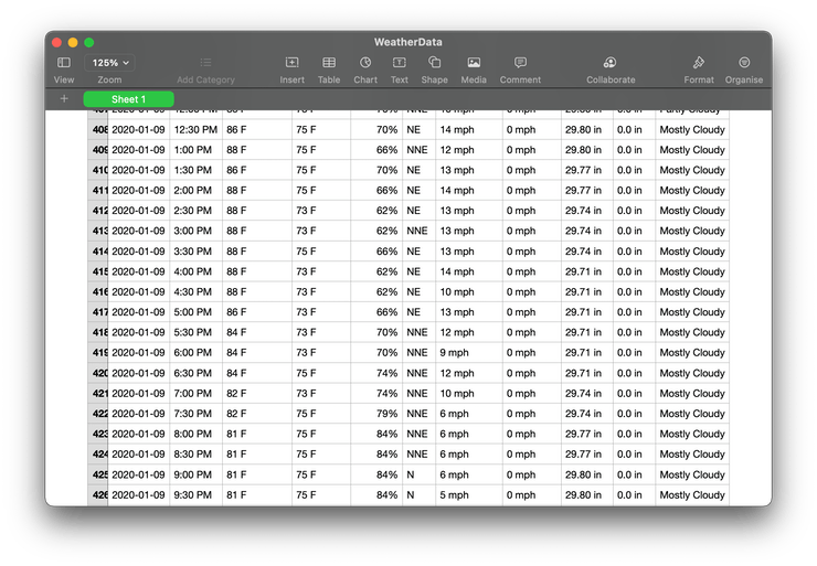
Finally, you should have the collected data in CSV format. Your CSV file should look similar to the below image.

Scraped-Weather-Data

Training the TensorFlow Lite Model with Weather Data

The collected weather data needs to be trained to build the model for the prediction task. You can use Python notebooks which allow you to run a particular part of code, this reduces complexity and helps you monitor the status of the project. You should take care of the order of execution programs to avoid any errors.

Install the depending python libraries for training the ML model. The TensorFlow and Scikit-learn libraries are required for the training of the model. TensorFlow is used for building the model, whereas Scikit-learn is for useful data processing operations.

Python Snippets

pip install tensorflow scikit-learn

The intelligent weather station will work on the real-time temperature and humidity data for predicting the weather conditions. Hence, you need to remove the unnecessary columns from the dataset. Also, you need to typecast the string values into integer values and the conversion of temperature data in Kelvin(K) form.

Python Code Snippet

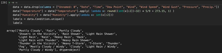
The following step is significant in terms of data structuring. As In the former sections of the code, unique labels were shown for the weather conditions. As there were so many options available for outputs for our model. It takes two inputs in which you will have to convert the labels into three categories.

Hence you will see three lists that divide these labels into “No Rain,” “Might Rain,” and “Rain” groups. The values are then one-hot coded to display the groups numerically. You also have an option to adjust these labels to be more effective for the climate of your locality.

norain = ['Mostly Cloudy', 'Fair', ... , 'Partly Cloudy / Windy']
mightrain = ['Showers in the Vicinity', 'Thunder in the Vicinity', 'Thunder']
rain = ['Rain Shower', 'Light Rain Shower', 'Light Rain', ... , 'Light Rain / Windy']

For using the input data efficiently, you have to perform prediction for a seven-input window at an instance. Each data point from the website depicts the “reading taken at half an hour interval.” Hence, the half-hourly predictions can be made with the “current + 6 previous half-hourly readings.”

It enables to support more features for the model to establish the relation between input-output data points. This can improve the accuracy and efficiency of the classification performance. Ensure the length of the arrays is the same after completing this step.

You have to split the data for training and testing using the scikit-learn library, using its train_test_split() method.

xtrain, xtest, ytrain, ytest = train_test_split(x, y, test_size = 0.20, random_state = 33)

The environment is now ready to define the model using the TensorFlow library. Once you determine the mode, then compile and fit it to the train data, which was split from the main data in the previous step. Finally, you have the model.h file, which is to be integrated into the Wio Terminal. Do this by replacing the model.h file in the WioTerminal_SmartWeatherStation folder where the Arduino code is present.

model = tf.keras.Sequential()
model.add(Dense(14, activation='relu'))
model.add(Dense(8, activation='relu'))
model.add(Dense(3, activation='softmax'))
 
model.compile(loss = 'categorical_crossentropy',
              optimizer = tf.optimizers.Adam(),
              metrics=['accuracy'])
 
model.fit(xtrain, ytrain, epochs=10, validation_split=0.1)

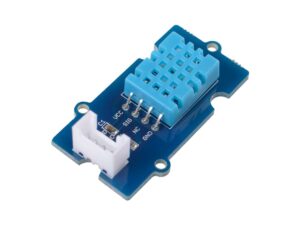
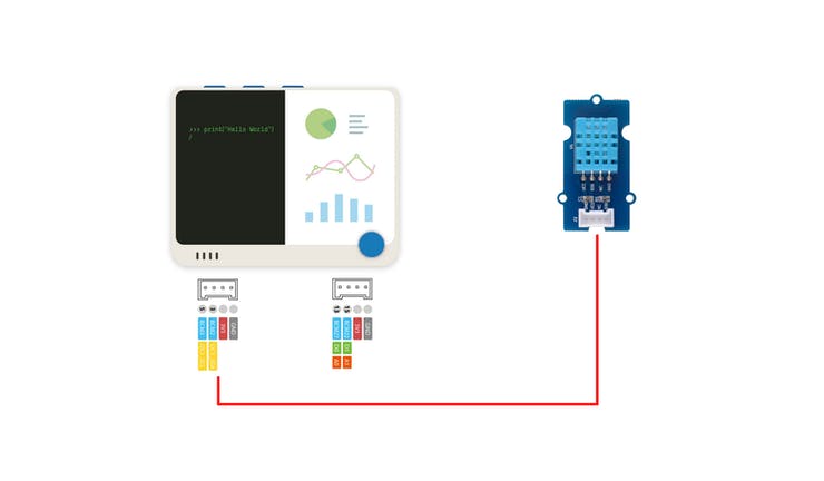
Connecting Sensor into Wio Terminal

Connect the DHT11 temperature and humidity sensor into the Wio Terminal as shown in the below image.

Connecting-Sensor-to-Wio-Terminal

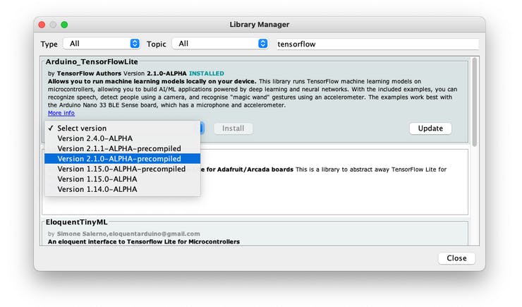
Installing the Libraries for Wio Terminal

If you are working on Wio Terminal for the first time, then refer to this getting started documentation. Now, download and install the Seeed DHT Library. If you are installing Arduino libraries through ZIP files for the first time then follow this documentation. After completing the above process, install the Arduino TensorFlowLite library via Manage Libraries in the tools section.

Wio-Library-Manager

Slight Alteration to Arduino Code

Most of you may have tried to customize the model and dataset with respect to your choice. If you changed the labels according to your use case in model outputs, then edit the parameters of the code accordingly.

const char* OUTPUTS[] = {
    "No Rain",
    "Might Rain",
    "Rain"
};
int NUM_OUTPUTS = 3;

When making edits to the Arduino sketch, it’s important to ensure that the amount of memory should not exceed 192 kilobytes. Else the Wio Terminal may hang numerous times when it called the AllocateTensors() function, this may be due to less availability of the memory.

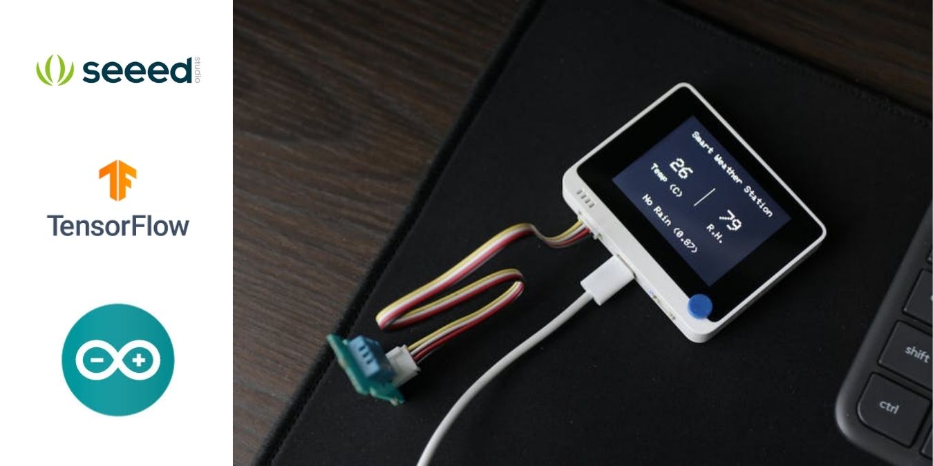
Deployed Smart Weather Station

Deployed-Smart-Weather-Station

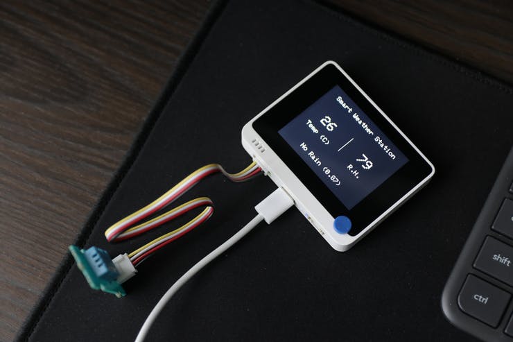
The TinyML smart weather station is finally working with the deployed TensorFlow Lite model. The image below shows the 7 half-hourly readings. The update occurs as soon as the new data comes in. For detailed information on the project, visit the Hackster’s post by Jonathan Tan.

Via Hackster

Automatic LED Stairway Lighting – Arduino Compatible

This creative idea is suitable for a stairway with 16 stairs, each stair can have a 12V LED. It has two sensors one at the start and one at the end of the stairs and when the sensor trigered at any end it starts a process of lighting each of the steps in a progressive cycle starts. When you reach the other side of the stairway and the second sensor is triggered it will start to extinguish all the lit lights in the ascending cycle.

This is a very simple and easy to build project based on the Arduino platform The board consists of an ATMEGA328 microcontroller, 16 channel MOSFETs, 2 optical retro-reflective or optical defuse sensor, 16 x 12V LEDs, LM7805 regulator, DC filter capacitors, and optional current limiting resistor on each MOSFET. The circuit requires 12V DC, each MOSFET can drive a LED up to 1A (0.5 to 12W LED)

LEDs: Each MOSFET can drive LED of 0.5W to 12W, it is advisable to use 12V LEDs, use appropriate current limiting resistors (R3, R15, R23, R31, R7, R17, R25, R33, R11, R19, R27, R35, R13, R21, R29, R37) if lower voltage LEDs is used. The default value for these resistors is 0 Ohms.

Sensor: Optical Retro-reflective sensor or optical defuse sensor can be used. The project is tested with a reflective sensor from Omron, NPN type sensor is best suitable. The optical sensor has a supply range of 12V to 24V DC which is within the supply range to interface with this project. Retroreflective sensor E3F3-R11 from Omron is suitable, it has 3 meters range with an open collector NPN type. Defuse sensor E3F3-D12 can also be used if it used in a narrow range.

Stairway: Circuit can drive 16 channels, for more steps, use multiple LEDs in parallel configuration considering load should not exceed 1A on each channel.

Cooling: It is advisable to use forced air to cool down the MOSFETs if full load 1A on each channel is used, load up to 0.5A on each channel doesn’t require a fan.

Arduino Code

Arduino example code is provided as a download. This code can be modified as per user requirements, delay between LED ON/OFF can be changed in code.  Follow the link below to learn programming the new ATMEGA328 microcontroller using Arduino IDE.

https://www.arduino.cc/en/Tutorial/BuiltInExamples/ArduinoToBreadboard

Features

  • Operating Supply 12V DC
  • 16 Channels x 12V LEDs
  • Load up to 1A x 16 Channel
  • PCB Dimensions 154.31  x 55.40mm

Schematic

Parts List

SRQNTY.REF.DESC.MANUFACTURERSUPPLIERSUPPLIER PART NO
11CN12 PIN SCREW TERMINAL 5.08MM PITCHPHOENIXDIGIKEY277-1247-ND
29CN2 to CN112 PIN SCREW TERMINAL 5.08MM PITCHPHOENIXDIGIKEY277-1247-ND
2R2,R5,CN7,C7,R9DNPDIGIKEYOMIT
38R10,R40,R42DNPDIGIKEYOMIT
42CN12,CN133 PIN MALE HEADER 2.54MM PITCHWURTHDIGIKEY732-5316-ND
52C1,C8470uF/25 ELECTROLYTICRUBYCONDIGIKEY1189-1869-ND
63C2,C60.1uF/50V SMD SIZE 0805MURATA/YAGEODIGIKEY
71C310uF/10V SMD SIZE 1206MURATA/YAGEODIGIKEY
82C4,C522PF/50V SMD SIZE 0805MURATA/YAGEODIGIKEY
916Q1 to Q16IRLR7843INFINIONDIGIKEY448-IRLR7843TRLPBFCT-ND
101R110K 5% SMD SIZE 0805MURATA/YAGEODIGIKEY
10R3,R7,R11,R13,R150E SMD SIZE 2512BOURNSDIGIKEYCR2512-J/-000ELFCT-ND
10R17,R19,R21,R23,R250E SMD SIZE 2512BOURNSDIGIKEYCR2512-J/-000ELFCT-ND
1115R27,R29,R33,R35,R370E SMD SIZE 2512BOURNSDIGIKEYCR2512-J/-000ELFCT-ND
11R4,R8,R12,R14,R16,R1810E 5% SMD SIZE 0805MURATA/YAGEODIGIKEY
11R20,R22,R24,R26,R28,R3010E 5% SMD SIZE 0805MURATA/YAGEODIGIKEY
1219R31,R32,R34,R36,R38,R39,R4110E 5% SMD SIZE 0805MURATA/YAGEODIGIKEY
131R61M 5% SMD SIZE 0805MURATA/YAGEODIGIKEY
141U1ATMEGA328 DIPMICROCHIPDIGIKEYATMEGA328P-PU-ND
151U2LM7805ONSEMIDIGIKEYMC78M05CDTGOS-ND
161Y116MHZECS INC.DIGIKEYX1103-ND
171C91uF/25VTDKDIGIKEY445-5914-1-ND

Connections

Sensor

Installation

Sensor Placement

Gerber View

Code

/*
Modified code, Original Author, Monkfish's LED stair lights
*/
 
  //LED pin assignments
  int led1 = 0;
  int led2 = 1;
  int led3 = 2;
  int led4 = 3;
  int led5 = 4;
  int led6 = 5;
  int led7 = 6;
  int led8 = 7;
  int led9 = 8;
  int led10 = 9;
  int led11 = 10;
  int led12 = 11;
  int led13 = 12;
  int led14 = 13;
  int led15 = A0;
  int led16 = A1;
    
  // button pin assignments
  int b_up = A4; //button at bottom of stairs
  int b_down = A5; //button at top of stairs
 
  //LED delay settings
  int tOn = 400; //LED On delay
  int tOff = 750; //LED Off delay
  int del = 0; //Delay after action (used for debugging - set to 500-1000 to introduce a delay between each action)
  
  //variables
  static unsigned activeup = 0; //whether the system is active going upwards
  static unsigned activedown = 0; //whether the system is active going downwards
  
void setup() { //make with the setups
   
  //Set LED pins as output
  pinMode(led1, OUTPUT);
  pinMode(led2, OUTPUT);
  pinMode(led3, OUTPUT);
  pinMode(led4, OUTPUT);
  pinMode(led5, OUTPUT);
  pinMode(led6, OUTPUT);
  pinMode(led7, OUTPUT);
  pinMode(led8, OUTPUT);
  pinMode(led9, OUTPUT);
  pinMode(led10, OUTPUT);
  pinMode(led11, OUTPUT);
  pinMode(led12, OUTPUT);
  pinMode(led13, OUTPUT);
  pinMode(led14, OUTPUT);
  pinMode(led15, OUTPUT);
  pinMode(led16, OUTPUT);
  
  //Set button pins as input
  pinMode(b_up, INPUT_PULLUP);
  pinMode(b_down, INPUT_PULLUP);
 
  //Clear variables
  int activedown = 0;
  int activeup = 0;
}
 
void loop() {  //forever in your loopings
      
      //Set variables based on pin state
      int up = digitalRead(b_up);
      int down = digitalRead(b_down);
    
  if (up == LOW){ //Bottom button pressed
    
      
      //Set variables
      
          if (activeup == 1 || activedown == 1){ //checks if system active
                
                //If active
                
                OffDown(); //function call
                        
          } else { 
            
            //if not active            
          
            delay(del);
      
            OnUp(); //function call
            
          }
      
      
  }
     
  if (down == LOW){
         
      if (activeup == 1 || activedown == 1){

                
                OffUp(); //function call
                        
          } else  {


            OnDown(); //function call
            
          }
       
  }
 
        
}
 
void OnUp(){ //Switches lights on going up


               //set LEDs on in turn
               digitalWrite(led1, HIGH);
               delay(tOn);
               digitalWrite(led2, HIGH);
               delay(tOn);
               digitalWrite(led3, HIGH);
               delay(tOn);
               digitalWrite(led4, HIGH);
               delay(tOn);
               digitalWrite(led5, HIGH);
               delay(tOn);
               digitalWrite(led6, HIGH);
               delay(tOn);
               digitalWrite(led7, HIGH);
               delay(tOn);
               digitalWrite(led8, HIGH);
               delay(tOn);
               digitalWrite(led9, HIGH);
               delay(tOn);
               digitalWrite(led10, HIGH);
               delay(tOn);
               digitalWrite(led11, HIGH);
               delay(tOn);
               digitalWrite(led12, HIGH);
               delay(tOn);
               digitalWrite(led13, HIGH);
               delay(tOn);
               digitalWrite(led14, HIGH);
               delay(tOn);
               digitalWrite(led15, HIGH);
               delay(tOn);
               digitalWrite(led16, HIGH);
               
               activeup = 1; //Set system as active up

                               
} //end OnUp
 
void OffUp(){ //switches lights off going up


         //sets LEDs off in turn
         digitalWrite(led1, LOW);
         delay(tOff);
         digitalWrite(led2, LOW);
         delay(tOff);
         digitalWrite(led3, LOW);
         delay(tOff);
         digitalWrite(led4, LOW);
         delay(tOff);
         digitalWrite(led5, LOW);
         delay(tOff);
         digitalWrite(led6, LOW);
         delay(tOff);
         digitalWrite(led7, LOW);
         delay(tOff);
         digitalWrite(led8, LOW);
         delay(tOff);
         digitalWrite(led9, LOW);
         delay(tOff);
         digitalWrite(led10, LOW);
         delay(tOff);
         digitalWrite(led11, LOW);
         delay(tOff);
         digitalWrite(led12, LOW);
         delay(tOff);
         digitalWrite(led13, LOW);
         delay(tOff);
         digitalWrite(led14, LOW);
         delay(tOff);
         digitalWrite(led15, LOW);
         delay(tOff);
         digitalWrite(led16, LOW);
         
         //set system as being off
         activeup = 0;
         activedown = 0;

         
} //End OffUp
 
void OnDown(){ //switches lights on going down

               
         //set LEDs on in turn
         digitalWrite(led16, HIGH);
         delay(tOn);
         digitalWrite(led15, HIGH);
         delay(tOn);
         digitalWrite(led14, HIGH);
         delay(tOn);
         digitalWrite(led13, HIGH);
         delay(tOn);
         digitalWrite(led12, HIGH);
         delay(tOn);
         digitalWrite(led11, HIGH);
         delay(tOn);
         digitalWrite(led10, HIGH);
         delay(tOn);
         digitalWrite(led9, HIGH);
         delay(tOn);
         digitalWrite(led8, HIGH);
         delay(tOn);
         digitalWrite(led7, HIGH);
         delay(tOn);
         digitalWrite(led6, HIGH);
         delay(tOn);
         digitalWrite(led5, HIGH);
         delay(tOn);
         digitalWrite(led4, HIGH);
         delay(tOn);
         digitalWrite(led3, HIGH);
         delay(tOn);
         digitalWrite(led2, HIGH);
         delay(tOn);
         digitalWrite(led1, HIGH);
         
         activedown = 1; //sets system as active down

  
} //End OnDown
 
void OffDown(){ //switches lights off going down

       //sets LEDs off in turn
       digitalWrite(led16, LOW);
       delay(tOff);
       digitalWrite(led15, LOW);
       delay(tOff);
       digitalWrite(led14, LOW);
       delay(tOff);
       digitalWrite(led13, LOW);
       delay(tOff);
       digitalWrite(led12, LOW);
       delay(tOff);
       digitalWrite(led11, LOW);
       delay(tOff);
       digitalWrite(led10, LOW);
       delay(tOff);
       digitalWrite(led9, LOW);
       delay(tOff);
       digitalWrite(led8, LOW);
       delay(tOff);
       digitalWrite(led7, LOW);
       delay(tOff);
       digitalWrite(led6, LOW);
       delay(tOff);
       digitalWrite(led5, LOW);
       delay(tOff);
       digitalWrite(led4, LOW);
       delay(tOff);
       digitalWrite(led3, LOW);
       delay(tOff);
       digitalWrite(led2, LOW);
       delay(tOff);
       digitalWrite(led1, LOW);
       
       //set system as not active
       activedown = 0;
       activeup = 0;


}//End OffDown


Photos

Video

IRLR7843 Datasheet

TOP PCB Companies